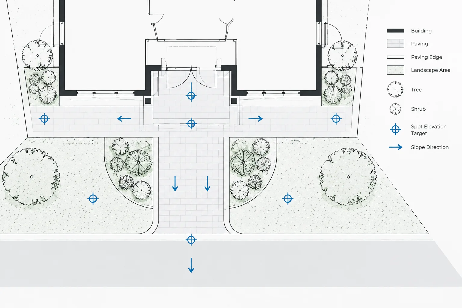
Spot elevations and slope arrows connect architectural site graphics with the vertical relationships that govern entrances, paving, walls, landscape transitions, and drainage intent. Their usefulness depends on more than legible symbols: every annotation must remain tied to a defined point, a known reference, and a current source.
This guide explains how to organize these annotations in CAD, distinguish their status, coordinate them with related drawings, and review them without treating consultant information as ordinary drafting text.
Spot elevations and slope arrows help translate site grading information into points and directions that can be read directly from an architectural plan. They may identify pavement elevations, building entry levels, wall tops, drainage points, landscape transitions, and other locations where vertical coordination matters.
These annotations appear simple, but they can become unreliable when their datum, status, target point, or source is unclear. A spot elevation copied from an outdated background may look authoritative even when it no longer matches the current grading design. A slope arrow can also be misread if the drawing does not establish whether it points uphill, downhill, or toward drainage.
A dependable CAD workflow treats spot elevations as coordinated design data rather than ordinary text. The goal is to make each annotation traceable, readable, and easy to review against the site plan, building plans, and consultant backgrounds.
What a Spot Elevation Represents
A spot elevation identifies the vertical level of a specific point. The displayed value is meaningful only when the drawing team understands the associated datum, units, precision, and physical location.
The target may be a pavement corner, threshold, curb point, landing, drain, wall, slab, grade break, or another defined feature. A symbol placed near an object is not enough; readers must be able to determine exactly where the elevation applies.
Architectural drawings may show spot elevations for coordination, but the source often comes from survey, civil, landscape, structural, or architectural design information. Do not infer a construction elevation from nearby graphics unless calculating and documenting that elevation is part of the assigned design scope.
Establish the Vertical Reference Before Drafting
Before adding elevation labels, confirm the vertical reference used by the project. Some backgrounds may use survey elevations, while architectural drawings may use a project-relative reference. Mixing these systems without a documented relationship can create apparently plausible but incorrect annotations.
Confirm the following with the project team:
- The datum or benchmark associated with the elevations.
- The drawing units and expected display precision.
- Whether values represent existing, proposed, or verified field conditions.
- Whether the architectural file should retain the source values or display a coordinated project-relative value.
- Who is responsible for approving changes to grading information.
Place a clear datum note or reference where appropriate in the drawing set. If more than one vertical reference must be shown, label each system explicitly rather than relying on graphic differences alone.
Create a Consistent Spot Elevation Symbol
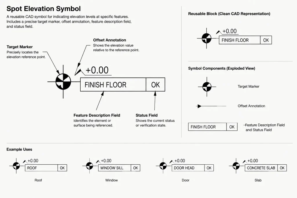
A reusable block is usually more dependable than separately drawn lines and text. The block can combine a target marker with attributes for the elevation, point description, and status. Keep the insertion point at the exact location being measured so that moving the symbol does not separate the label from its intended target.
A practical spot elevation block may contain:
| Component | Purpose |
|---|---|
| Target marker | Identifies the precise plan location to which the elevation applies. |
| Elevation value | Displays the coordinated vertical level using the project’s agreed format. |
| Feature description | Clarifies whether the point refers to paving, grade, a threshold, a wall, or another element. |
| Status identifier | Distinguishes existing, proposed, surveyed, or other project-defined conditions. |
| Source or check field | Supports internal tracking when the team needs to record where the value originated. |
Not every field needs to appear on the plotted sheet. Internal information can remain in attributes or project tracking data while the visible symbol stays concise. Avoid placing critical meaning only in color because plotted output and grayscale review may remove that distinction.
Organize Elevation Annotations by Layer and Status
Separate spot elevations from general notes so they can be reviewed and displayed independently. Depending on the project structure, existing and proposed values may also need separate layers. Slope arrows, drainage direction graphics, and temporary checking geometry can have their own controlled layers.
A useful organization distinguishes among:
- Existing elevation symbols received from a verified background.
- Proposed elevations controlled by the current design.
- Slope arrows and grade-direction indicators.
- Reference or calculation graphics that should not plot.
- Superseded information retained temporarily for comparison.
Use object properties consistently. Unexplained color, linetype, or lineweight overrides make it harder to determine whether a graphic difference has design meaning or is simply a drafting inconsistency.
Place Spot Elevations at Meaningful Control Points
More spot elevations do not automatically create a better plan. Place them where the surface changes, where construction needs a defined control, or where another drawing system must connect to the site.
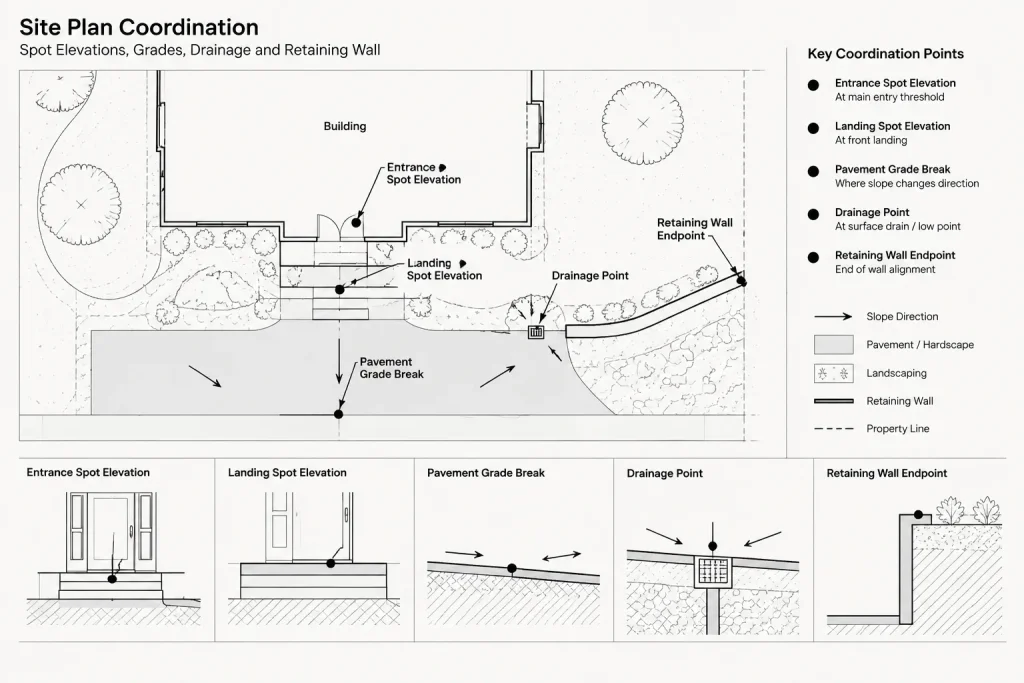
Common coordination locations include building entrances, landing edges, pavement intersections, grade breaks, drainage structures, wall endpoints, ramp transitions, and interfaces between landscape and hardscape. The exact set depends on the project and the responsible discipline.
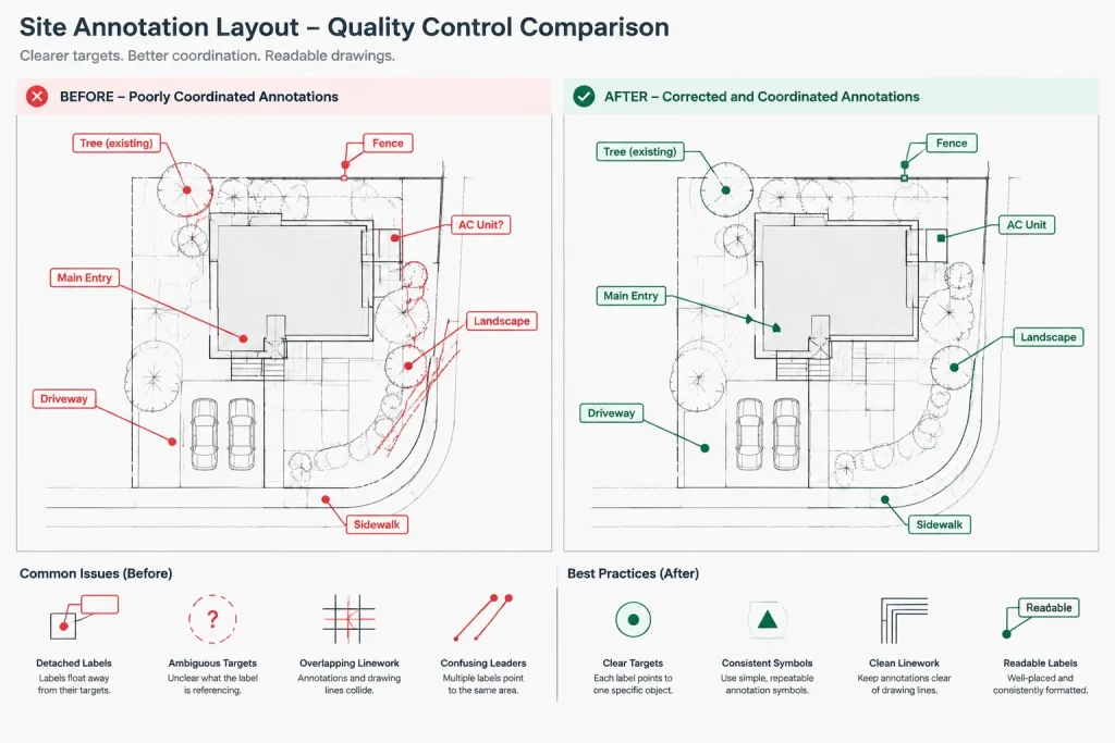
Keep the target marker on the actual point. The text may be offset for readability, but use a leader or a block configuration that preserves the connection. Avoid allowing a label to float between several corners where its intended location becomes ambiguous.
Draft Slope Arrows Without Creating Ambiguity
A slope arrow communicates direction across a surface. Its meaning must be consistent throughout the project. Some teams point arrows toward lower elevations or drainage, while other drawing conventions may use a different directional meaning. State or demonstrate the convention in the relevant legend instead of assuming every reader will interpret it the same way.
Place the arrow along the actual direction being described. Avoid using a diagonal arrow merely to fit available space if the surface slopes in another direction. If the slope changes across a warped or multi-plane surface, separate arrows or additional control points may be necessary.
When a slope value is calculated from two spot elevations, the relationship is based on the vertical difference divided by the applicable horizontal run. Confirm that both elevations use the same datum and that the plan distance represents the intended path. Rounded labels should not be used to conceal a mismatch between the controlling elevations and the stated slope.
A Practical CAD Coordination Workflow
Review the source background
Identify which file contains the current survey or grading information. Check its origin, rotation, units, clipping, and revision status before relying on any displayed value. If a consultant background is replaced, compare it with the previous version rather than assuming only graphics changed.
Define annotation rules
Agree on the spot elevation symbol, layer assignments, precision, status labels, and slope-arrow convention. Add these settings to the project template or documented CAD procedures where practical.
Place verified control points first
Begin with points that connect major systems, such as building entries and established site controls. Then add intermediate points needed to explain transitions and drainage behavior.
Coordinate adjacent drawings
Compare site elevations with floor plans, enlarged entrance plans, ramp and stair drawings, foundation information, exterior elevations, and relevant details. A doorway shown level in one view and stepped in another is a coordination issue even if each drawing appears graphically complete.
Review the plotted sheet
Inspect the final sheet at its intended output scale. Confirm that target markers remain visible, decimal characters are readable, leaders do not merge with paving lines, and existing and proposed conditions remain distinguishable in monochrome output.
Common Errors to Check
- Detached text: The elevation value has moved away from its target point.
- Mixed datums: Values from different vertical references appear together without conversion or labeling.
- Unclear status: Existing and proposed elevations use identical graphics with no reliable identifier.
- Outdated background data: Architectural annotations still reflect an earlier civil or survey file.
- Contradictory slope information: The arrow direction, stated slope, and endpoint elevations do not agree.
- False precision: The displayed number implies more certainty than the source information supports.
- Obscured targets: Hatches, paving joints, or other linework hide the exact point being labeled.
- Uncoordinated entrances: Site grades do not align with the current architectural threshold or landing design.
Final Quality-Control Checklist
- Confirm the datum, units, and precision used by every displayed elevation.
- Verify that each symbol targets a clearly identifiable point.
- Check existing and proposed annotations for an unmistakable graphic distinction.
- Compare critical values with the current source background.
- Review slope arrows against endpoint elevations and drainage intent.
- Coordinate entrances, ramps, stairs, walls, paving, and landscape transitions.
- Remove or isolate temporary calculation geometry before issue.
- Inspect the plotted PDF rather than relying only on model-space appearance.
Well-coordinated spot elevations turn a site plan into a clearer vertical control document. Consistent symbols, explicit status information, verified source data, and disciplined review help prevent elevation notes from becoming disconnected numbers. The architectural drawing should communicate the intended relationship between the building and site while clearly identifying which information requires confirmation by the responsible project discipline.
Read Elevation Annotations as Coordinated Information
A reviewer should be able to trace each spot elevation through a simple chain: source, status, target point, and displayed value. If any part of that chain is uncertain, the annotation should be treated as unresolved rather than assumed to be correct.
The same principle applies to slope arrows. An arrow communicates direction only when the drawing also establishes what that direction means. It does not independently confirm the surface geometry, drainage performance, or agreement between endpoint elevations.
Manage Revisions Without Losing Provenance
When a survey, civil plan, landscape plan, or other background changes, review the affected annotations as coordinated data. Do not rely solely on whether the surrounding linework appears different. Elevation values, point locations, status descriptions, and grading intent may change independently.
Keep received information distinguishable from architectural annotations created for coordination. If a value must be transferred into an architectural file, retain enough source and status information for another team member to determine where it originated. Superseded annotations should be removed from issued views or clearly isolated while comparisons are underway.
Separate Graphic Clarity From Technical Approval
A clean symbol and a well-positioned arrow improve communication, but they do not establish that the underlying grading information has been approved. CAD quality control should therefore address both appearance and authority. Check that the annotation is readable, then confirm that it comes from the responsible source and remains consistent with the current design.
Where information is unresolved, use the project’s established review process rather than filling gaps by interpolation or assumption. This is especially important at building entrances and other interfaces where architectural and site information meet.
Frequently Asked Questions
What is the difference between a spot elevation and a slope arrow?
A spot elevation identifies the vertical level at a defined point. A slope arrow communicates direction across a surface. The arrow may be coordinated with spot elevations, but it does not replace the need for clear control points.
Where should the insertion point of a spot elevation block be placed?
Place it at the exact plan location represented by the elevation. The visible text can be offset for clarity, but the target marker and annotation must remain unambiguously connected.
Should slope arrows point uphill or downhill?
Either convention may be encountered, so the project must define and apply one meaning consistently. The legend or drawing notes should make the adopted direction clear rather than leaving it to interpretation.
Can spot elevations be copied from a consultant background?
They may be referenced or transferred when appropriate to the project workflow, but their source, datum, status, and revision must remain clear. Copying a label does not verify that it is current or suitable for architectural coordination.
How should existing and proposed elevations be distinguished?
Use the project’s established combination of layers, symbols, labels, and status fields. Do not depend on color alone because monochrome output may eliminate that distinction.
What should be checked when a slope arrow conflicts with spot elevations?
Review the arrow convention, target points, vertical reference, horizontal path, source background, and revision status. Treat the conflict as a coordination issue instead of changing one annotation merely to make the graphics appear consistent.