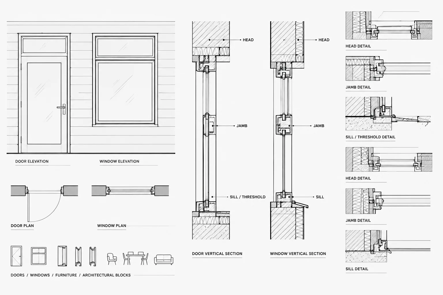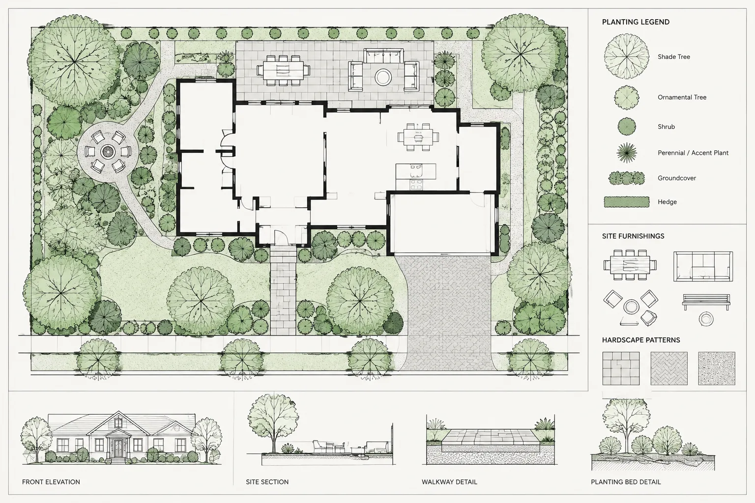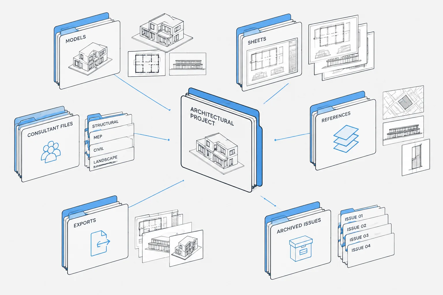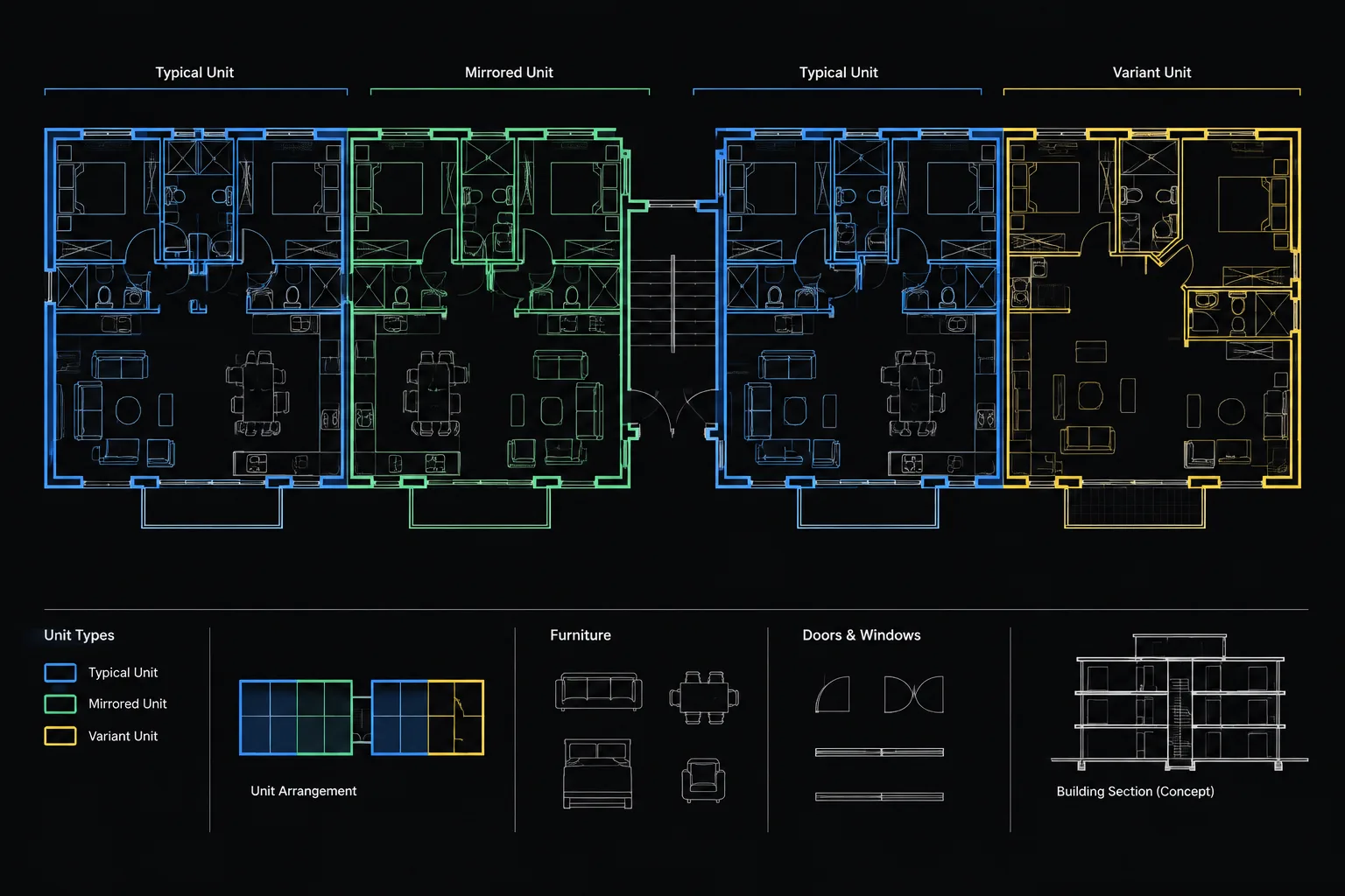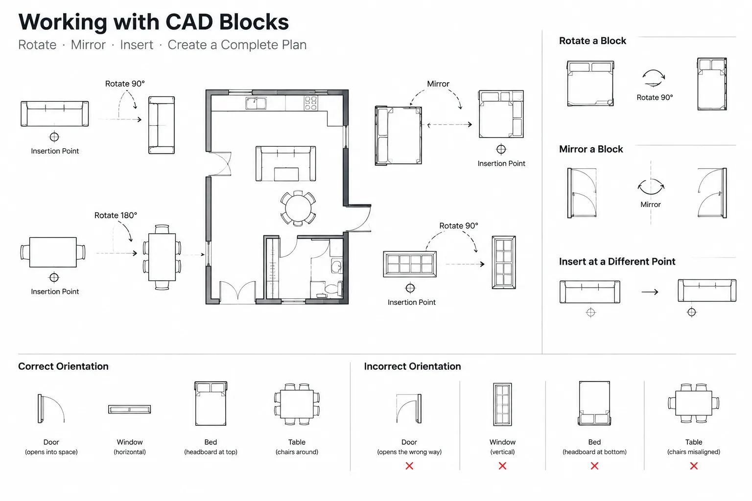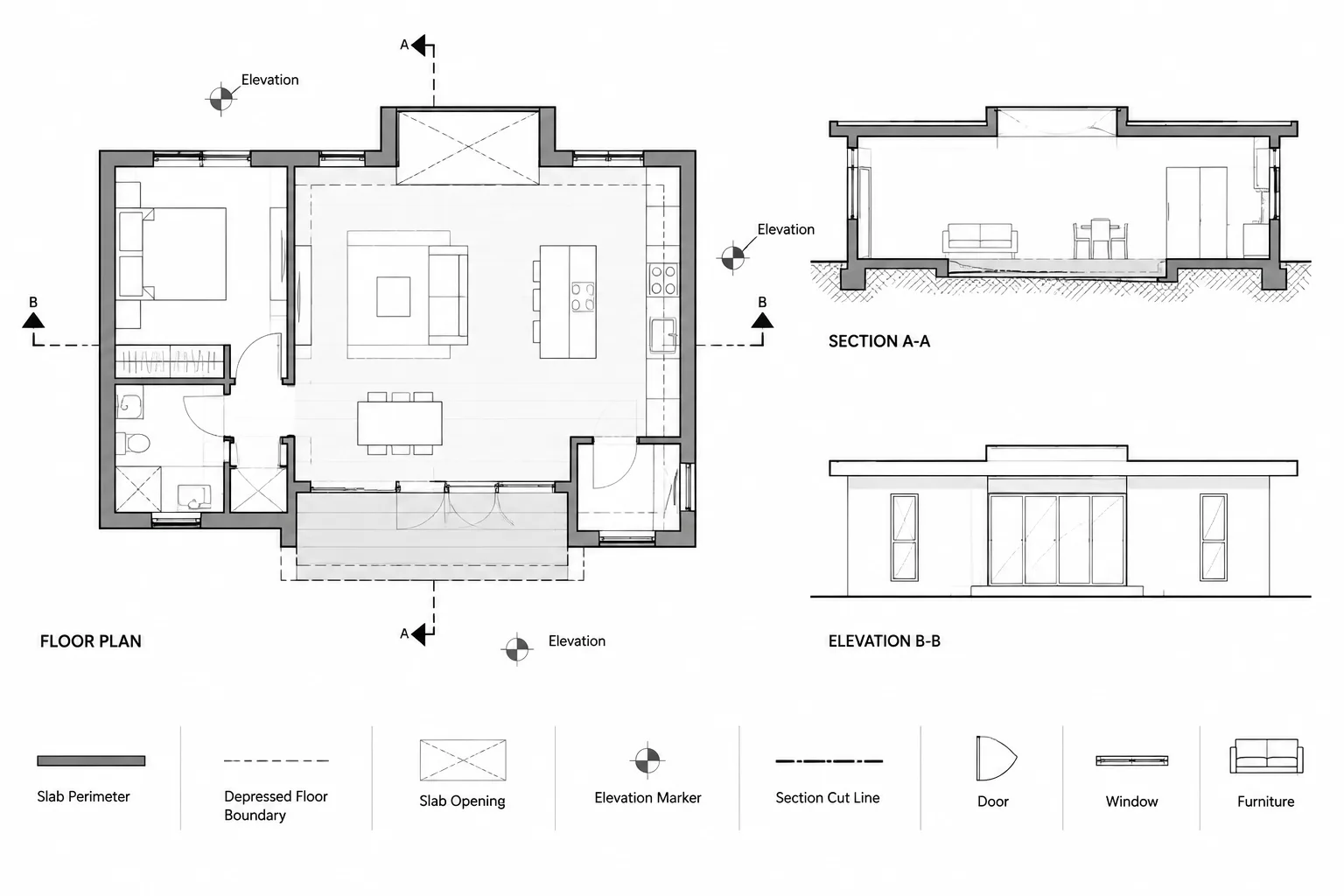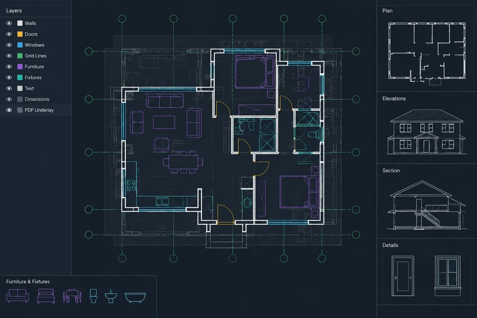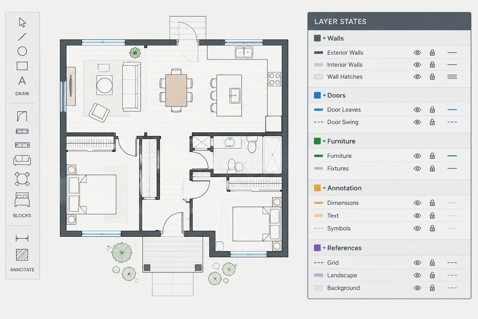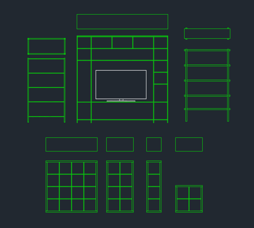
A shelving unit CAD block DWG can help communicate storage locations clearly in architectural plans, interior layouts, and presentation drawings. It provides a reusable starting point for showing how shelving relates to walls, furniture, fixtures, circulation, and other room elements.
Before adding the block to a project drawing, review the file contents, drawing units, insertion point, layers, linework, and available views. The source download and its original technical information are preserved below.
Download a detailed Shelving Unit DWG file, perfect for your architectural and interior design projects. This high-quality CAD Block offers accurate dimensions and realistic detailing, making it ideal for planning storage solutions in residential, commercial, or industrial spaces. The Shelving Unit DWG file is fully compatible with AutoCAD and other leading CAD software, ensuring seamless integration into your existing CAD drawings. Use this versatile CAD Block to enhance your layouts, improve organization, and present professional shelving design concepts to clients with ease.
Please log in or register to download this file.
How to Use the Shelving Unit CAD Block
Insert or reference the DWG in a working file, then confirm that its scale matches the project. Place the shelving in context rather than treating it as an isolated symbol. Nearby doors, windows, counters, furniture, equipment, and circulation paths can affect whether the proposed location is practical.
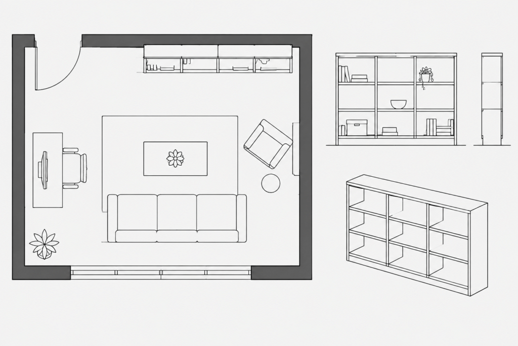
If the downloaded geometry does not match the intended shelving product, use it as a drafting reference and revise the representation only after checking the selected product or design information. A generic CAD block should not replace verified manufacturer data, project dimensions, accessibility review, structural coordination, or applicable code analysis.
Recommended CAD Workflow
- Inspect the source file: Open the DWG separately and check its geometry before bringing it into a larger project.
- Confirm drawing units: Compare a known project reference with the block so that unintended scaling is easy to identify.
- Review the insertion point: Choose a logical reference location that supports accurate placement against a wall, floor line, or layout grid.
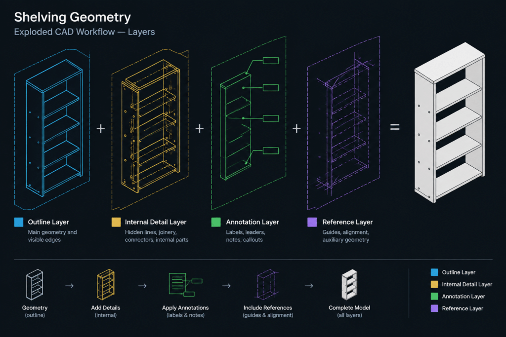
- Organize layers: Move or map the linework to the office layer system while preserving useful distinctions between outlines, internal details, and annotation.
- Clean duplicate geometry: Check for overlapping lines, stray objects, unnecessary fills, or unrelated content that could increase drawing complexity.
- Keep annotation separate: Add project-specific labels, dimensions, and notes in the host drawing rather than embedding them permanently in a reusable symbol.
- Verify plotted appearance: Review lineweights and visual hierarchy at the intended sheet presentation before issuing the drawing.
Placement and Coordination Considerations
Plan Drawings
In plan, shelving should remain legible without overpowering walls, openings, and primary furniture. Coordinate its footprint with room use, access, nearby door swings, and the placement of other fixtures. Where shelving is built in, the relationship to wall finishes and adjacent construction may also need to be shown.
Elevations and Sections
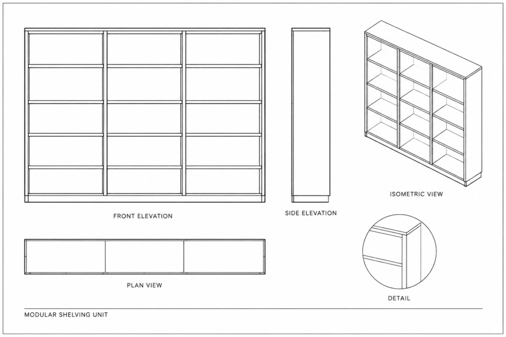
Elevation or section views can communicate vertical arrangement more effectively than a plan alone. Confirm that shelf divisions, supports, base conditions, top conditions, and surrounding construction are represented at a level appropriate to the drawing purpose. Avoid implying construction details that have not been designed or verified.
Related Drawing Resources
This block may be coordinated with furniture CAD blocks, office layouts, storage-room plans, retail fixture drawings, wall elevations, title blocks, CAD layer references, and architectural annotation resources. These related topics help connect an isolated shelving symbol to a complete and readable drawing set.
Pre-Issue Review Checklist
- The block uses the correct project units and scale.
- The shelving location agrees across plans, elevations, and sections.
- Lineweights remain clear at the intended plotting condition.
- Dimensions describe project requirements rather than unverified block geometry.
- Labels use the project naming and annotation conventions.
- Nearby doors, furniture, fixtures, and circulation have been coordinated.
- Any product-specific information has been checked against current verified documentation.
Frequently Asked Questions
What is a shelving unit CAD block?
It is reusable CAD geometry representing a shelving unit for placement in architectural, interior, storage, retail, or furniture layouts. Depending on the source file, it may include plan, elevation, section, or detail-style linework.
Should I check the DWG scale before using it?
Yes. Confirm the drawing units and compare the geometry with a verified project reference before relying on its size. Do not assume that insertion settings automatically match the host drawing.
Can the block be edited for a specific project?
DWG geometry can generally be incorporated into a project workflow and adjusted as needed, but edits should be based on verified design or product information. Preserve an untouched copy of the downloaded file for reference.
How should shelving be shown in a floor plan?
Use clear linework that communicates the unit footprint and relationship to walls, furniture, openings, and circulation. Add project-specific dimensions and labels separately so the base block remains reusable.
Is a generic shelving block sufficient for construction documents?
Not by itself. Construction documentation may require verified dimensions, materials, attachment conditions, clearances, coordination, and other project-specific information. The design professional should review the final representation for the intended use.