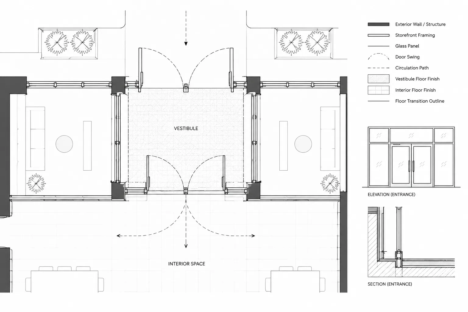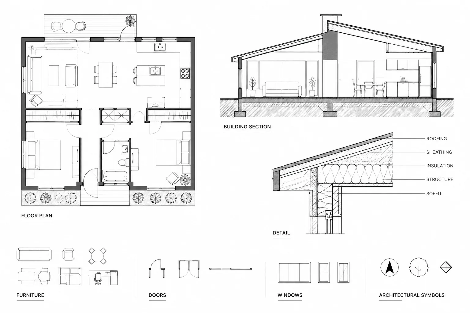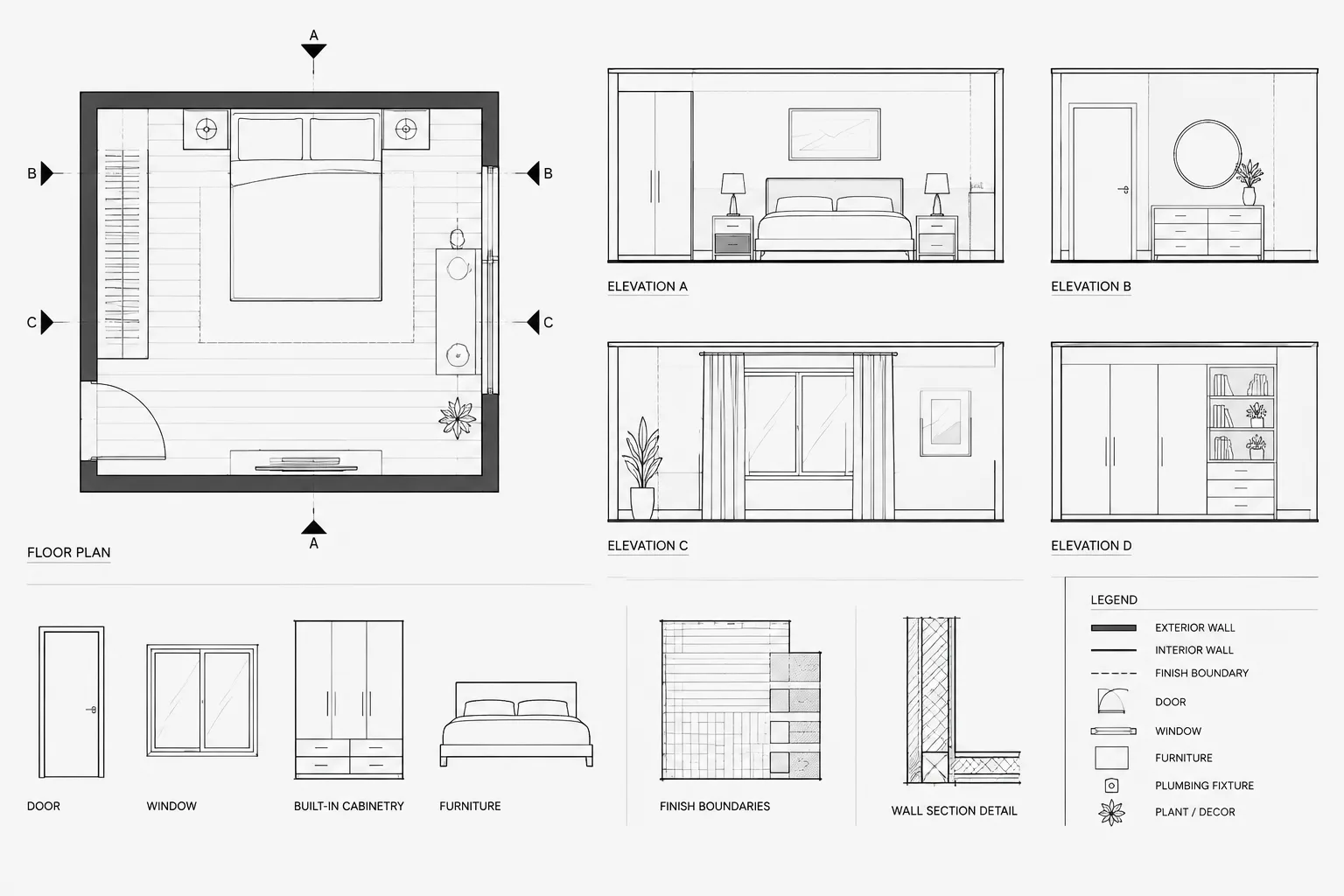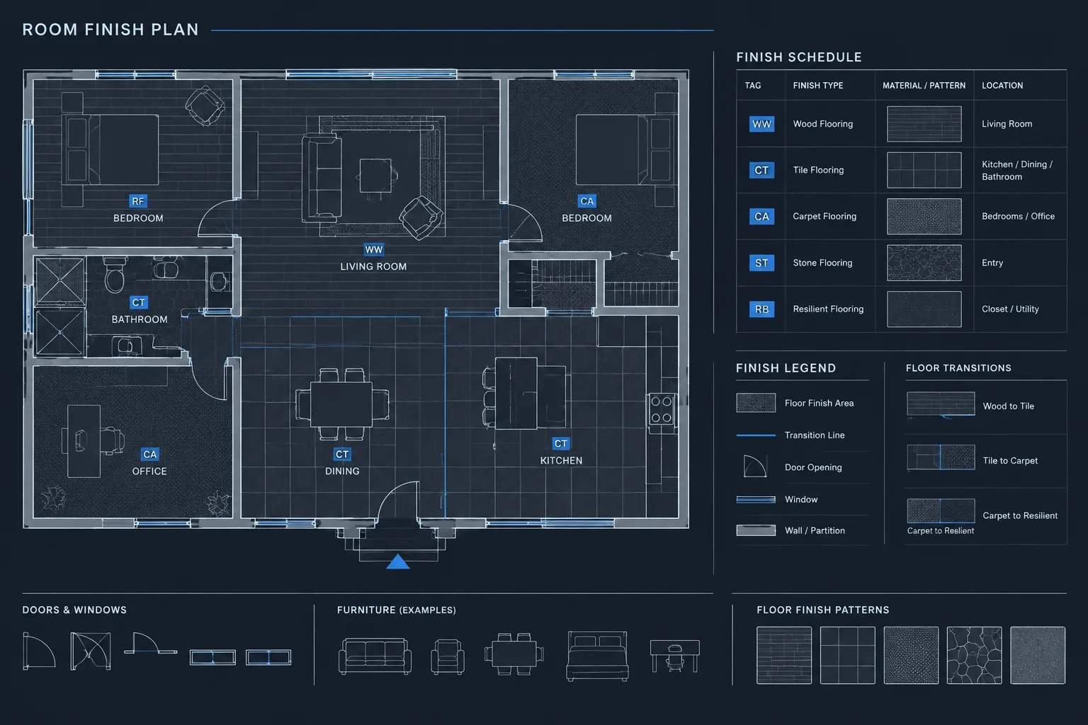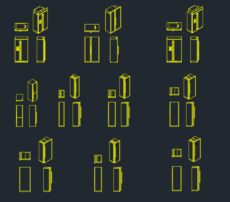
Refrigeration equipment CAD blocks provide a practical starting point for showing cooling equipment in architectural and mechanical drawing sets. They can help communicate equipment locations, coordinate room layouts, and maintain a consistent graphic style without redrawing common objects.
The downloadable DWG resource below should be treated as editable drawing content rather than a project-ready equipment specification. Before using it in a floor plan, elevation, or coordination drawing, review its units, scale, geometry, insertion point, and layer organization.
Discover a high-quality Refrigeration DWG file designed for architects, engineers, and designers working on HVAC and cooling system projects. This detailed CAD Block offers accurate representations of refrigeration units, making it easy to integrate into your building layouts and technical drawings. The Refrigeration DWG file is fully compatible with AutoCAD and other popular CAD software, ensuring smooth workflow and precise results. Perfect for commercial, industrial, and residential projects, this CAD Block enhances your design process, saving you time and improving project accuracy. Download now for seamless refrigeration system planning.
Please log in or register to download this file.
How to Use Refrigeration Equipment CAD Blocks
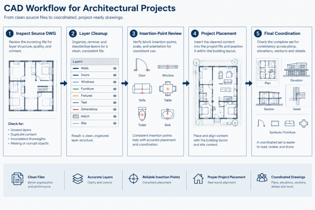
Begin by opening or attaching the DWG in a controlled working file. Inspect the block before inserting it into a project drawing so that unfamiliar layers, line types, text styles, or nested objects do not disrupt the destination file.
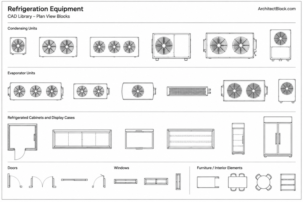
- Confirm drawing units: Compare the source geometry with a known project element before scaling or placing the block.
- Review the insertion point: A useful base point makes alignment to walls, counters, equipment rows, or service zones easier.
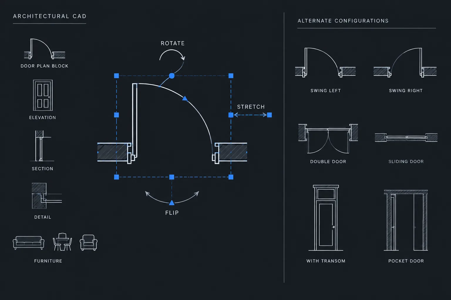
- Check the drawing view: Determine whether the geometry represents a plan, elevation, section, diagram, or another drafting view.
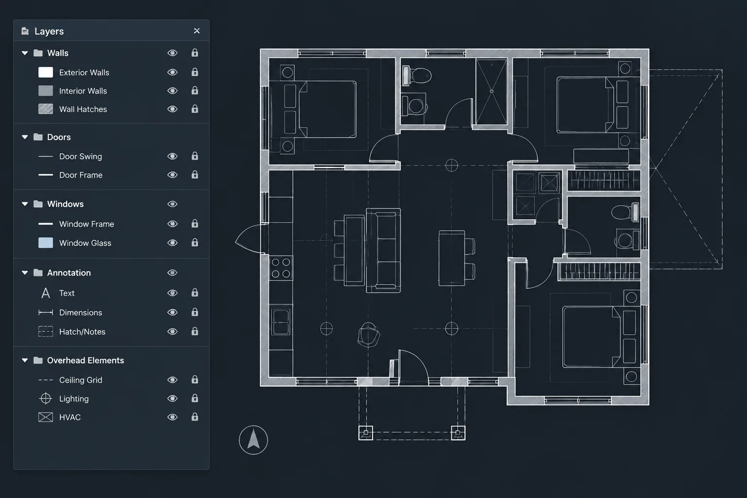
- Clean the layers: Move or map the content to the project layer standard while preserving necessary linework.
- Verify the footprint: Replace generic geometry with manufacturer-confirmed information when actual equipment has been selected.
Placement and Coordination Considerations
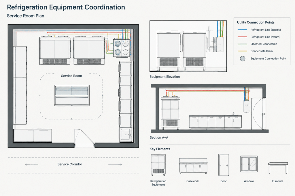
A refrigeration symbol may show where equipment is intended, but it does not establish installation requirements. Coordinate the block with adjacent walls, doors, casework, circulation paths, structural elements, and relevant building systems. Required access, ventilation, drainage, electrical service, piping, and maintenance space should be confirmed from project criteria and current manufacturer information.
For architectural plans, use a lineweight and detail level appropriate to the drawing scale. Simplified outlines are often clearer in general arrangements, while enlarged equipment or service drawings may require additional connection and access information. Avoid adding detail that cannot be verified.
Organizing the DWG in a CAD Library
After checking the file, save an approved copy within a clearly named equipment library. Group related refrigeration content with kitchen equipment blocks, mechanical symbols, fixtures, and room-layout resources. Consistent naming and layer conventions make it easier for other CAD users to identify the block and understand its intended view.
Final Drawing Checks
- Confirm that the block plots clearly at the intended sheet scale.
- Remove duplicate lines, stray objects, and unnecessary annotation.
- Check that hidden or frozen layers do not contain required geometry.
- Make sure the symbol does not imply unverified connections or clearances.
- Coordinate final equipment information with the responsible design professionals and selected product documentation.
Frequently Asked Questions
What is a refrigeration equipment CAD block?
It is reusable CAD geometry representing refrigeration equipment in a drawing view. Depending on the source file, it may function as a block definition or as editable linework that can be converted into a project-standard block.
Can this DWG be inserted directly into a floor plan?
Inspect it first. Confirm the units, scale, view orientation, layers, and insertion point before placing it in a floor plan. Generic geometry should also be checked against the equipment selected for the project.
Does the CAD block provide installation clearances?
Do not assume that visible spacing or linework represents required clearance. Installation, service, ventilation, and access requirements should come from verified project documentation and manufacturer information.
Should refrigeration blocks be placed on an architectural or mechanical layer?
Layer placement depends on the office standard and drawing purpose. Architectural plans may show the equipment footprint for layout coordination, while mechanical drawings may separate equipment, piping, services, and annotation into discipline-specific layers.
How can the block be made easier to reuse?
Use a logical base point, remove unnecessary objects, apply clear layer names, and identify the represented view. Keep an original source copy and a separate cleaned version for the project library.