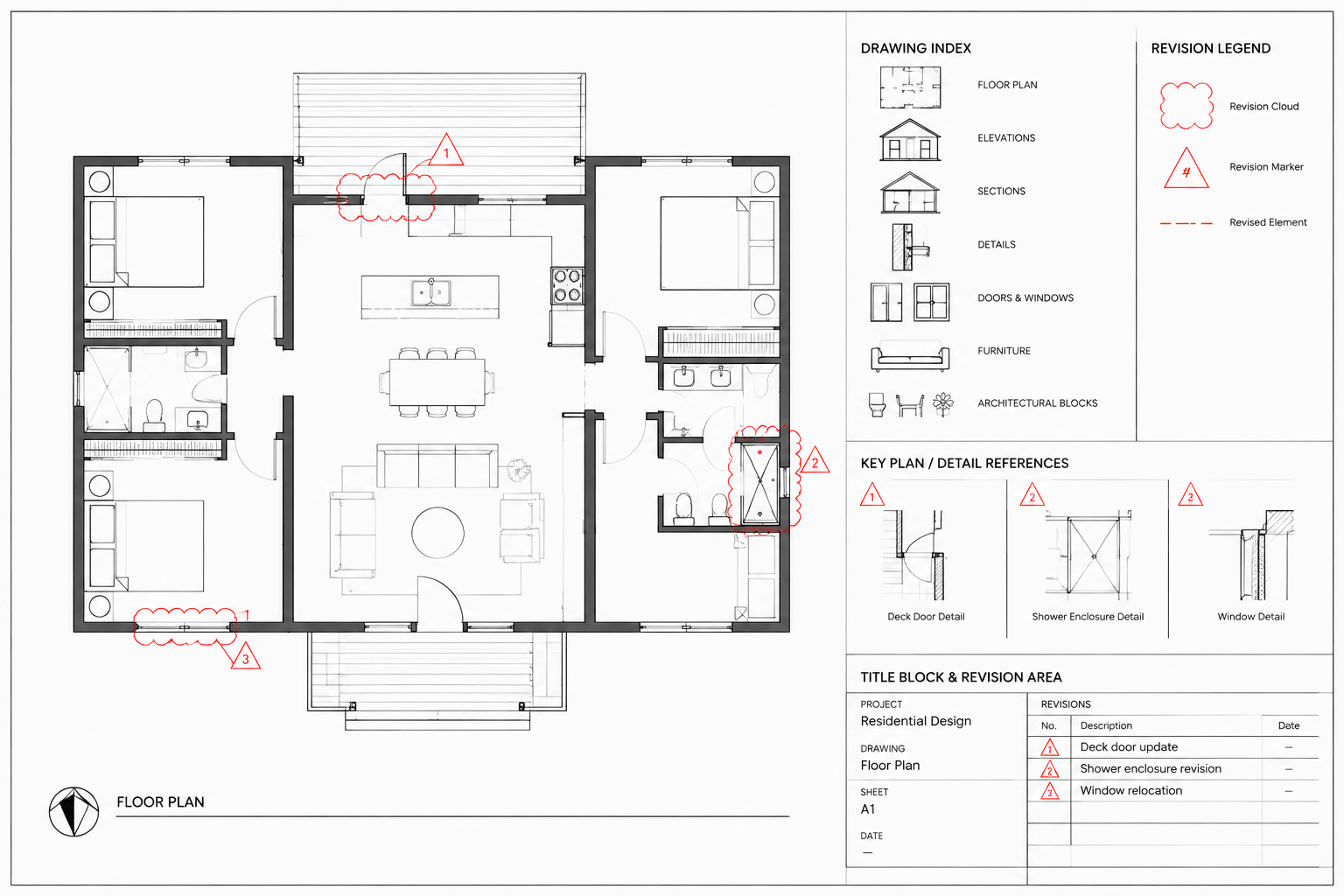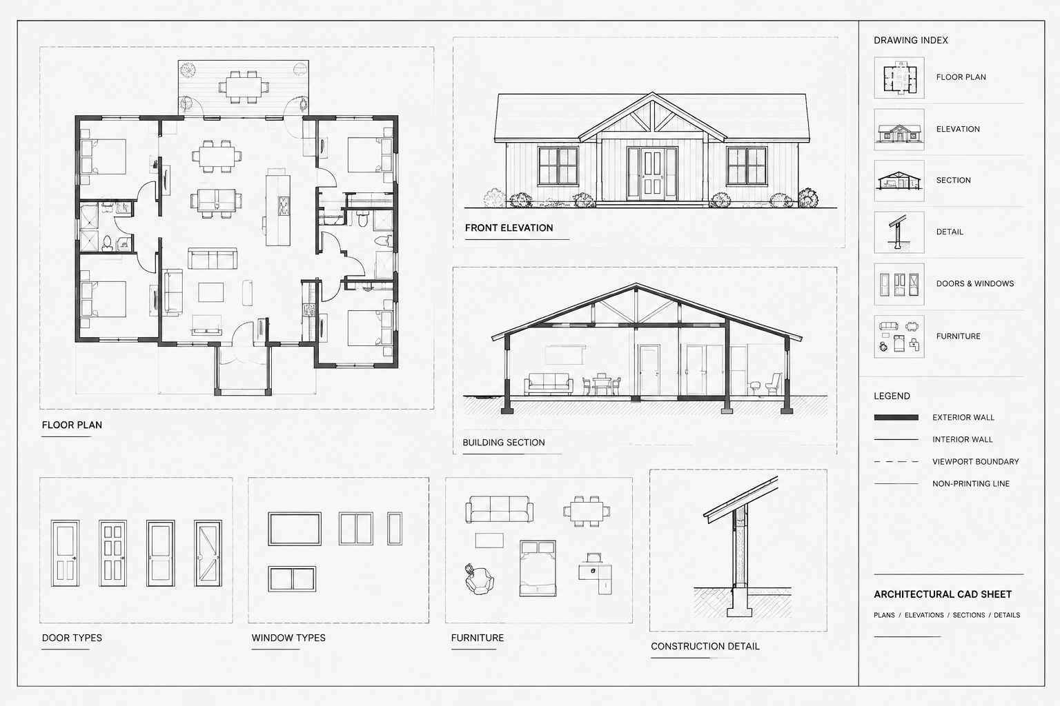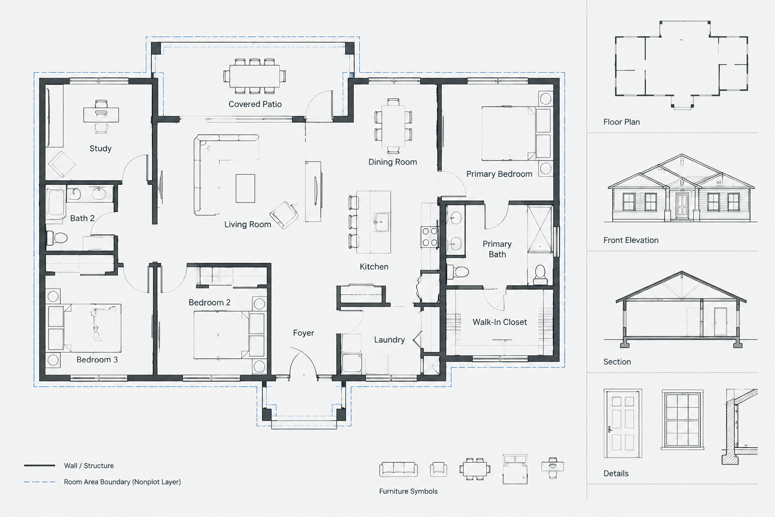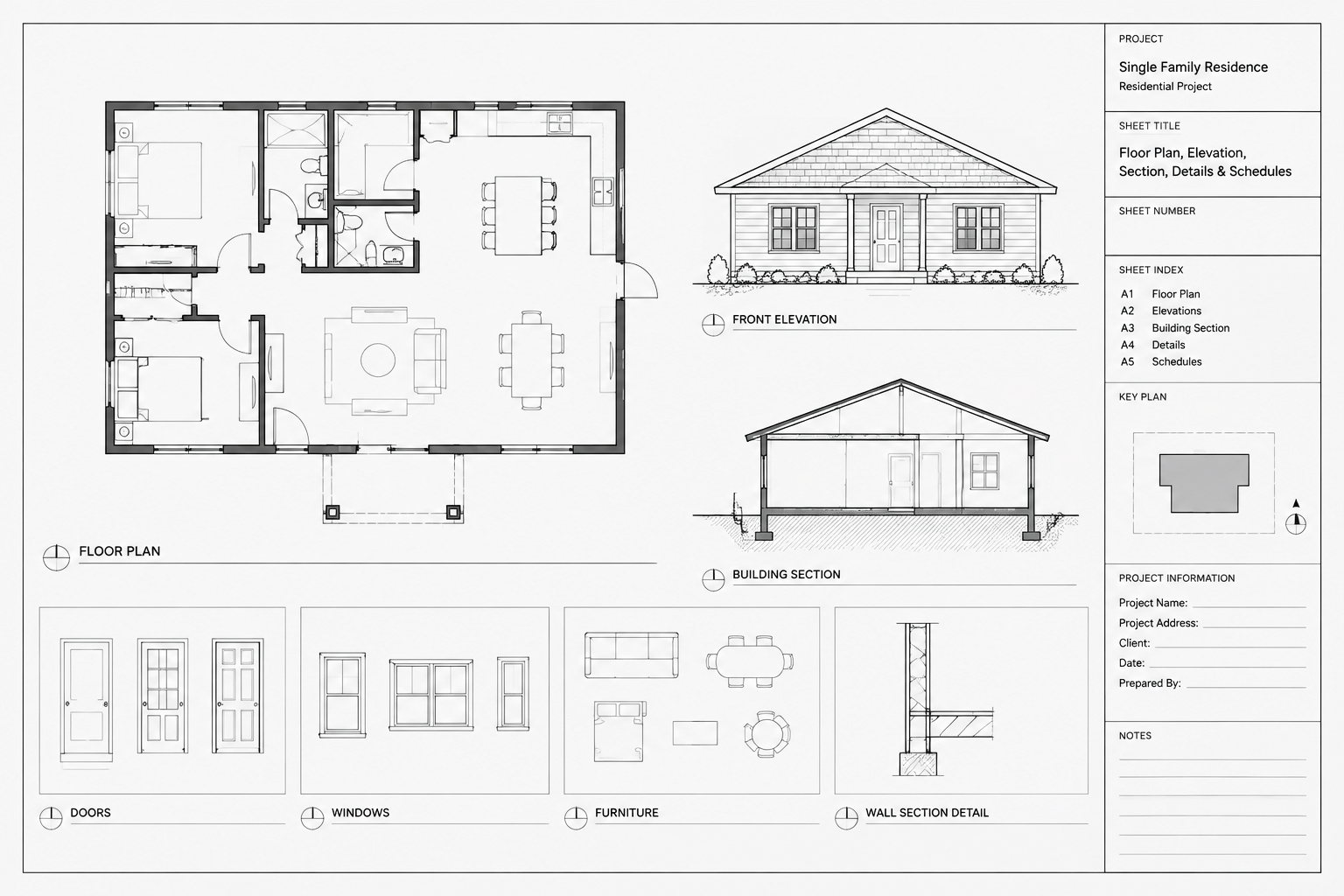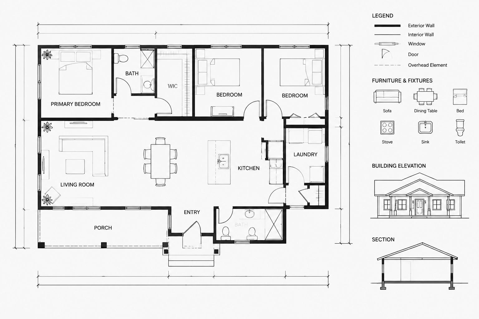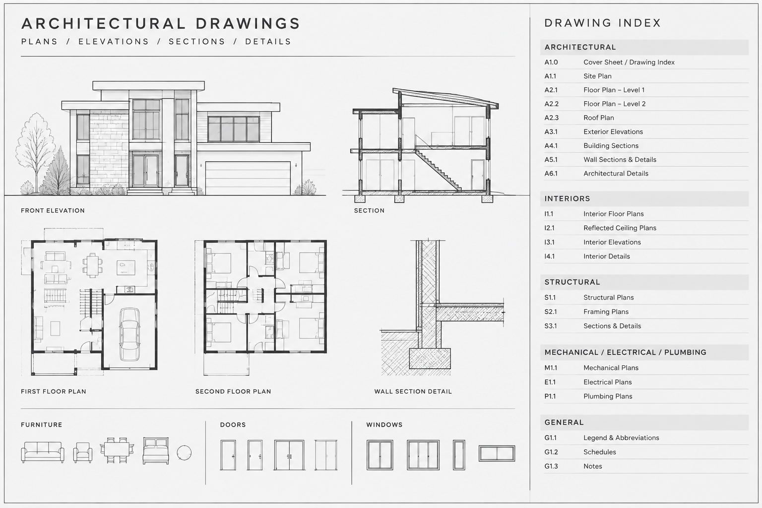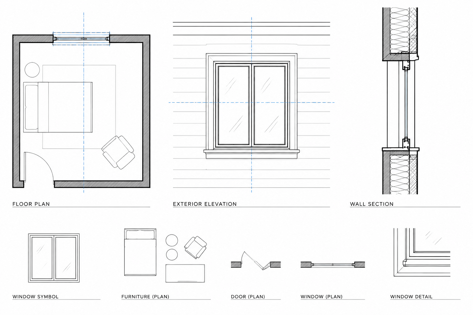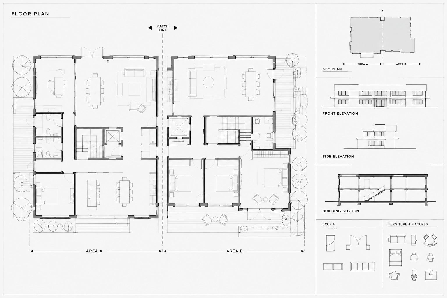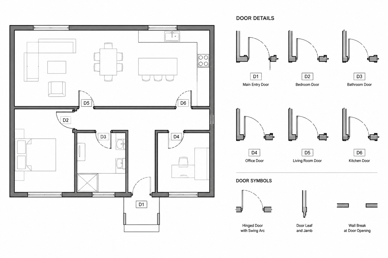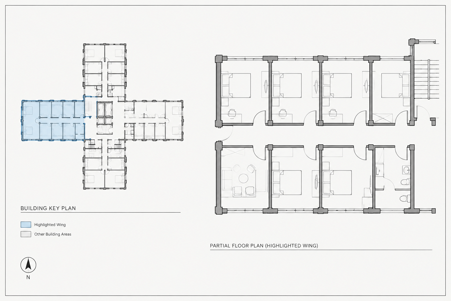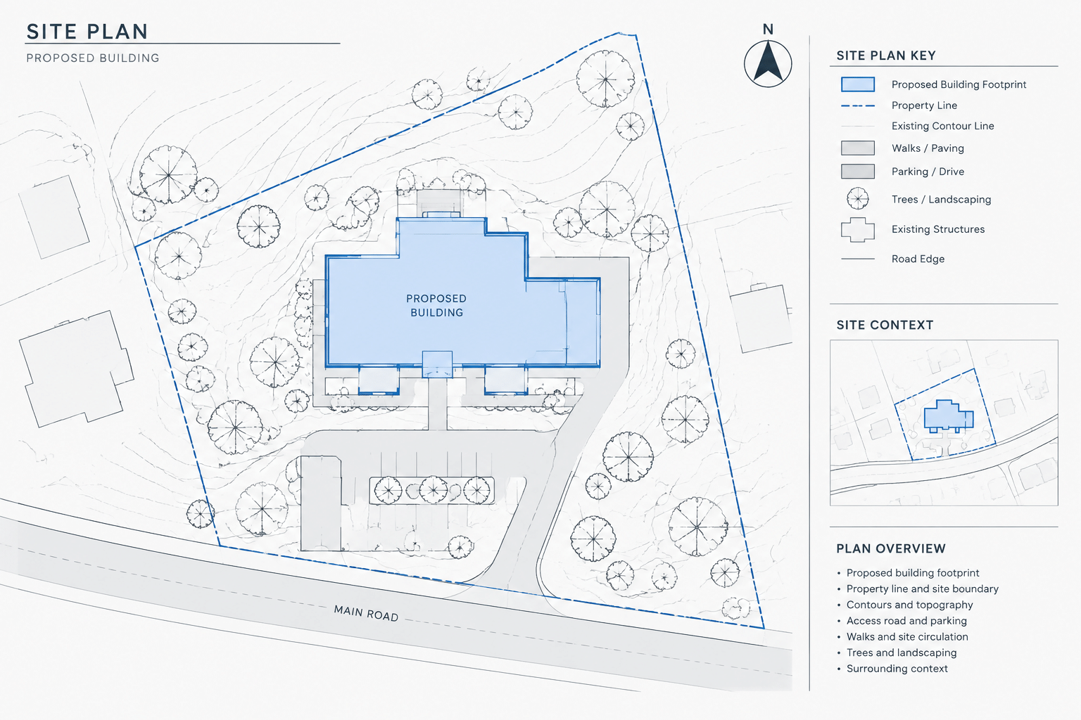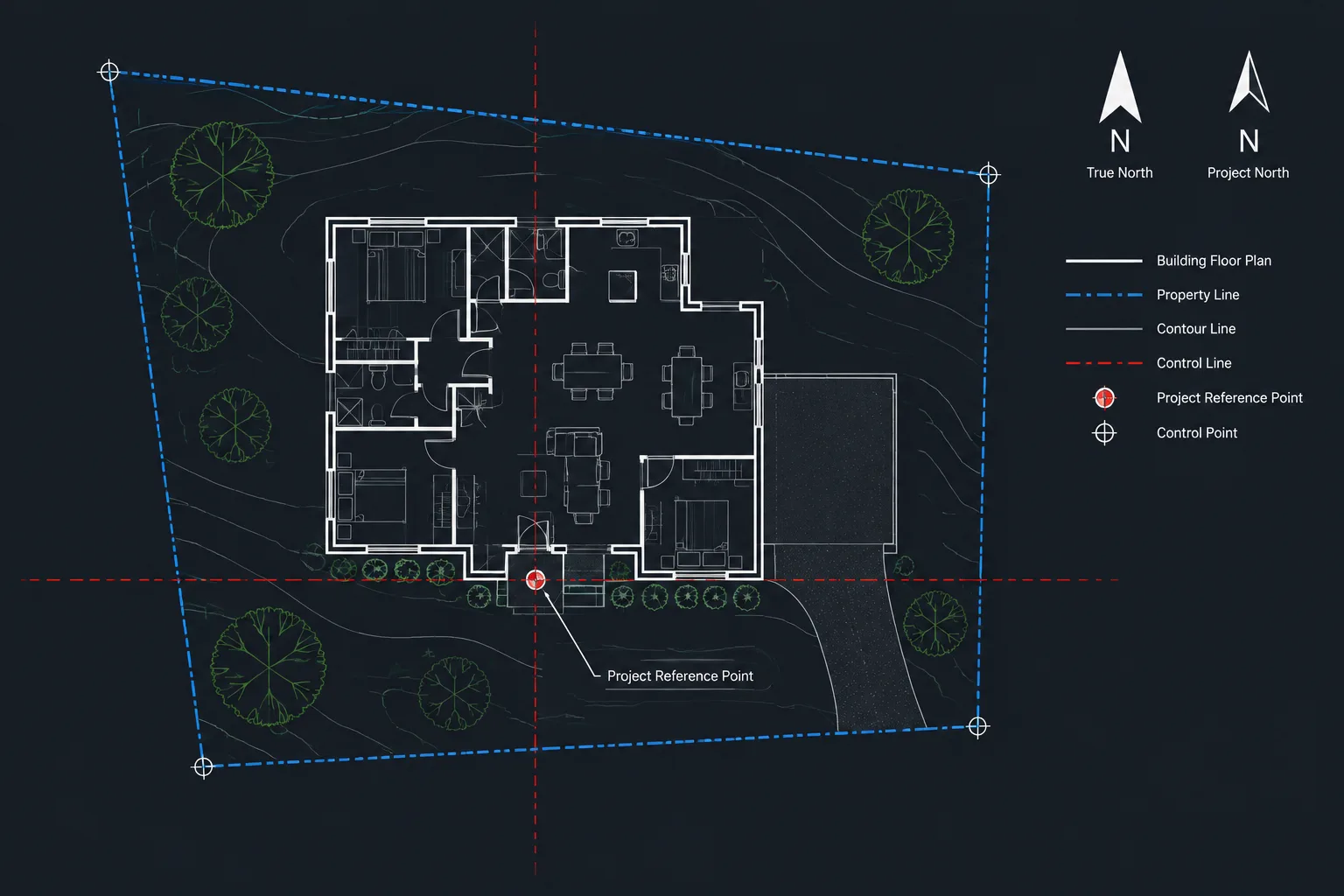
Coordinate problems in architectural CAD often remain hidden until multiple drawings are referenced together. A floor plan may look correct by itself while being displaced, rotated, or scaled incorrectly relative to the survey, structural model, or consultant background. Fixing the problem late can affect dimensions, site relationships, sheet views, and every dependent DWG file.
A dependable coordinate workflow establishes where the project is located, how the building is oriented, and how separate files align. It also distinguishes real project control from temporary drafting aids such as a rotated user coordinate system.
What Coordinate Control Needs to Define
Before drafting begins, the project team should be able to answer three basic questions:
- Where is the project reference point? This may be based on verified survey information, an agreed building control point, or another documented reference.
- Which direction defines the drawing orientation? Project north, true north, a property line, and the building’s main axis are not necessarily the same.
- How will separate files align? Every architectural and consultant drawing needs a repeatable insertion method rather than visual placement.
These decisions should be recorded in the project CAD standards or drawing setup notes. A coordinate system that exists only in one drafter’s memory is not reliable project control.
| Control item | Purpose | Typical risk if undefined |
|---|---|---|
| Horizontal reference | Locates plans in the drawing plane | Referenced files appear displaced |
| Drawing orientation | Relates the building to project or true north | Plans are rotated inconsistently |
| Drawing units | Controls the interpretation of referenced geometry | Files attach at the wrong scale |
| Insertion method | Defines translation, rotation, and scale behavior | Users manually adjust each reference |
| Vertical datum | Relates elevations and levels to an agreed reference | Plan coordinates and elevation values become confused |
Choose a Coordinate Strategy Before Building the File Set
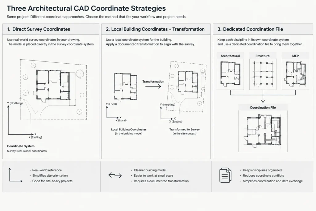
There is no single coordinate arrangement that suits every project. The correct choice depends on survey data, consultant requirements, project extent, and office workflow. Common approaches include the following.
Draft directly at verified survey coordinates
In this approach, project geometry remains in the same horizontal coordinate framework as the survey. It can simplify overlay checks because architectural and civil information share a common location. However, the team still needs a practical method for drafting a building that is rotated relative to the drawing axes.
Use local building coordinates with a documented transformation
A local origin can make architectural drafting easier by placing the building near the drawing origin and aligning its primary walls with convenient axes. The relationship to survey coordinates must then be controlled through a verified translation and rotation. That transformation should be documented and tested rather than recreated manually whenever files are exchanged.
Use a dedicated coordination file
A controlled master file can contain the survey reference, building placement, orientation markers, and other shared control geometry. Architectural files can be referenced into this file for coordination. This can be effective when the team protects the master file from casual editing and clearly identifies which file governs placement.
Avoid mixing these strategies without a defined reason. For example, one floor plan should not use local coordinates while another uses survey coordinates unless their relationship is deliberately managed.
A Step-by-Step Project Coordinate Workflow
1. Start with verified base information
Obtain the current project base files and confirm their source, units, coordinate status, and drawing orientation. Do not assume that a file is georeferenced merely because its geometry is far from the drawing origin. Likewise, do not assume that a north arrow proves the file is correctly rotated.
If several survey or civil files are available, identify which one governs. Archived or exported backgrounds may not retain the same setup as the current coordination file.
2. Establish visible control geometry
Create a small set of clearly labeled control objects in a protected file or dedicated layers. Depending on the project, these may include a project reference point, building control lines, property references, north indicators, and alignment lines shared with consultants.
Control geometry should be easy to inspect but difficult to edit accidentally. It should not be buried among walls, furniture, hatches, or annotation.
3. Record units, orientation, and insertion expectations
Document the intended drawing units and whether project files are expected to attach without additional scaling or rotation. If a transformation is required, identify where it is managed. Repeatedly typing an insertion point and rotation angle from memory invites inconsistency.
Do not use scaling as a substitute for correcting a unit mismatch. Determine why the mismatch exists before modifying project geometry.
4. Place the building without altering the governing survey
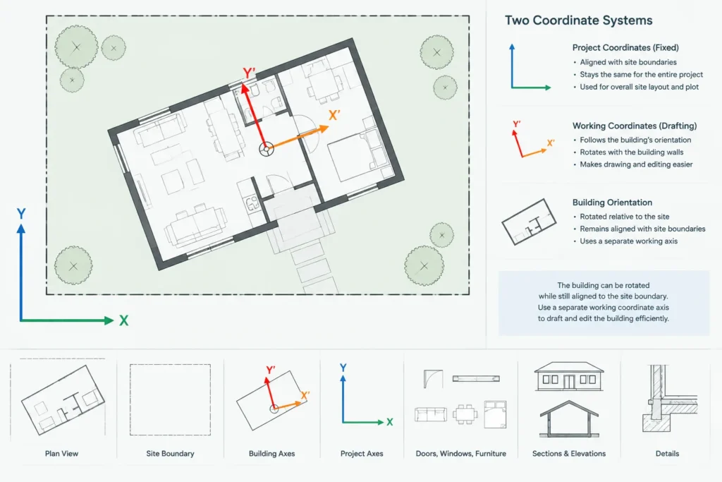
The architectural model should be positioned relative to the approved base information. Avoid moving or rotating the survey simply to make the building easier to draw. That may create a background that looks convenient but no longer aligns with the original civil information.
If the building is angled, retain the verified project relationship and use drafting tools that support an alternate working orientation.
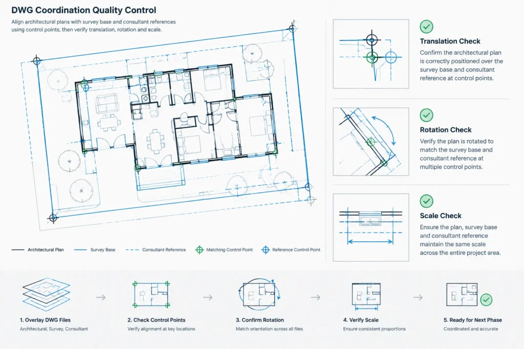
5. Test the alignment with independent references
Do not rely on a single point as proof of correct alignment. Check at least one additional known relationship, such as a distant control point, property feature, grid intersection, or recognizable survey element. A file can match at one point while still having the wrong rotation or scale.
Attach the relevant files using the agreed method, reload them, and repeat the test. This helps expose references that were aligned visually but not placed through repeatable coordinates.
6. Protect the established setup
Once verified, restrict changes to the control file and coordinate-defining geometry. If the building placement changes during design, update the authoritative location once and communicate the revision. Individual users should not independently shift copies of the same plan.
World Coordinates, User Coordinates, and View Rotation
In AutoCAD terminology, the world coordinate system provides the fixed underlying coordinate framework. A user coordinate system can establish a convenient working plane and axis direction for drafting. Changing the user coordinate system does not, by itself, move the project geometry.
This distinction is important for rotated buildings. A drafter can work orthogonally along the building’s main walls while the model remains correctly positioned relative to the survey. A rotated view can also improve plan readability without redefining the actual project location.
Name and document important working orientations when the file setup supports them. Avoid leaving an unexplained temporary orientation active for the next user.
Project North and True North Are Different Controls
Project north is commonly used to orient drawings conveniently on sheets, while true north communicates geographic direction. Their graphic relationship must remain consistent across site plans, floor plans, roof plans, and diagrams.
Rotating a viewport for sheet presentation should not be confused with rotating model geometry. Before changing either, determine whether the goal is to improve sheet orientation, simplify drafting, or revise the actual building placement.
How Downloaded CAD Blocks Fit into the Coordinate System
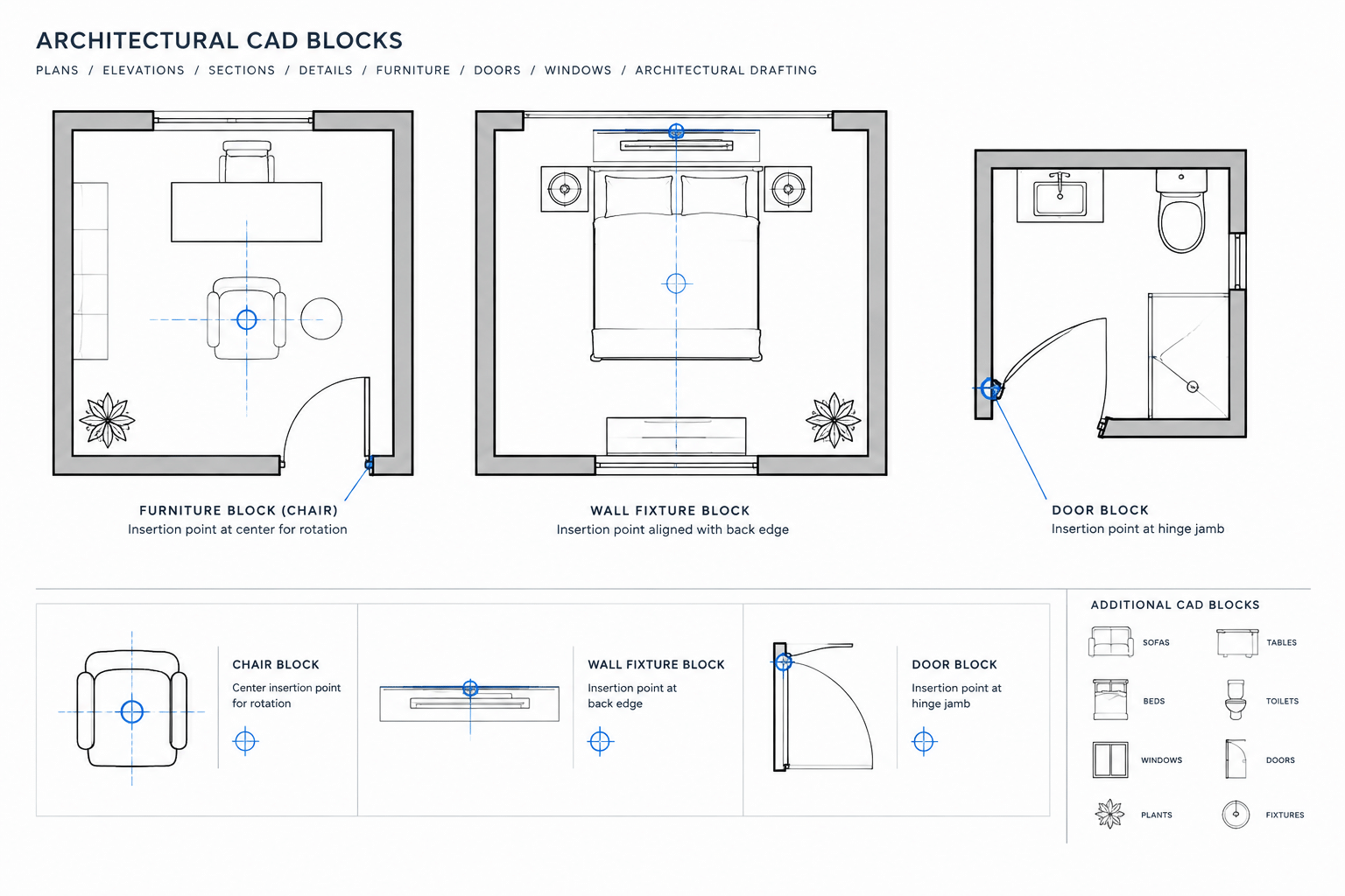
Furniture, fixtures, symbols, and other reusable blocks should normally be authored around a sensible local insertion point. They should not carry project survey coordinates merely because they were extracted from a coordinated drawing.
Before adding downloaded DWG content to a project, inspect its units, insertion point, layers, and hidden geometry. Insert the cleaned block into the architectural model; do not move the entire project to accommodate the block. If pasted content suddenly changes the drawing extents, check for remote objects or an unsuitable block origin.
Common Coordinate Failures
- Eyeballing external references: A file is moved until it appears close enough instead of using verified control.
- Using scaling to force a match: This can conceal a unit error and affect dimensions throughout the file.
- Moving the survey background: The architectural plan looks convenient, but coordination with civil information is lost.
- Confusing the drawing origin with a project benchmark: Horizontal coordinates and vertical elevation control serve different purposes.
- Rotating model geometry for sheet layout: A presentation problem is solved by changing coordinated project geometry.
- Keeping unexplained duplicate bases: Team members reference different versions that no longer share the same placement.
- Checking only one alignment point: Translation may appear correct even when rotation or scale is wrong.
Coordinate Quality-Control Checklist
- Confirm the governing base file and its drawing units.
- Identify the approved horizontal reference and drawing orientation.
- Keep control geometry separate from ordinary design content.
- Use a repeatable reference insertion method.
- Verify alignment at more than one location.
- Distinguish model placement from viewport rotation.
- Document any local-to-survey transformation.
- Check consultant files before issuing updated backgrounds.
- Remove remote or unexplained geometry from imported content.
- Recheck coordinates after major building-placement revisions.
Good architectural CAD project coordinates are not simply a matter of placing the first floor plan at a convenient location. They are a shared framework for surveys, plans, consultant references, and sheets. Establishing that framework early—and making it visible, documented, and testable—reduces alignment errors throughout the DWG set.