Architectural CAD leaders and multileaders do more than connect text to linework. They help readers distinguish general information from notes that apply to a particular material, edge, assembly, or construction condition. Their effectiveness depends on clear targets, controlled styles, coordinated text, and careful placement.
This guide explains how to develop, place, edit, and review leaders as part of a consistent annotation workflow. It also addresses shared notes, drawing scale, imported styles, revision checks, and common readability problems found during sheet production.
Leaders connect architectural notes to the exact objects, materials, or conditions they describe. Although a leader may appear to be a simple arrow and line, inconsistent leader geometry can quickly make a drawing difficult to read. Crowded arrowheads, crossing lines, detached notes, and uncontrolled text formatting all weaken the visual hierarchy of a sheet.
A reliable architectural CAD leader workflow treats the note, leader line, arrowhead, landing, and scale behavior as one coordinated annotation system. The goal is not merely to make every leader look identical. The goal is to make each note easy to associate with the correct drawing element while keeping the sheet legible at its intended plotted scale.
What an Architectural Leader Communicates
A leader establishes a visual relationship between annotation and geometry. It can identify a material, point out a construction condition, connect a keynote to an assembly, or clarify an unusual feature that cannot be described efficiently with dimensions alone.
Leaders commonly appear in:
- Floor plan material and construction notes
- Exterior and interior elevations
- Building sections and wall sections
- Enlarged plans and construction details
- Reflected ceiling plans
- Roof plans and site-related drawings
- Demolition, renovation, and phasing drawings
A leader should identify a specific target. Notes that describe an entire room, elevation, or broad region may be clearer as general notes, labels, brackets, or keyed references instead of arrowed leaders.
Leader, Multileader, or Separate Text and Linework?
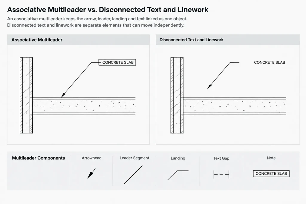
CAD users can construct a note using independent text, polylines, and arrowheads, but disconnected objects are harder to edit and easier to misalign. A dedicated leader or multileader object typically provides better control because its components remain associated.
| Method | Useful for | Main concern |
|---|---|---|
| Leader object | Simple annotation and legacy drawing compatibility | Formatting may depend on older drawing conventions |
| Multileader object | Repeatable notes, multiple arrows, and style-controlled annotation | Imported styles can create inconsistent results |
| Text with separate linework | Exceptional graphics that cannot be built with a standard leader | Components can separate during editing |
| Block-based callout | Keynote symbols, detail references, and repeated tagged conditions | Attributes, scale, and block definitions require coordination |
For routine architectural notes, an associative multileader is often more manageable than loose text and lines. Separate geometry should be reserved for cases where the standard annotation object cannot communicate the condition clearly.
Build a Controlled Leader Style
A leader style should be established in the project template rather than recreated in individual drawings. The style coordinates the appearance of the arrow, leader segments, landing, text, and spacing around the note.
Coordinate the text component
Assign an approved project text style and confirm that the text height behaves correctly in the project’s annotation system. Avoid manually resizing individual notes to make them fit. If a note is too large for the available space, first consider editing the wording, changing the note location, or selecting a more appropriate drawing scale.
Text alignment should also be predictable. Notes placed to the right of a target generally read best when the text begins near the landing. Notes placed to the left need corresponding alignment so the landing meets the text block cleanly rather than extending through it.
Select an appropriate arrowhead
The arrowhead should remain visible without overpowering the linework it identifies. A project may use filled arrows, open arrows, dots, or other endpoint symbols for different annotation purposes. Do not mix endpoint types casually. If symbols have distinct meanings within the drawing set, document those meanings in the office template or annotation guide.
Control the landing and text gap
A short horizontal landing can make the relationship between a leader and its note easier to read. The gap between the landing and text should be consistent, but it should not be so large that the note appears disconnected. Review this spacing in a plotted test rather than judging it only at a close on-screen zoom.
Use layers intentionally
Place leaders on a defined annotation layer or on discipline-specific note layers established by the project. Avoid using object layers such as walls, doors, or furniture simply because the leader points to those objects. Annotation layers provide better control over plotting, viewport visibility, and drawing cleanup.
Place Leaders for Fast Visual Reading
Good leader placement reduces the amount of visual tracing required from the note to its target. The reader should not have to follow a line through several intersections or guess which nearby object the arrowhead identifies.
- Point to a visible edge, surface, joint, or symbolic representation of the noted item.
- Avoid terminating an arrowhead in empty space unless the note clearly applies to an area.
- Keep arrowheads away from dimensions, grid bubbles, section marks, and other high-priority symbols.
- Limit crossings between leaders and drawing geometry where practical.
- Avoid running a leader parallel to nearby linework when the two could be mistaken for one another.
- Keep notes outside dense construction geometry when space permits.
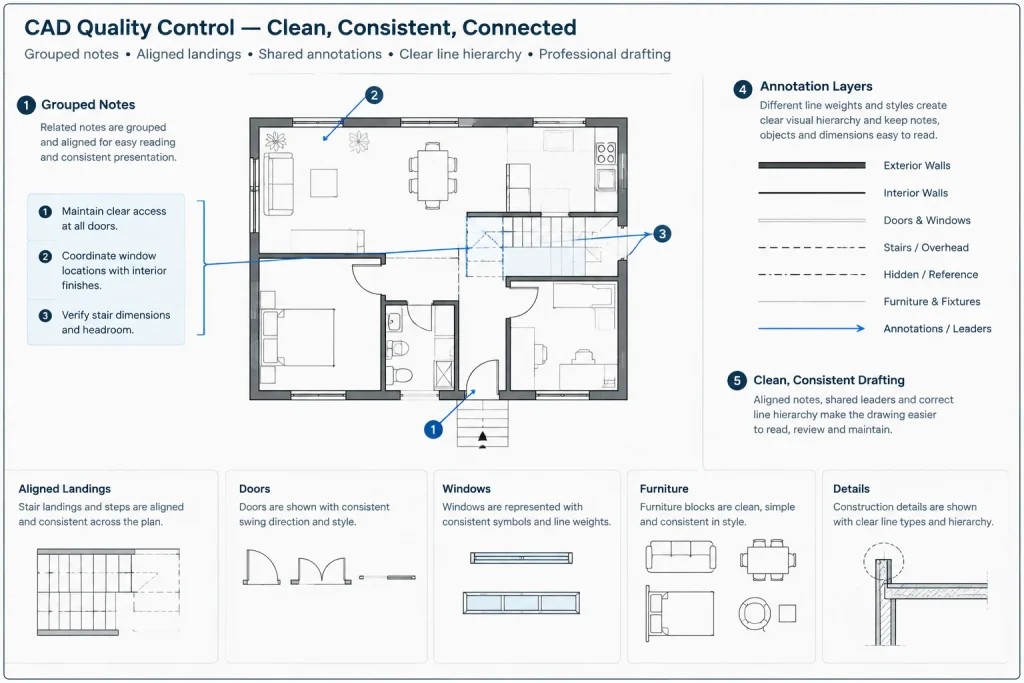
- Align groups of related notes to create an orderly annotation zone.
Diagonal leader segments are often easier to distinguish from orthogonal building geometry. However, a rigid rule requiring every leader to use the same angle can create unnecessary line crossings. Consistency should support clarity rather than override it.
Coordinate Multiple Leaders and Shared Notes
A single note may apply to several identical or related conditions. A multileader can connect one text block to multiple targets, reducing duplicate text. This is useful only when every arrow clearly refers to the same note.
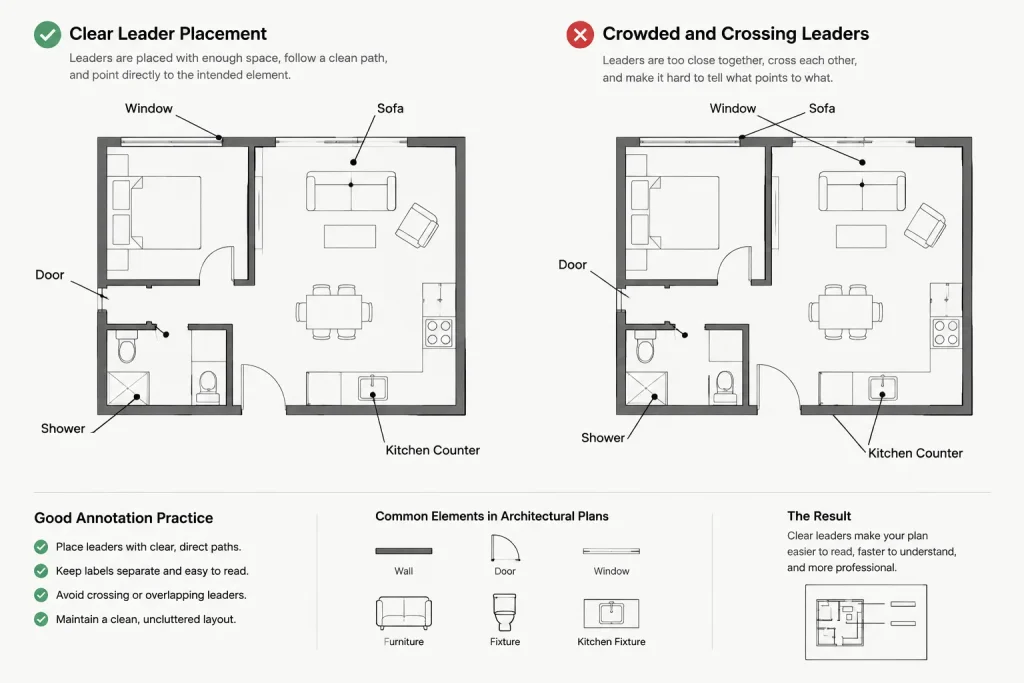
Do not combine unrelated conditions under one note merely to reduce annotation. If one target later changes, a shared note can become misleading. Separate notes are safer when materials, installation conditions, extents, or responsibilities may differ.
When multiple arrows connect to one note:
- Confirm that all targets represent the same condition.
- Arrange the arrows so they do not cross one another.
- Keep the shared text close enough to the group to show the relationship.
- Review the note after plan revisions, substitutions, and detail updates.
- Delete obsolete arrow branches rather than leaving them pointed toward removed geometry.
Use Concise, Coordinated Note Text
A leader does not compensate for vague wording. Notes should identify the condition directly and avoid unnecessary repetition. Use consistent project terminology for materials, assemblies, rooms, equipment, and references.
If a specification, schedule, or detail contains the full requirement, the leader note can direct the reader to that coordinated source rather than repeating a long description. Repeated information can drift out of alignment when revisions occur. At the same time, a reference should be specific enough that the reader can locate the related information without guessing.
Avoid informal abbreviations unless they are established in the drawing set. Also avoid embedding unverified code conclusions, performance claims, or product requirements in a standard note. Project-specific technical language should be reviewed by the responsible design professional.
Manage Scale and Annotation Context
Leader graphics must be evaluated at the final sheet scale. An arrow and landing that look balanced in model space may become oversized, undersized, or crowded in a viewport.
Projects commonly handle annotation with model-space scaling, annotative objects, paper-space annotation, or a controlled hybrid method. Whichever system is used, apply it consistently. Check that the leader, text, and related symbols respond together when viewport scales change.
Copying leaders between files deserves special attention. The destination drawing may contain a style with the same name but different properties, or imported content may bring an unwanted style definition. After copying, verify text appearance, arrow size, layer assignment, landing behavior, and plotted output.
Edit Leaders Without Breaking Their Meaning
Plan revisions often move walls, fixtures, equipment, and details while leaving annotations behind. A leader can remain graphically intact yet point to the wrong object. For that reason, annotation review must be part of every geometry revision.
When editing a leader:
- Move the arrow endpoint to the revised target rather than stretching the line approximately.
- Check whether the note still applies after the design change.
- Maintain the established landing and text alignment.
- Remove extra vertices that create awkward bends.
- Avoid exploding the leader unless there is a documented need.
- Confirm that moved notes do not cover dimensions, tags, or reference symbols.
Exploded leaders may look correct initially, but they lose much of the behavior that makes annotation manageable. They also make later style changes and cleanup more difficult.
Quality-Control Checklist
Review leaders both in the DWG and in the plotted PDF. The PDF reveals spacing and hierarchy problems that may be difficult to notice while zooming through model space.
- Does every arrow point to a clear and current target?
- Is the note on the correct annotation layer?
- Does the text use the approved project style?
- Are arrowheads and landings visually consistent?
- Are any leaders crossing dimensions, tags, or one another?
- Do shared notes genuinely apply to every connected target?
- Are references to details, schedules, or sheets still correct?
- Are any notes duplicated or contradicted elsewhere?
- Is the annotation legible at the intended plotted scale?
- Did copied content introduce unwanted leader or text styles?
A Practical Leader Workflow
Begin with a small set of project-approved leader styles in the CAD template. Assign each style a defined purpose, such as general notes, keynote symbols, or detail annotations. Draft notes near their targets, then organize them into readable groups while maintaining clear arrow paths. Use shared notes selectively, and review all leader endpoints whenever the underlying geometry changes.
Before issuing a sheet, inspect the annotation at plot scale and compare related drawings. Consistent architectural CAD leaders should quietly guide the reader through the information. When the leader system is working well, the drawing feels organized, references are easy to follow, and the annotation supports the design instead of competing with it.
Troubleshooting Leader Problems in Existing Drawings
When inherited or consultant-provided drawings contain inconsistent leaders, begin by diagnosing the annotation system before correcting individual notes. Similar-looking objects may use different leader styles, text styles, layers, or scale behavior. Editing their appearance one at a time can hide the underlying inconsistency without resolving it.
Check object type before editing
Determine whether each note is a leader, multileader, block-based callout, or collection of separate objects. This affects how the note responds to style updates, grips, copying, and later revisions. Loose text and linework may need special handling because their visual relationship is not maintained automatically.
Separate style problems from placement problems
An incorrect arrowhead, text style, landing, or text gap usually indicates a style or property problem. A line crossing a dimension or pointing ambiguously between nearby objects is primarily a placement problem. Treating these as separate issues makes cleanup more systematic and reduces unnecessary overrides.
Review overrides carefully
A leader can belong to an approved style while carrying object-level changes that make it look different. Before replacing an entire style, check whether isolated overrides are causing the inconsistency. Preserve intentional exceptions only when they improve communication and remain understandable to future editors.
Confirm layer and visibility behavior
If a note appears in one viewport but not another, review its layer assignment and annotation context before recreating it. Also confirm that the note has not been placed on a geometry layer whose visibility is controlled for reasons unrelated to annotation.
Coordinate Leaders During Team Handoffs
Leader quality can deteriorate when several people edit the same drawing set without a shared annotation method. A practical handoff should identify the approved styles, their intended purposes, the annotation layers, and the project method for handling scale. This allows another drafter to revise notes without relying on visual imitation.
Before exchanging files, remove obsolete notes, resolve detached endpoints, and check that referenced details or schedules still exist. After receiving updated backgrounds or revised geometry, review leaders by area rather than assuming their associations remain correct. The critical question is not whether a leader still looks intact, but whether it still communicates the intended condition.
Use Plot Review as an Annotation Test
On-screen inspection is useful for finding detached objects and incorrect layers, but plotted review reveals the actual reading sequence of a sheet. Look for notes that merge into dense linework, arrowheads that compete with symbols, landings that appear detached from text, and leader paths that require excessive visual tracing.
Review related views together. If the same condition is described differently in a plan, elevation, and detail, the issue may be terminology or coordination rather than leader geometry. Resolving that discrepancy improves the drawing set more than adjusting the appearance of a single callout.
Frequently Asked Questions
What is the difference between a leader and a multileader?
A leader provides an annotation path from a note to a target. A multileader is designed to manage the text or symbol, landing, arrow, and potentially multiple leader branches as a coordinated object. The exact behavior depends on the drawing setup and CAD application.
When should one note use multiple arrows?
Use multiple arrows only when every target shares the same condition and wording. Separate the notes when materials, extents, responsibilities, or installation conditions could differ.
Should leaders point to the center of an object?
Not automatically. The clearest target may be an edge, surface, joint, hatch area, or symbolic component. Choose a point that makes the note’s intended scope unambiguous.
Why do copied multileaders change appearance?
The destination file may use different definitions for leader styles, text styles, layers, blocks, or annotation behavior. Inspect copied notes in the receiving drawing and verify their plotted appearance rather than assuming a matching style name means matching properties.
Should a leader be exploded to make it easier to adjust?
Usually not. Exploding separates coordinated annotation components and makes later style changes, movement, and quality control more difficult. Reserve separate linework for unusual graphics that cannot be communicated clearly with the standard annotation object.
Are diagonal or orthogonal leader lines better?
Neither is universally better. Diagonal segments can stand apart from orthogonal building geometry, while controlled horizontal landings can support orderly text alignment. Choose the path that reaches the target clearly without creating crossings or visual confusion.
How should leaders be checked after a plan revision?
Review the endpoint, note wording, target condition, text location, and nearby annotation. A leader may remain visually complete even when the object it once described has moved or changed.