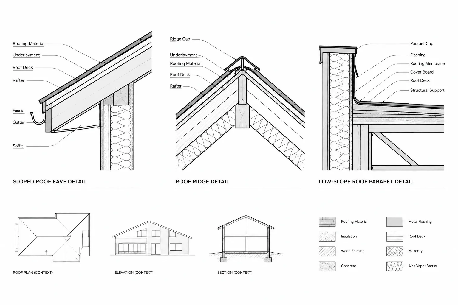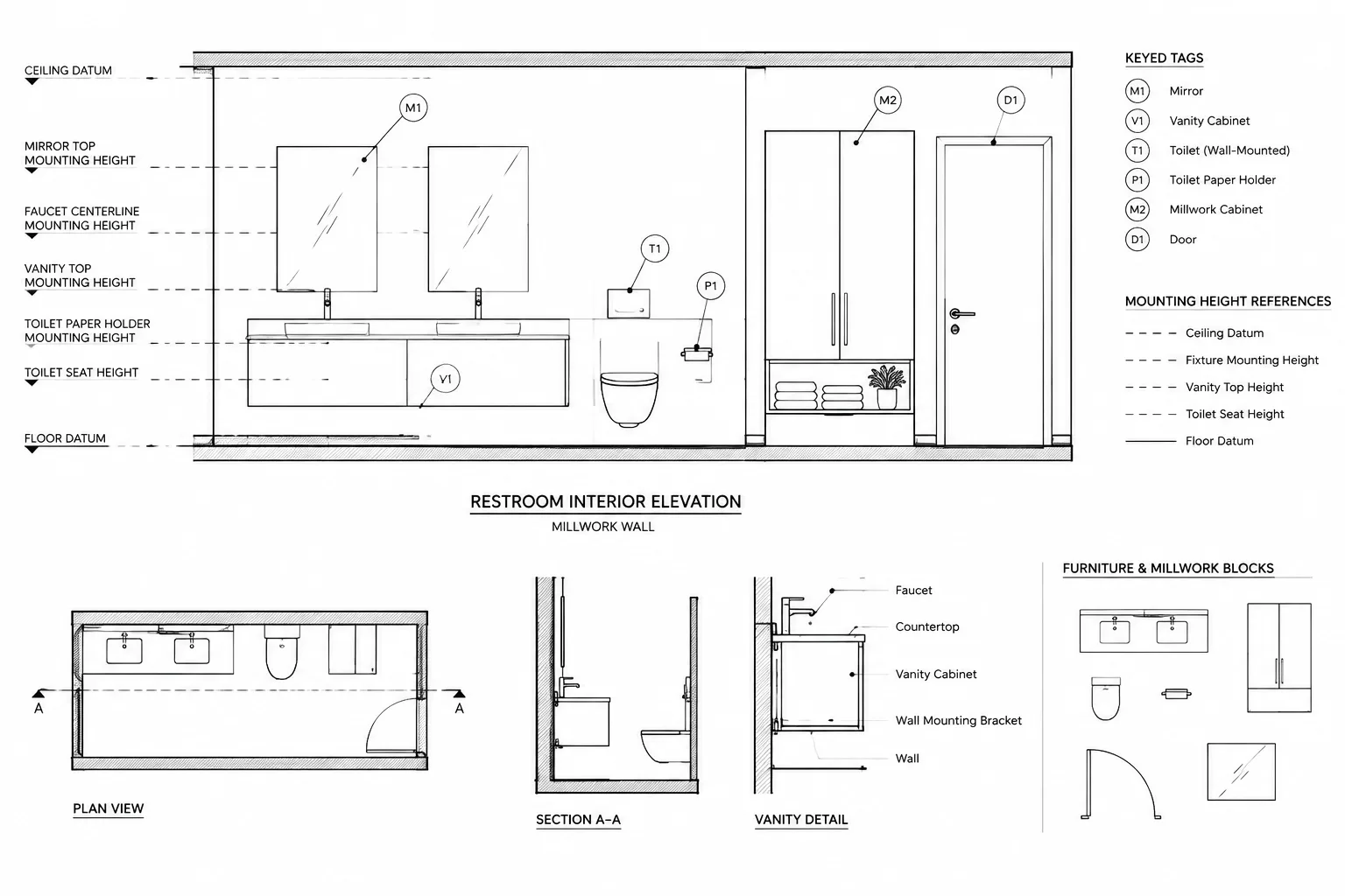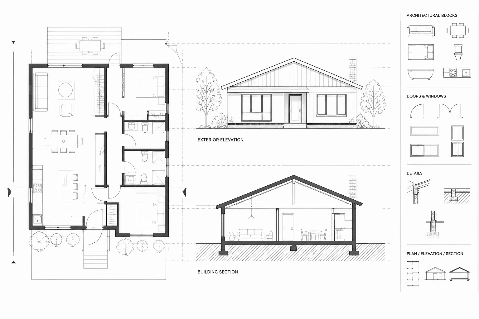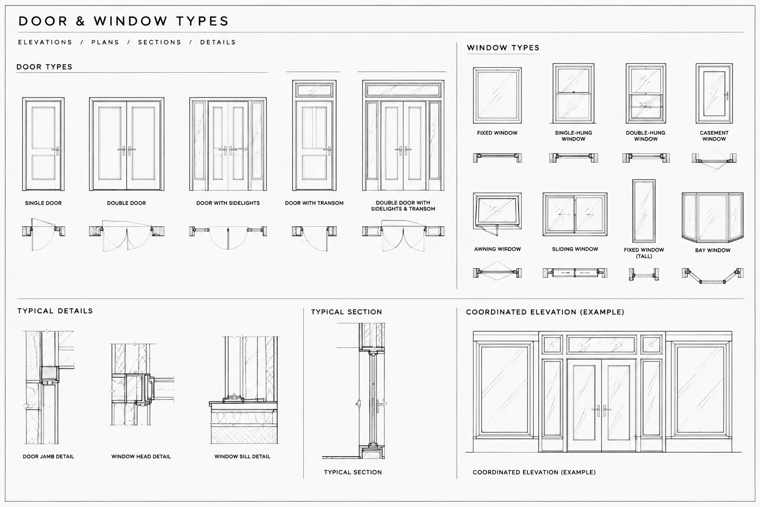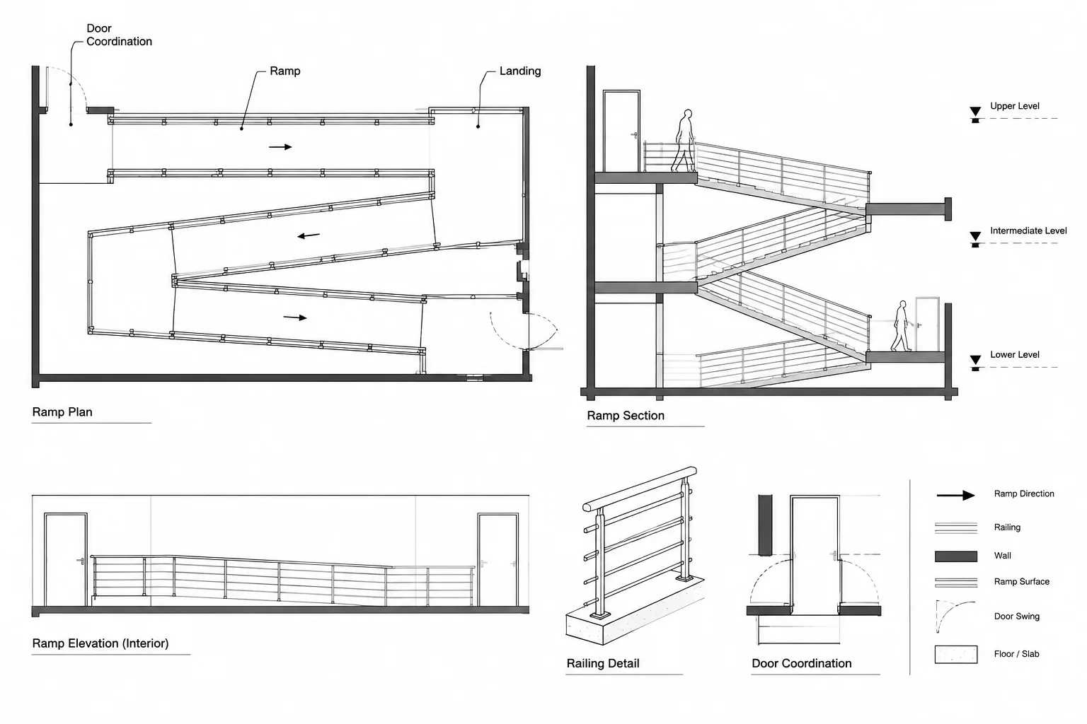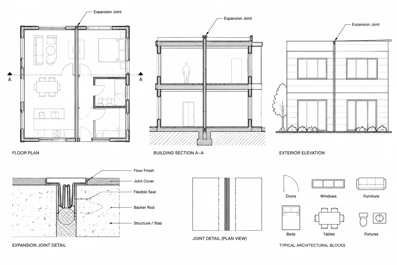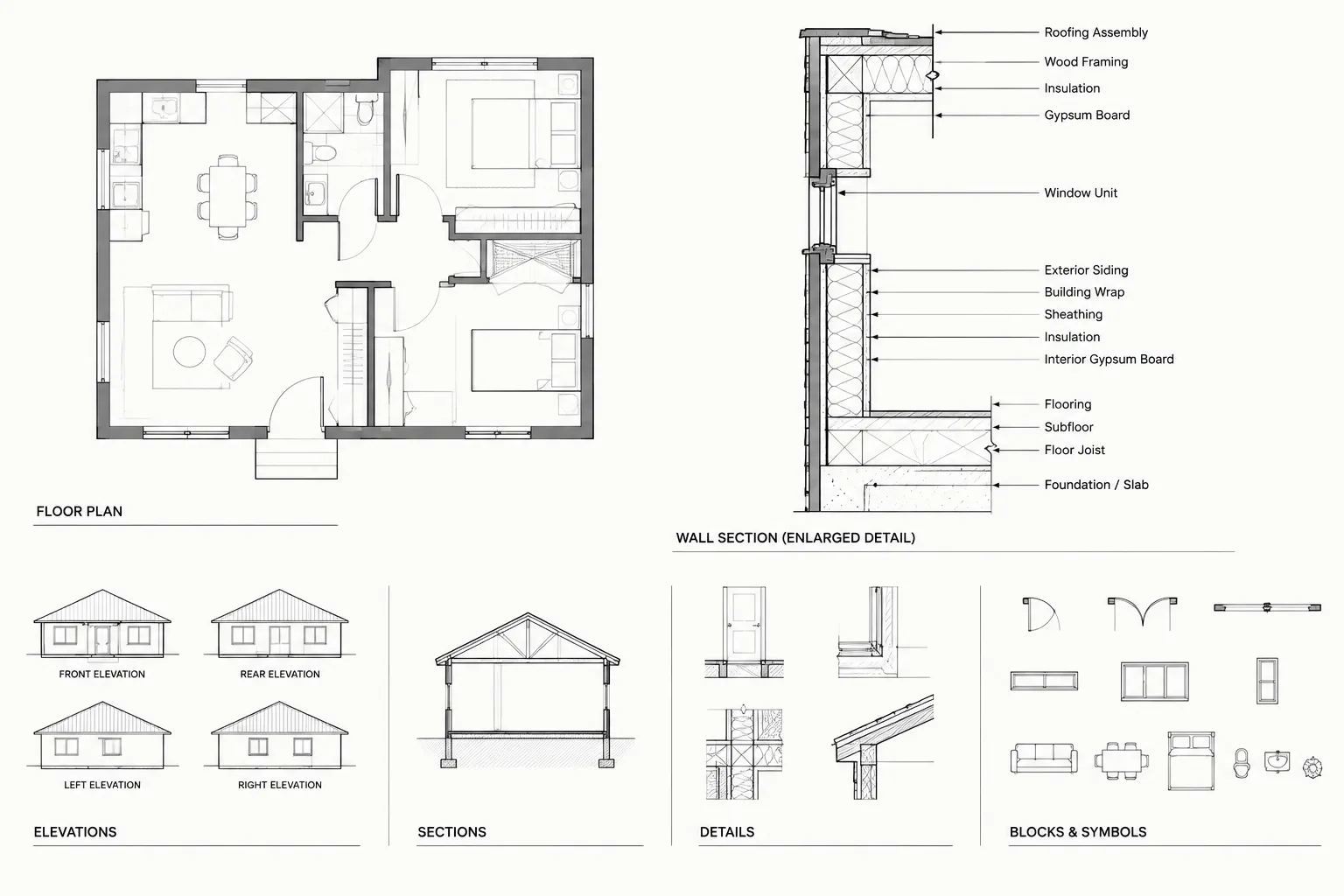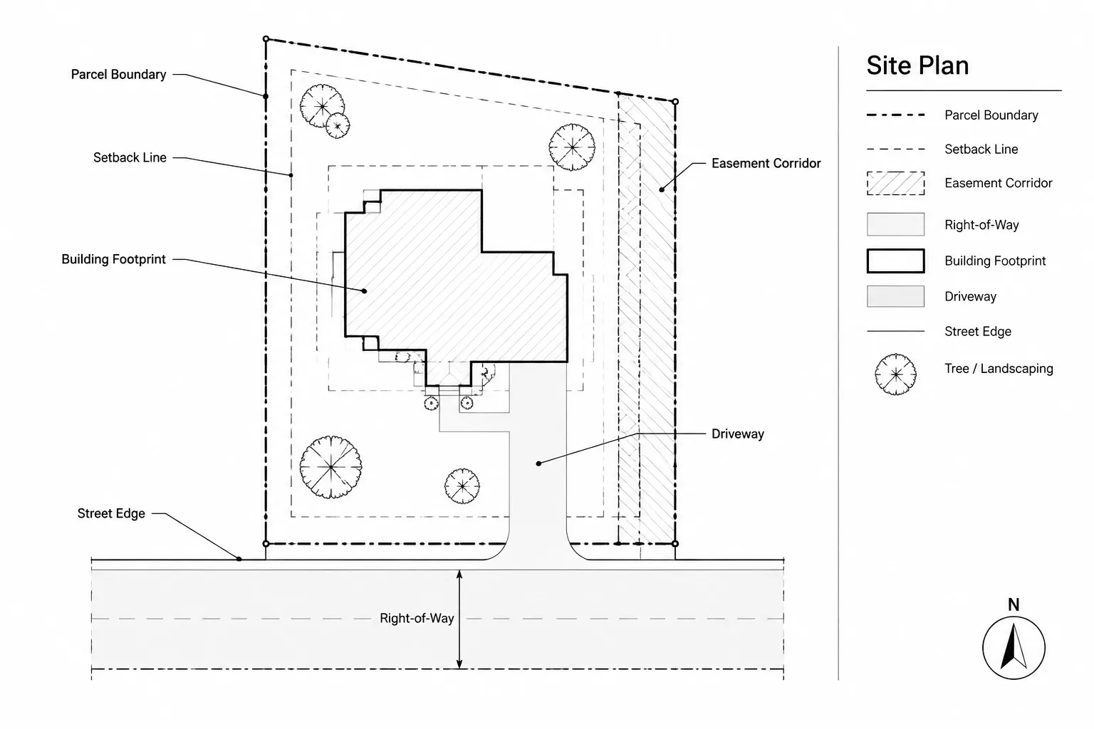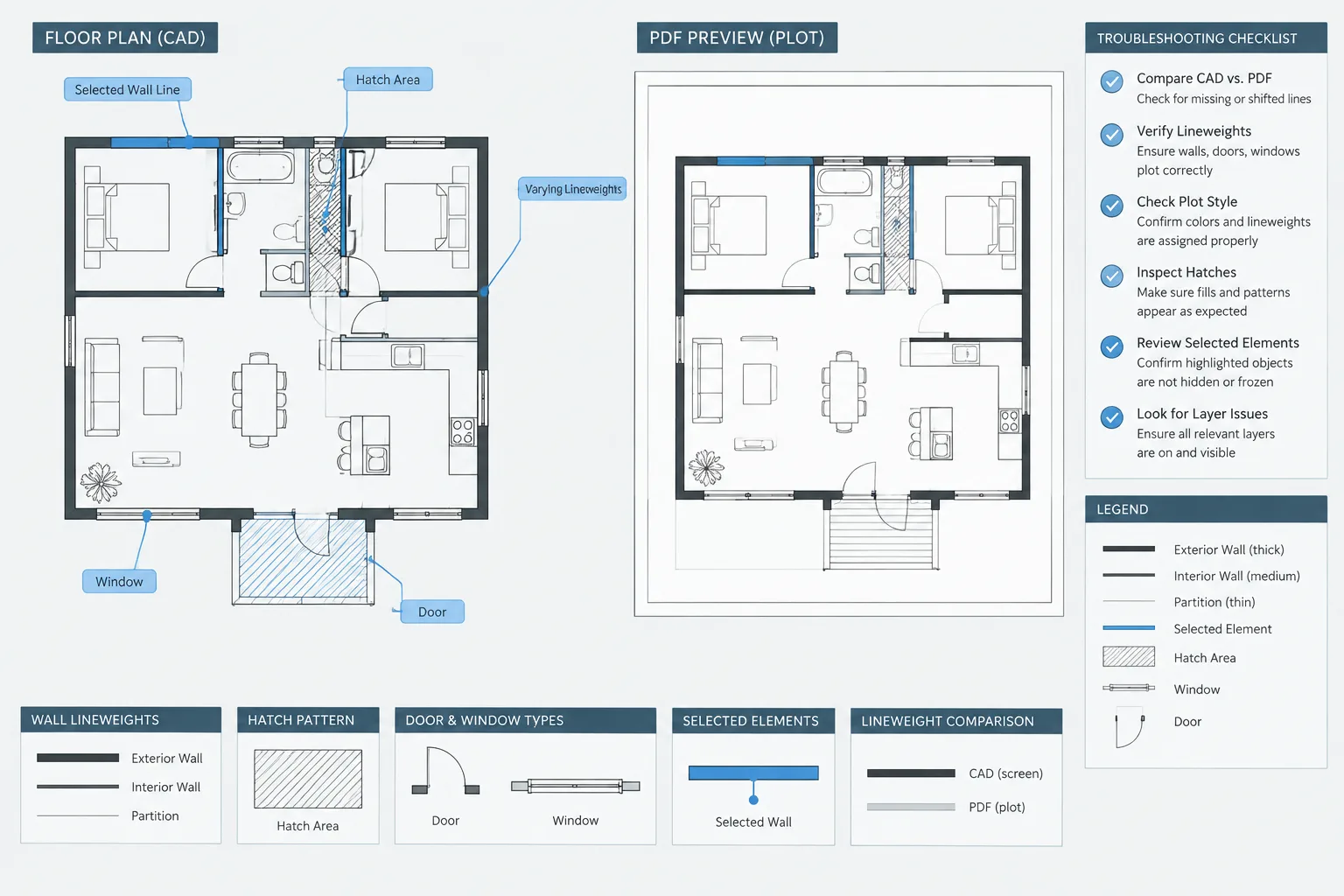
Missing geometry and incorrect lineweights in a plotted PDF do not always originate in the same part of a CAD workflow. The fault may follow an individual object, a layer, a viewport, a layout, or the final output process. Effective CAD PDF lineweight troubleshooting therefore begins by locating the stage where the drawing changes rather than immediately editing plot settings.
The checks below provide a controlled method for tracing architectural linework from the DWG environment through plot preview and into the finished PDF. Use copies or limited test plots while diagnosing the issue, especially when the drawing relies on shared templates, external references, or office plot style files.
A drawing can look correct in model space and still produce a PDF with missing lines, unexpectedly heavy walls, faint annotations, or inconsistent hatch patterns. These problems are often blamed on the PDF printer, but the actual cause may be an object property, layer setting, viewport override, plot style, page setup, or display issue.
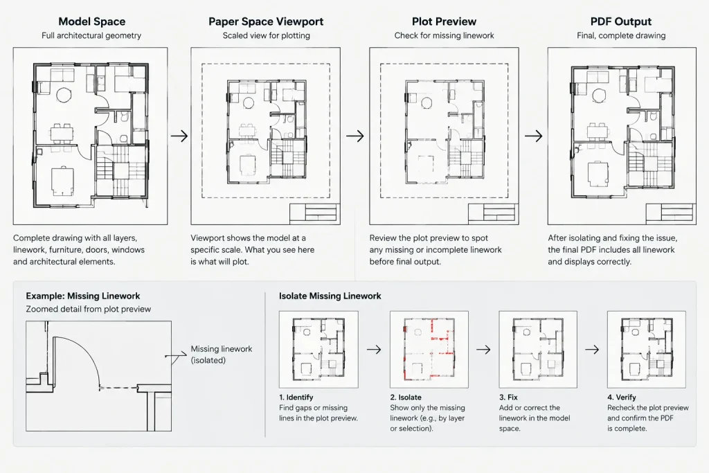
The fastest way to troubleshoot CAD PDF lineweights is to isolate where the graphic changes. Instead of repeatedly adjusting random settings, compare the object, layout, plot preview, exported PDF, and physical print in a controlled sequence. This workflow helps identify the source without disrupting the rest of the drawing set.
Start by Identifying the Exact Failure
Before editing the file, define what is wrong and where it occurs. A precise description is more useful than saying that the plot looks bad.
- Is the object completely absent or merely too light to see?
- Does the problem affect one object, one layer, one viewport, one layout, or every sheet?
- Is the line incorrect in plot preview, or only after the PDF is created?
- Does the PDF look wrong on screen but print correctly?
- Are model geometry, dimensions, text, hatches, and external references affected in the same way?
Test a small sample sheet when possible. It is easier to diagnose one wall, hatch, note, and reference file than an entire drawing package.
Use Plot Preview as the First Major Checkpoint
Plot preview separates many drawing and page-setup problems from PDF viewing problems. If the line is already missing or incorrect in preview, the cause is likely inside the DWG or its plotting configuration. If preview is correct but the exported PDF is wrong, investigate the selected output device, PDF settings, viewer, or downstream printing process.
Do not rely only on the layout display. A layout may show object colors and apparent line thicknesses that differ from the plotted result. Preview should be checked at a useful magnification because thin lines and dense patterns can disappear when the entire sheet is reduced to fit the screen.
Check the Object Before Changing Global Settings
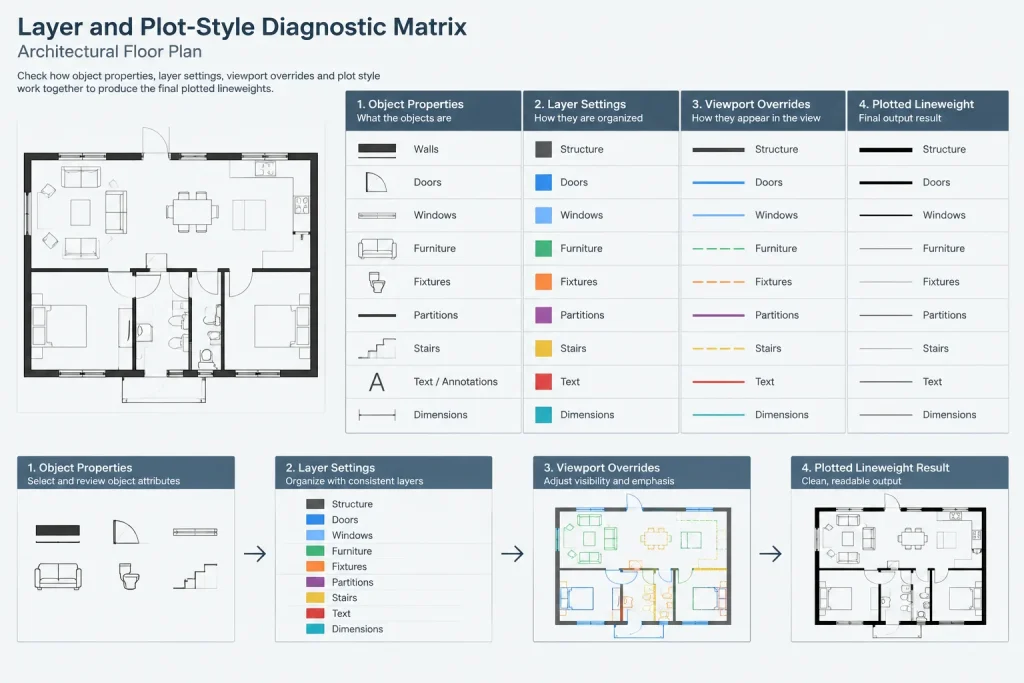
Select a problem object and inspect its basic properties. Confirm its layer, color, linetype, lineweight, transparency, and plot style behavior. Architectural drawings are usually easier to maintain when most objects inherit properties from their layers. Direct object overrides can make an isolated line plot differently from otherwise identical geometry.
If one object is wrong while neighboring objects on the same layer are correct, compare their properties. Common causes include:
- A direct color or lineweight override
- An object placed on an unintended layer
- A nonplotting layer used by mistake
- Unexpected transparency
- Duplicate geometry producing a heavier result
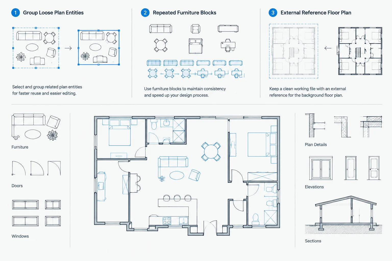
- A block component with internal properties that do not follow the insertion layer
Use a temporary test rather than immediately redefining office standards. For example, place a copy of the object on a known plotting layer and compare the preview. If the copy plots correctly, the issue is probably tied to the original layer or object properties.
Review Layer and Viewport Conditions
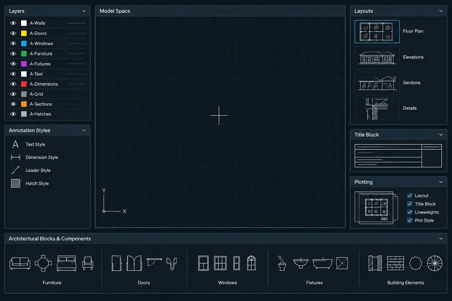
A layer can be visible in one context and absent in another. Check whether the layer is globally on and thawed, enabled for plotting, and active in the relevant layout viewport. A layer may also have viewport-specific color, linetype, or lineweight overrides.
Viewport overrides are especially important when one plan appears correct on one sheet but wrong on another. Compare the layer state inside each affected viewport rather than assuming the layouts use identical presentation settings.
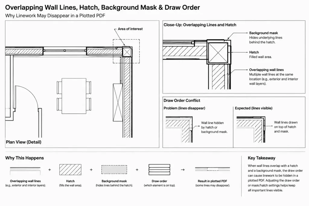
Also verify that geometry has not been hidden by another object. Solid fills, masks, wipeouts, dense hatches, and filled regions can cover lines depending on draw order. If a line exists but vanishes only in a particular area, test draw order before changing its lineweight.
Confirm the Plot Style Workflow
Architectural files may use color-dependent plot styles or named plot styles. The selected table must match the drawing’s intended workflow. A mismatch can produce uniform lineweights, unexpected grayscale values, or colors that remain visible when monochrome output was expected.
When reviewing the plot style setup, ask the following:
- Is the intended plot style table assigned to the layout?
- Is the option to apply plot styles enabled?
- Do object colors correspond to the office plotting convention?
- Are named styles actually assigned where the drawing expects them?
- Has the plot style file been edited or replaced?
Avoid solving a single bad line by changing a shared plot style table unless the table itself is incorrect. A global change can alter every sheet and every object using that plotted property.
Inspect Page Setup and Output Configuration
Compare an affected layout with a layout that plots correctly. Review the selected output device, sheet size, plot area, orientation, scale, plot style table, lineweight settings, transparency behavior, and quality options. Saved page setups reduce variation between sheets, but they can also preserve outdated settings if copied from another file.
If several team members produce different results from the same DWG, compare their page setup resources and plot style files. The drawing may reference a plotting resource that is missing or different on another workstation.
Diagnose Common Symptoms
| Symptom | Likely areas to inspect | Useful test |
|---|---|---|
| One line is missing | Object properties, layer plotting status, draw order, clipping | Copy it to a known plotting layer and preview again |
| An entire category is missing | Layer state, viewport freeze, external reference layers | Compare layer conditions inside the affected viewport |
| Walls plot too heavily | Duplicate geometry, object overrides, plot style mapping | Isolate a wall and check for overlapping lines |
| Text is faint | Text color, plot style screening, transparency, font rendering | Plot a sample note beside known-good text |
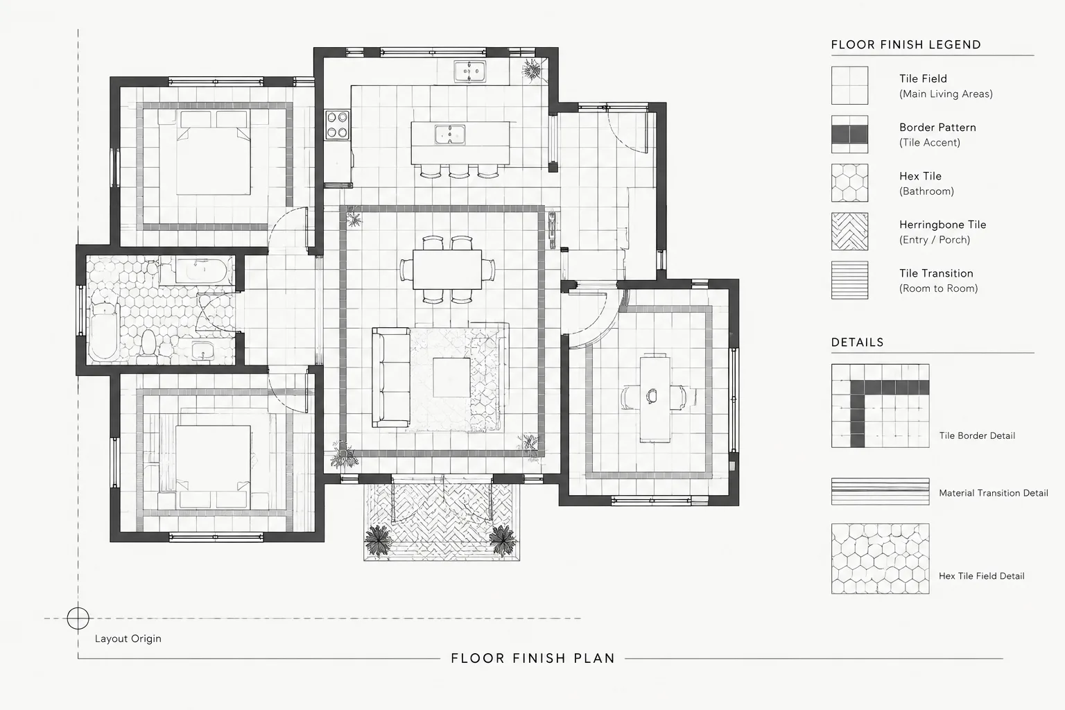
| Hatches become solid or disappear | Pattern density, output quality, clipping, scale, PDF display | Zoom into preview and compare a simplified hatch sample |
| Only one viewport is wrong | Viewport layer overrides, viewport scale, annotation visibility | Compare the viewport properties with a correct view |
| Preview is correct but PDF is wrong | PDF output configuration, file processing, viewer display | Open the PDF in another viewer and inspect at different zoom levels |
Check External References and Nested Content
Missing graphics may originate in an attached file rather than the host drawing. Confirm that the reference is loaded, its layers are set to plot, and its geometry is not clipped unexpectedly. Nested blocks and references can also contain internal color, layer, or lineweight assignments that differ from the host file.
If reference geometry plots incorrectly, open the source file and test it independently. This distinguishes a source-file problem from a host-file display or viewport problem. Avoid exploding references or complex blocks merely to force a plot result; that can make future coordination much harder.
Separate PDF Display Problems from Drawing Problems
Vector linework can appear inconsistent at certain zoom levels because a PDF viewer must translate very thin geometry onto screen pixels. A line that seems absent at a full-sheet view may appear when enlarged. Dense hatch patterns can also produce screen artifacts that are not present in a physical print.
Open the PDF in another viewer, zoom into the affected area, and produce a controlled test print if needed. If the PDF behaves correctly elsewhere, changing the DWG may not be appropriate. The issue may be limited to display smoothing, rendering, or printer processing.
A Reliable Troubleshooting Sequence
-
Identify one specific object or area that demonstrates the problem.
-
Check whether the issue appears in model space, the layout, plot preview, the PDF, or only the physical print.
-
Inspect object properties and compare them with known-good geometry.
-
Review the layer’s plotting status and viewport-specific conditions.
-
Check for masks, fills, overlapping lines, clipping, and draw-order conflicts.
-
Confirm the layout’s plot style table and page setup.
-
Test referenced files and nested block content separately.
-
Open the output in another PDF viewer before changing the drawing globally.
-
Replot a limited test sheet and document the correction.
Preventing Future Plotting Problems
Consistent office templates, controlled plot style files, standardized page setups, and layer-based object properties reduce plotting variation. Include representative walls, thin detail lines, text, dimensions, hatches, grayscale fills, and reference content on a plotting test sheet. This provides a quick visual check whenever templates or output configurations change.
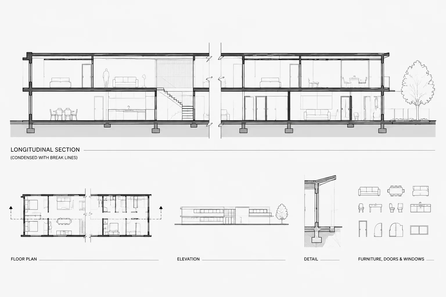
Before issuing a drawing set, review PDFs rather than assuming a successful plot command means the output is correct. Check several sheet types at readable magnification, including plans, elevations, sections, details, and schedules. A disciplined PDF review catches missing information while there is still time to correct its actual source.
Record the Result Before Closing the Issue
After finding the cause, document both the symptom and the correction. A useful note identifies the affected object or sheet, where the problem first became visible, which setting caused it, and whether the correction belongs to the drawing, a shared plotting resource, or the output environment.
This record helps distinguish a one-time drafting error from a repeatable workflow problem. It is particularly valuable when several people publish the same drawing set or when page setups and plot style files are shared across projects.
Use the Failure Boundary to Guide the Fix
- Wrong in the drawing and preview: concentrate on object properties, layers, viewport conditions, references, masks, clipping, and plot style assignments.
- Correct in the drawing but wrong in preview: compare layout configuration, page setup, plotting resources, and the selected output device.
- Correct in preview but wrong in the PDF: test the PDF generation process and inspect the file in another viewer before modifying geometry.
- Correct in the PDF but wrong on paper: investigate the printer, print driver, viewer print settings, and downstream processing.
- Different between workstations: compare referenced resources and output configurations rather than assuming the DWG itself changed.
Validate the Correction Without Creating a New Problem
Recheck representative linework after applying a fix. A change that restores one faint line may unintentionally affect walls, annotations, hatches, external references, or other layouts. Prefer a local correction when the defect is local, and change a shared plot style or template only when testing confirms that the shared resource is the source.
Frequently Asked Questions
Why is a line visible in model space but missing from the PDF?
The line may be on a nonplotting layer, frozen in the layout viewport, hidden by another object, affected by clipping, or mapped to an output appearance that is too faint to distinguish. Check plot preview to determine whether the problem occurs before PDF creation.
Why do walls plot heavier than nearby geometry?
Possible causes include overlapping objects, direct lineweight overrides, block components with internal properties, viewport overrides, or an unexpected plot style mapping. Isolate a sample wall and compare it with known-good geometry before changing the entire plotting setup.
Can a PDF viewer make correct CAD linework appear wrong?
Yes. Thin vector lines and dense patterns can look uneven or disappear at some screen magnifications. Inspect the affected area more closely, open the PDF in another viewer, and compare a controlled print before editing the DWG.
Should a shared plot style be edited to fix one bad object?
Usually not until the plot style has been confirmed as the cause. If only one object is wrong, inspect its layer and direct properties first. Editing a shared plotting resource can change unrelated sheets and drawings.
Why does the same DWG produce different PDFs on different workstations?
The workstations may not be using identical plot style files, page setups, output configurations, fonts, or referenced resources. Compare the complete publishing environment as well as the drawing file.
What should be included in a plotting test sheet?
Include examples of the graphic content used by the drawing set, such as walls, fine linework, text, dimensions, hatches, fills, and referenced geometry. The purpose is to make unexpected plotting changes easy to see before a full set is issued.