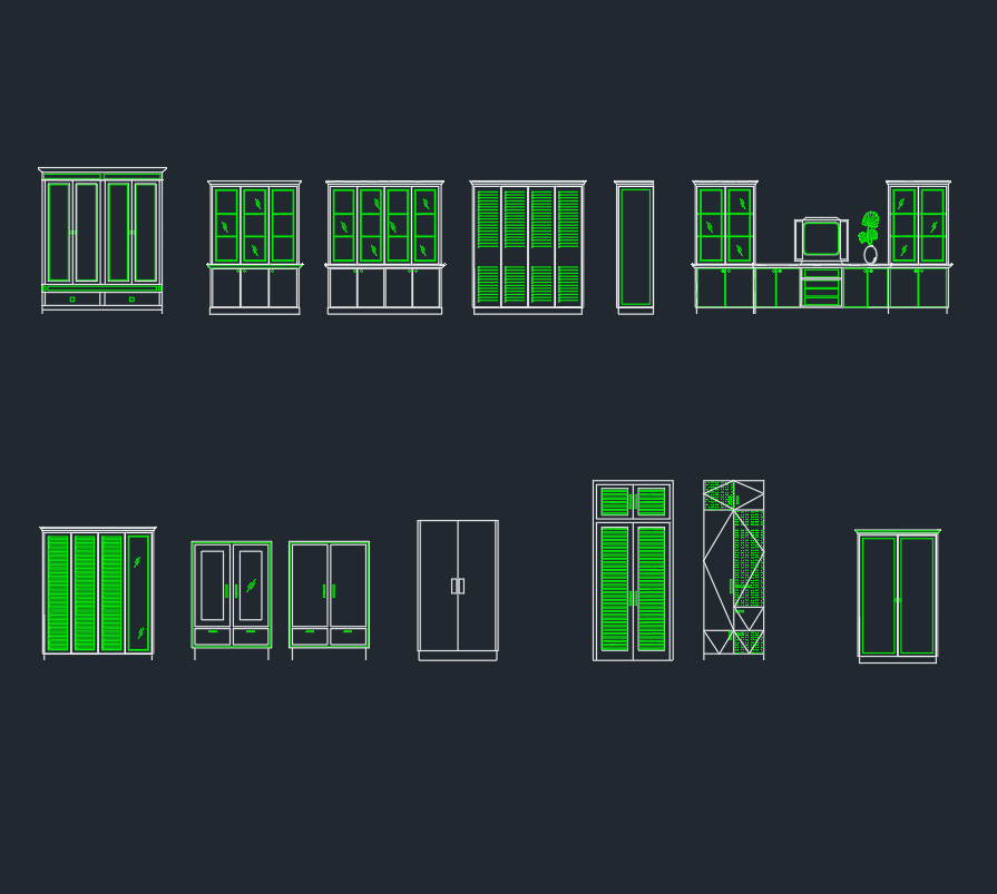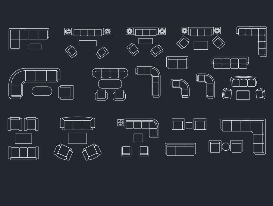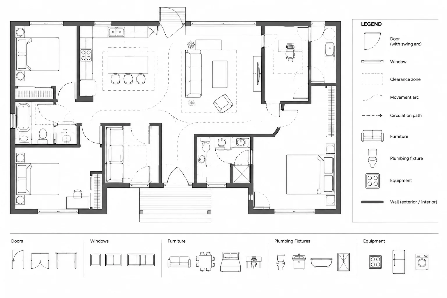
Architectural CAD clearance zones help drafters evaluate how a layout works beyond the visible footprints of walls, fixtures, furniture, doors, and equipment. By showing movement, access, approach, and service space as separate coordination geometry, a plan can reveal conflicts that ordinary object linework may conceal.
This guide explains how to create, organize, review, and document clearance zones without confusing them with constructed elements or treating them as automatic evidence of compliance. Any zone used on a project should reflect verified criteria and remain coordinated as the design develops.
Architectural plans often show where an object is located without showing the space needed to use it. A door leaf may fit within a wall opening, a chair may fit under a table, and a plumbing fixture may fit against a partition, yet the surrounding layout can still create operational or circulation conflicts.
Clearance zones make these hidden spatial requirements visible. They can represent door movement, user activity, equipment access, furniture pull-out space, maintenance access, or another project-specific constraint. When organized correctly, they become useful coordination geometry rather than a collection of distracting dashed lines.
A clearance zone in a CAD file should not be treated as proof of code compliance. Its size, shape, purpose, and location must be checked against the governing requirements, approved project criteria, manufacturer information, and current design conditions. The drafter’s role is to represent verified criteria clearly and keep them coordinated as the plan changes.
Separate the object from the space around it
A useful starting point is to distinguish between physical geometry and operational geometry. The physical geometry represents the item itself, such as a cabinet, appliance, door, toilet, desk, or mechanical unit. Operational geometry represents the space associated with using, opening, approaching, inspecting, or servicing that item.
Common types of operational geometry include:
- Movement zones: Areas occupied by moving components such as doors, drawers, cabinet fronts, folding panels, or movable partitions.
- User zones: Space intended for a person using a fixture, workstation, counter, seat, or piece of equipment.
- Approach zones: Space needed to reach or approach an element from a particular direction.
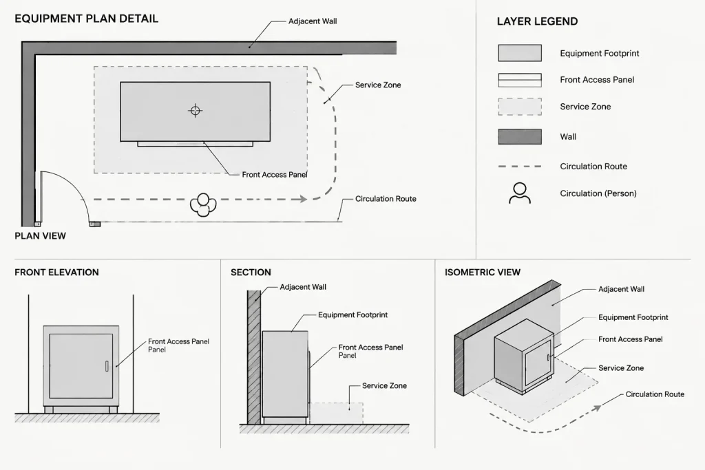
- Service zones: Areas reserved for inspection, repair, replacement, cleaning, or equipment access.
- Circulation zones: Routes through rooms, around furniture, and between architectural elements.
- Temporary operating zones: Space occupied only while an item is in use, such as a pulled-out chair or an open appliance door.
These zones can overlap legitimately, but each overlap should be intentional. A maintenance area that crosses a movable chair zone may be acceptable under the project criteria, while a required access route blocked by fixed casework may indicate a real design conflict.
Confirm the source of each clearance
Do not begin by copying a dashed rectangle from an unrelated detail or downloaded block. First identify why the clearance exists and where its criteria came from. Possible sources include project design standards, consultant requirements, verified product information, owner operational requirements, and applicable regulations.
Add enough information to the working file to preserve that intent. A short note such as “equipment service zone,” “door operation,” or “movable furniture position” is more useful than an unexplained outline. If the dimensions remain under review, label the zone accordingly rather than presenting it as finalized.
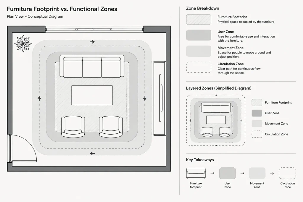
Downloaded CAD blocks require particular care. A block may include a clearance outline, but that outline could represent a generic recommendation, a different product, or an unknown drafting convention. Retain it only after confirming its meaning and suitability for the current project.
Use a deliberate layer strategy
Clearance geometry should be easy to display during coordination and easy to control on issued drawings. Avoid placing it on the same layer as the physical object. Separate layers allow the project team to distinguish permanent construction from analytical or operational information.
| Geometry category | Typical CAD treatment | Coordination purpose |
|---|---|---|
| Physical object | Normal object layer and project linework hierarchy | Shows the installed or constructed item |
| Door or panel movement | Dedicated movement or swing layer | Reveals conflicts with walls, fixtures, and furniture |
| User or approach area | Light boundary, optional hatch, and brief label | Communicates space associated with use |
| Equipment service area | Distinct service-clearance layer | Supports consultant and manufacturer coordination |
| Circulation study | Working or analysis layer | Tests routes without changing construction geometry |
| Unverified zone | Clearly identified review layer | Prevents preliminary information from appearing final |
Layer names should follow the office or project CAD standard. The important principle is functional separation. Color alone is not enough because drawings may be printed in monochrome, viewed with altered display settings, or transferred into another file environment.
Build reusable clearance blocks carefully
Repeated items can benefit from blocks that include both physical and clearance geometry. Examples may include desks with chair-use zones, appliances with open-door positions, fixtures with approach areas, or equipment with service boundaries.
Keep the block structure understandable. Use separate internal layers for the object and its clearance components so the graphic can be controlled without exploding the block. Choose an insertion point tied to a stable installation reference, such as a wall face, centerline, corner, or connection point. Avoid insertion points based on the outer edge of a clearance zone because that edge may change when the criteria are updated.
Use descriptive block names that identify the object and, where necessary, the type of operational information included. A generic name such as “rectangle” makes later auditing difficult. Block descriptions or adjacent notes can clarify whether a zone represents operation, access, service, or preliminary planning.
If different configurations have genuinely different clearance conditions, do not force them into one ambiguous symbol. Separate, clearly named blocks are often easier to review than a complicated block whose current state is not obvious.
A practical drafting workflow
1. Stabilize the architectural base
Begin with coordinated walls, openings, columns, fixed casework, and major fixtures. Clearance studies performed on an outdated background produce false conflicts and missed conflicts. If the plan uses external references, confirm that the references are current and correctly positioned before reviewing space around objects.
2. Place the physical objects first
Locate doors, furniture, fixtures, and equipment according to the design. Check their insertion points, orientation, scale, and relationship to nearby construction. A clearance zone cannot correct an incorrectly placed block.
3. Add verified operational geometry
Draw or display the relevant movement, approach, user, and service zones. Use closed polylines where a continuous boundary is needed. Keep arcs and swing graphics connected to the object they describe. Apply hatches sparingly; dense patterns can hide dimensions and make small rooms difficult to read.
4. Review interactions, not just isolated objects
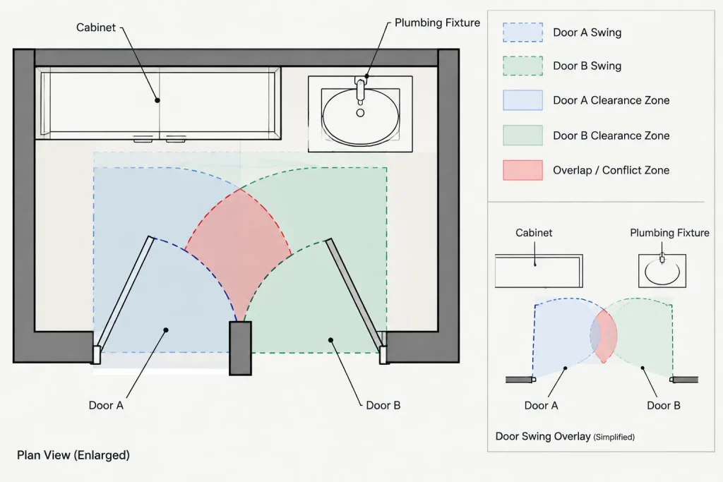
Look for overlaps between clearance zones and walls, door swings, columns, plumbing fixtures, counters, loose furniture, and adjacent equipment. Also review overlapping operational zones. The object footprints may not touch even when their use zones create a conflict.
5. Resolve the layout at the appropriate level
A conflict may require moving an object, changing a door operation, revising casework, selecting different equipment, or requesting clarification from another discipline. Do not quietly reshape a verified clearance boundary merely to make the plan appear coordinated.
6. Record unresolved items
Place uncertain zones on a review layer and add a concise note or issue marker. Maintain a clear distinction between verified criteria and assumptions. This helps reviewers focus on decisions that are still needed.
7. Recheck after design changes
Clearances should be reviewed whenever walls, doors, furniture, fixtures, or equipment move. They should also be checked after an external reference is updated. A clean plan is not necessarily a coordinated plan if its operational geometry was not updated with the design.
Pay special attention to door interactions
Doors create some of the most common clearance conflicts because several conditions meet at one opening. The plan may need to account for the leaf swing, hardware side, wall returns, nearby fixtures, furniture, and the approach to the opening. Sliding and folding systems have different operating geometry from hinged doors and should not be represented with a generic swing symbol.
Review doors from both connected spaces. A door that appears clear inside one room may interfere with corridor circulation or another door on the opposite side. In small rooms, compare the open leaf with fixture-use zones and cabinet operation. In shared circulation areas, examine clusters of doors together rather than one at a time.
The door swing itself is not a substitute for any separately required approach or maneuvering area. Show each type of information according to its purpose, using verified project criteria.
Coordinate furniture and equipment as operating layouts
Furniture plans are more useful when they show how spaces function, not merely how many objects fit. Test chairs in both stored and occupied positions where relevant. Review drawers, cabinet doors, appliance doors, and movable panels in their operating positions. Check whether a person can reach an item without crossing another critical zone.
Equipment coordination should also consider service access. The architectural footprint received from a consultant may show only the equipment enclosure. Ask whether access panels, replacement paths, connections, or working areas need to be represented. Keep architectural service zones distinct from consultant geometry so responsibility remains clear.
Control what appears on issued drawings
Not every working clearance must appear on every sheet. A circulation study may be useful during design but unnecessary on a construction floor plan. Conversely, an equipment service zone may need to remain visible on a coordination or enlarged plan.
Decide sheet by sheet whether clearance information should be plotted, screened, labeled, or hidden. Test the actual plotted result. Boundaries that look subtle on screen can become dominant in print, while very light graphics may disappear completely.
When a clearance is critical to interpreting the drawing, do not rely on line type alone. Add a direct label, keyed note, or legend entry. Keep the explanation near the relevant plan when practical so readers do not have to guess what a dashed outline means.
Clearance-zone quality-control checklist
- Is the purpose of every clearance boundary identifiable?
- Does each zone come from a verified project source rather than an arbitrary block?
- Are physical objects and operational zones on separate layers?
- Are blocks inserted at the correct location, orientation, and drawing scale?
- Have door swings been reviewed with nearby fixtures, furniture, and other doors?
- Have movable components been checked in their operating positions?
- Are equipment service areas coordinated with current consultant information?
- Are unresolved or preliminary zones clearly distinguished from verified criteria?
- Were clearances rechecked after background and external-reference updates?
- Is the plotted graphic clear without overwhelming the architectural plan?
Treat clearances as live coordination information
Architectural CAD clearance zones are most valuable when they remain connected to design intent. They should identify the space needed around an object, expose conflicts early, and communicate which criteria still require confirmation. They should not become decorative dashed outlines or unsupported claims of compliance.
By separating physical and operational geometry, using controlled layers, documenting sources, and reviewing interactions after every significant plan change, CAD users can produce layouts that are easier to understand and more useful to the entire project team.
Make each clearance traceable during review
A clearance boundary is more useful when another team member can determine what it represents, which object it belongs to, and whether its criteria have been confirmed. Layer names, block descriptions, nearby notes, and issue markers can provide that context without crowding the plan.
During a review, distinguish between a geometric conflict and a criteria question. A geometric conflict is visible when a verified zone intersects an incompatible object or operating area. A criteria question exists when the team has not yet confirmed the boundary, operating condition, product information, or project requirement. The first may require a layout revision; the second requires clarification before the drawing can support a reliable decision.
Review ownership as well as geometry
Clearance information may originate with the architect, an interior designer, a consultant, an equipment supplier, an owner, or another project participant. The CAD file should make these sources understandable without implying that the drafter independently established the requirement.
- Confirm the associated object: Make sure the zone moves with the correct door, fixture, furniture block, or equipment item.
- Confirm the operating condition: Identify whether the outline represents normal use, temporary movement, approach, inspection, or service.
- Confirm the review status: Separate verified information from placeholders and assumptions.
- Confirm drawing visibility: Decide whether the zone belongs only in the working file or should appear on a plotted coordination document.
- Confirm change management: Revisit the zone when its object, surrounding construction, product selection, or referenced background changes.
Use conflicts to improve the plan, not the graphic
When a clearance zone exposes a problem, revise the underlying layout or request the information needed to resolve it. Trimming, stretching, or hiding a verified boundary solely to remove an overlap defeats its coordination purpose. If a temporary graphic adjustment is necessary for investigation, keep it clearly identified as a study rather than approved project information.
A well-managed clearance system supports design discussions because it shows both the physical arrangement and the operational consequences of that arrangement. Its value comes from accurate intent, disciplined layer control, and repeated review—not from the dashed boundary alone.
Frequently asked questions
What is a clearance zone in an architectural CAD plan?
It is graphical information representing space associated with movement, use, approach, circulation, inspection, or service around an object. It is separate from the physical footprint of the object itself.
Should clearance zones be included inside CAD blocks?
They may be included when the operational geometry belongs consistently to the blocked object. The physical and clearance components should remain separately controllable, and the meaning and source of the clearance should be documented.
Should a clearance boundary be placed on the object layer?
Normally, functional separation is more useful. A dedicated layer allows the team to display, review, plot, or hide operational geometry without changing the representation of the physical object.
Does a clearance zone prove that a plan complies with applicable requirements?
No. It is a coordination graphic, not proof of compliance. Its criteria must be checked against the governing requirements, approved project information, current product data, and actual design conditions.
What should happen when two clearance zones overlap?
Review what each zone represents before treating the overlap as a conflict. Some operating areas may overlap acceptably under the project criteria, while other overlaps may prevent access, movement, or service. The decision should be based on verified intent rather than appearance alone.
How should an unverified clearance be shown?
Place it on a clearly identified review layer and label it as preliminary or requiring confirmation. This prevents an assumption from being mistaken for finalized project information.
When should clearance zones be checked again?
Recheck them after relevant changes to walls, openings, doors, casework, furniture, fixtures, equipment, product selections, or referenced backgrounds. The zone should remain coordinated with both its object and the surrounding plan.