Drafting site boundaries requires more than selecting a linetype and tracing a base drawing. Property lines, easements, setbacks, rights-of-way, and other limits describe different conditions, come from different sources, and affect design coordination in different ways.
This guide explains how to organize that information in architectural CAD while protecting the integrity of survey geometry. It covers source-file review, layer separation, graphic hierarchy, setback construction, annotation, revision control, and coordination with proposed site work.
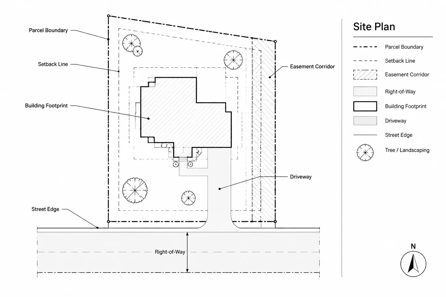
Property lines, easements, setbacks, and similar site boundaries can look deceptively simple in a CAD drawing. Each may appear as little more than a linetype and a label, yet they represent different information and should not be treated interchangeably. Confusing them can distort the site plan, obscure design constraints, and create coordination problems across the drawing set.
A reliable workflow begins with verified source information, not with tracing whichever line is easiest to see. The drafter must preserve the distinction between surveyed boundaries, recorded rights, regulatory limits, and project-specific design controls. The architectural drawing should communicate these conditions clearly without implying legal or regulatory certainty that the source documents do not support.
Understand What Each Boundary Represents
Before assigning layers or linetypes, identify the meaning of each line. Similar-looking boundaries may come from entirely different sources and may have different implications for the design.
Property lines
A property line describes the boundary of a parcel or legal lot. Architectural teams usually receive this information from a survey, civil drawing, or other project document prepared by a qualified source. Property lines should not be reconstructed from fences, paving edges, aerial imagery, neighboring walls, or informal sketches.
A physical feature may follow a property line, but its visible location does not prove the legal boundary. Keep surveyed boundary information distinct from site features even when they overlap graphically.
Easements
An easement identifies an area associated with a particular right or restriction. It may relate to access, utilities, drainage, maintenance, or another recorded purpose. An easement is not automatically a property line and should not be drafted as one.
The architectural site plan should identify the easement by its documented description when that information is available. Avoid replacing a specific easement label with a vague note such as “restricted area,” because the generic wording removes useful context.
Setbacks and required yards
A setback is generally a regulatory or project-defined limit that affects where construction may occur. Its location may depend on the applicable zoning interpretation, street frontage, lot configuration, measured reference, or proposed use. For that reason, a setback should not be created by casually offsetting every property line by the same distance.
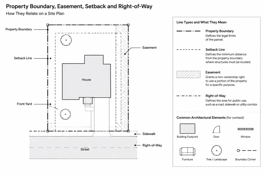
Use the verified planning or zoning information provided for the project. If a value or measurement basis remains unresolved, flag it for confirmation rather than presenting a provisional line as final.
Other site limits
A site plan may also include rights-of-way, building restriction lines, flood-related limits, environmental boundaries, utility corridors, landscape buffers, construction limits, or jurisdictional boundaries. These should receive distinct names and graphics when they represent different conditions.
Start with Authoritative Source Files
Architectural drafting should preserve the information supplied by the responsible discipline. A survey or civil base is normally more reliable than a previously exported architectural background, a scanned exhibit, or a conceptual plan.
Before drafting, review the available source material for:
- Parcel corners and boundary segments
- Bearings, distances, curves, and recorded references
- Easement labels and purposes
- Rights-of-way and adjoining streets
- Existing monuments or survey points
- Notes describing the basis of the survey
- Coordinate, unit, and orientation information
- Items marked approximate, record-based, or field-located
Do not silently “correct” a source because a line looks slightly misaligned with an architectural wall or imported image. Investigate the discrepancy. The building geometry, image scaling, project coordinates, or source translation may be the actual problem.
Keep the Survey Base Separate
A practical CAD workflow keeps the consultant or survey base separate from architectural design geometry. Referencing the source file allows the team to display it while reducing the risk of editing authoritative linework unintentionally.
If project requirements call for copied geometry, retain a clearly identified source file and record where the copied information came from. Avoid exploding, trimming, stretching, or redrawing survey geometry merely to make the site plan look cleaner. Graphic cleanup should not change the underlying boundary.
Create a Clear Layer Structure
Property lines, easements, setbacks, rights-of-way, and annotation should not all share one generic site layer. Separate layers make it easier to control plotting, isolate information, compare revisions, and build different site-plan views.
| Information type | Recommended CAD separation | Coordination purpose |
|---|---|---|
| Property boundary | Dedicated boundary layer | Preserves the legal parcel outline |
| Easement limits | Separate layer by category when useful | Distinguishes recorded rights from ownership boundaries |
| Setback lines | Dedicated regulatory or planning layer | Allows design constraints to be reviewed independently |
| Right-of-way | Separate right-of-way layer | Prevents confusion with curb and pavement edges |
| Boundary labels | Annotation layer | Supports view-specific text control |
| Bearings and distances | Dimension or survey annotation layer | Keeps technical boundary data distinct from general notes |
Use the project layer standard where one exists. The exact layer names are less important than consistent separation and clear documentation.
Build a Deliberate Graphic Hierarchy
Each boundary should remain visible without competing with the proposed building. Assign linetypes and lineweights according to meaning rather than visual preference alone.
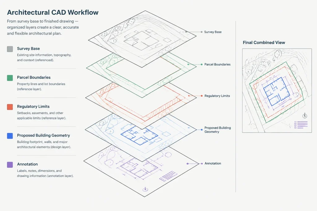
A property line often needs to read as a primary site reference. Easements and setbacks should be recognizable but may be graphically secondary. Existing utilities, topography, planting, and paving should not obscure these limits.
Check the plotted sheet rather than relying only on the model-space display. Closely spaced linetypes can merge at the intended sheet scale, especially where several limits follow the same alignment. Adjust the drawing presentation without moving the actual geometry.
Handle coincident lines carefully
When a setback, easement, or right-of-way shares part of another boundary, stacking several linetypes may create an unreadable result. Possible presentation methods include:
- Using a leader to identify the coincident conditions
- Adding a concise note that names both boundaries
- Providing a small enlarged site-plan view
- Using separate diagrams for different approval or coordination purposes
- Temporarily controlling selected layers in a specific viewport
Do not move a boundary away from its documented position simply to separate the graphics unless the displacement is explicitly presented as a diagrammatic convention.
Draft Setbacks from the Correct Reference
An offset command can create geometry efficiently, but it does not determine what the setback should be measured from. The controlling reference might be a property line, street line, right-of-way, designated frontage, or another defined limit. Curved and irregular parcels require particular care.
Before constructing a setback line:
- Confirm the applicable source and measurement basis.
- Identify which parcel edge serves each side or frontage condition.
- Check how corners, curves, and unusual lot shapes are addressed.
- Determine whether separate limits apply to different site elements.
- Label unresolved information as pending rather than assumed.
Keep calculated setback geometry separate from imported survey geometry. This distinction makes it easier to update the regulatory information without affecting the parcel boundary.
Use Labels That Explain the Line
A linetype alone is rarely enough. Readers may view a grayscale print, a reduced sheet, or a partial plan without access to the CAD layer names. Apply direct labels where practical and support them with a legend when several boundary types appear.
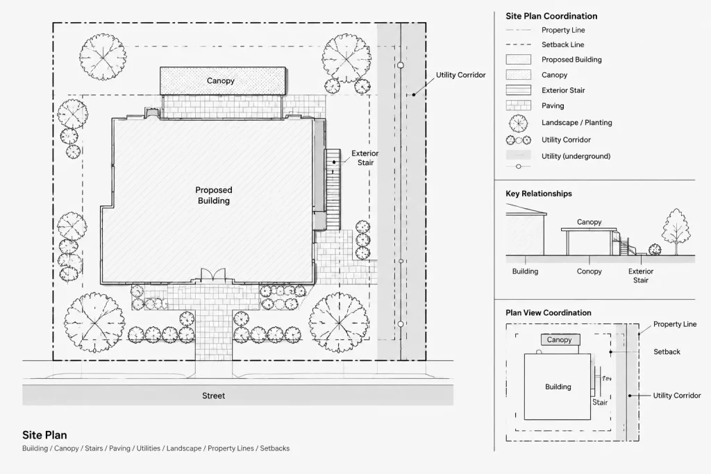
Useful labels identify the actual condition, such as the property boundary, a particular easement purpose, or the applicable setback category. Place text so that it cannot be mistaken for a dimension or a label belonging to a nearby line.
If bearings and distances are shown, orient and position them consistently. Preserve the source notation instead of retyping it from memory. Where architectural presentation requirements differ from the survey exhibit, retain traceability to the original information.
Coordinate the Proposed Design Against Site Limits
Boundary drafting becomes useful when it supports design review. Compare the proposed building, canopies, stairs, ramps, walls, equipment, paving, parking, drainage features, and landscape elements with the relevant limits. Do not assume that checking the main exterior wall is sufficient.
Use a repeatable review process:
- Isolate the proposed work and controlling site limits.
- Inspect narrow gaps and near-coincident geometry at corners.
- Check roof projections and overhead elements separately from the footprint.
- Review below-grade and site-mounted components where applicable.
- Compare the architectural plan with current civil and landscape files.
- Record unresolved conflicts instead of hiding them graphically.
A clearance shown in CAD is only as reliable as the source geometry and interpretation behind it. It should not be described as compliant until the responsible project team has verified the applicable requirements.
Manage Revisions Without Losing Traceability
Survey and entitlement information may change during a project. A revised parcel boundary, easement, or right-of-way can affect the entire design. Date and identify incoming source files, then compare them with the previous issue before replacing the project background.
After an update, review more than the visible linework. Recheck setback construction, dimensions, labels, area calculations, building placement, parking, access, and associated details. Remove superseded geometry or archive it outside the active plotting layers so that old and new limits cannot be confused.
Final CAD Review Checklist
- Property lines come from an identified, reliable source.
- Easements are not represented as parcel boundaries.
- Setbacks use the verified reference and interpretation.
- Survey geometry remains separate from architectural construction lines.
- Boundary categories use distinct layers and readable graphics.
- Coincident lines are explained without falsifying their locations.
- Labels remain legible at the intended sheet scale.
- Proposed work has been compared with all relevant site limits.
- Revised source information has been coordinated across affected drawings.
- Unverified conditions are clearly flagged for confirmation.
A well-drafted site plan does more than display a parcel outline. It establishes a dependable relationship between source documents, regulatory constraints, and proposed design geometry. By separating each boundary type, preserving source integrity, and documenting uncertainty, the CAD drawing becomes easier to review and safer to coordinate.
Applying This Workflow to a Project
Use the completed site plan as a coordination drawing rather than as a substitute for the survey, recorded documents, or planning interpretation. Every important boundary should remain traceable to its source, and every constructed limit should be distinguishable from imported geometry.
When several disciplines share the site base, establish responsibility for updating boundary information and communicating revisions. Architectural, civil, landscape, and other project files should be compared after a source change so that obsolete limits do not remain visible in dependent drawings.
Separate accuracy from presentation
Lineweight, linetype, labels, leaders, and viewport controls may be adjusted to improve readability. The documented location of a boundary should not be changed for graphic convenience. If overlapping conditions require diagrammatic displacement, identify that treatment clearly so readers do not interpret the shifted graphic as surveyed geometry.
Document uncertainty instead of concealing it
Incomplete or conflicting information should remain visible to the project team through a clear note, coordination item, or pending designation. A clean-looking plan is not reliable if unresolved assumptions have been presented as confirmed limits.
Frequently Asked Questions
Can a fence or wall be used to establish a property line?
No. A fence, wall, curb, planting edge, or other visible feature may be near a parcel boundary, but its location does not establish the legal property line. Use boundary information from an identified survey, civil base, or other qualified project source.
Is an easement part of the property boundary?
An easement may cross, follow, or terminate at a property boundary, but it represents a right or restriction rather than parcel ownership geometry. Keep easement limits and property lines on distinct CAD layers and label each condition clearly.
Can setbacks be created by offsetting every property line?
Not automatically. The controlling reference and interpretation may vary with frontage, parcel geometry, planning requirements, or the element being reviewed. Confirm the applicable source before constructing setback geometry.
Should survey linework be copied into the architectural file?
Referencing the survey base generally makes source control and updates easier. If geometry must be copied, preserve an identified source file, document its origin, and keep copied boundary information separate from architectural construction lines.
How should coincident boundaries be shown?
Use labels, leaders, notes, enlarged views, or view-specific layer controls to identify overlapping conditions. Do not shift an actual boundary merely to separate linetypes unless the displacement is clearly presented as diagrammatic.
What should be checked after receiving a revised survey?
Compare the revised source with the previous issue, then review dependent setbacks, dimensions, labels, building placement, site features, access, parking, and related drawings. Superseded geometry should not remain on active plotting layers.