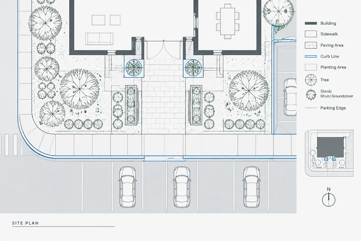
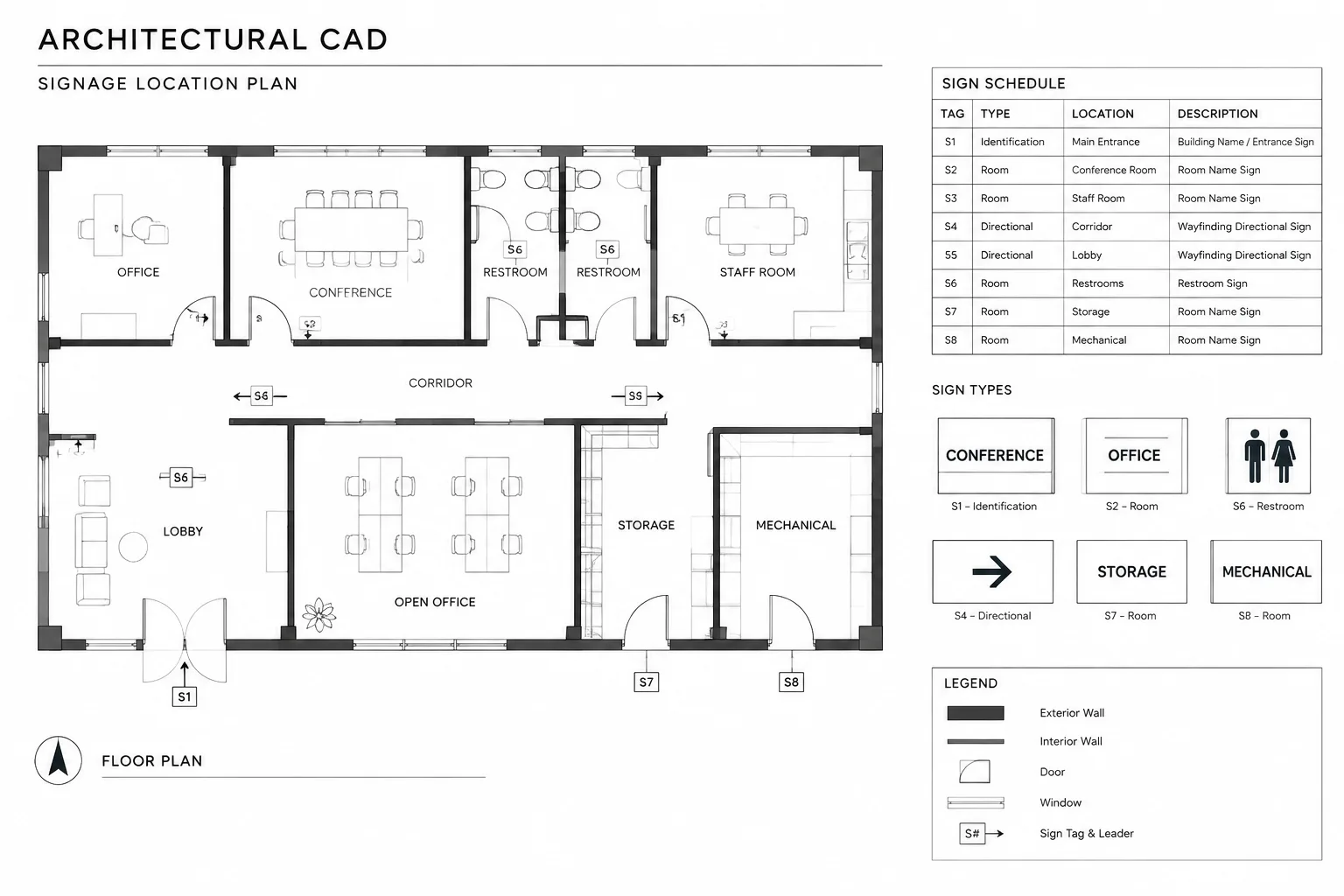
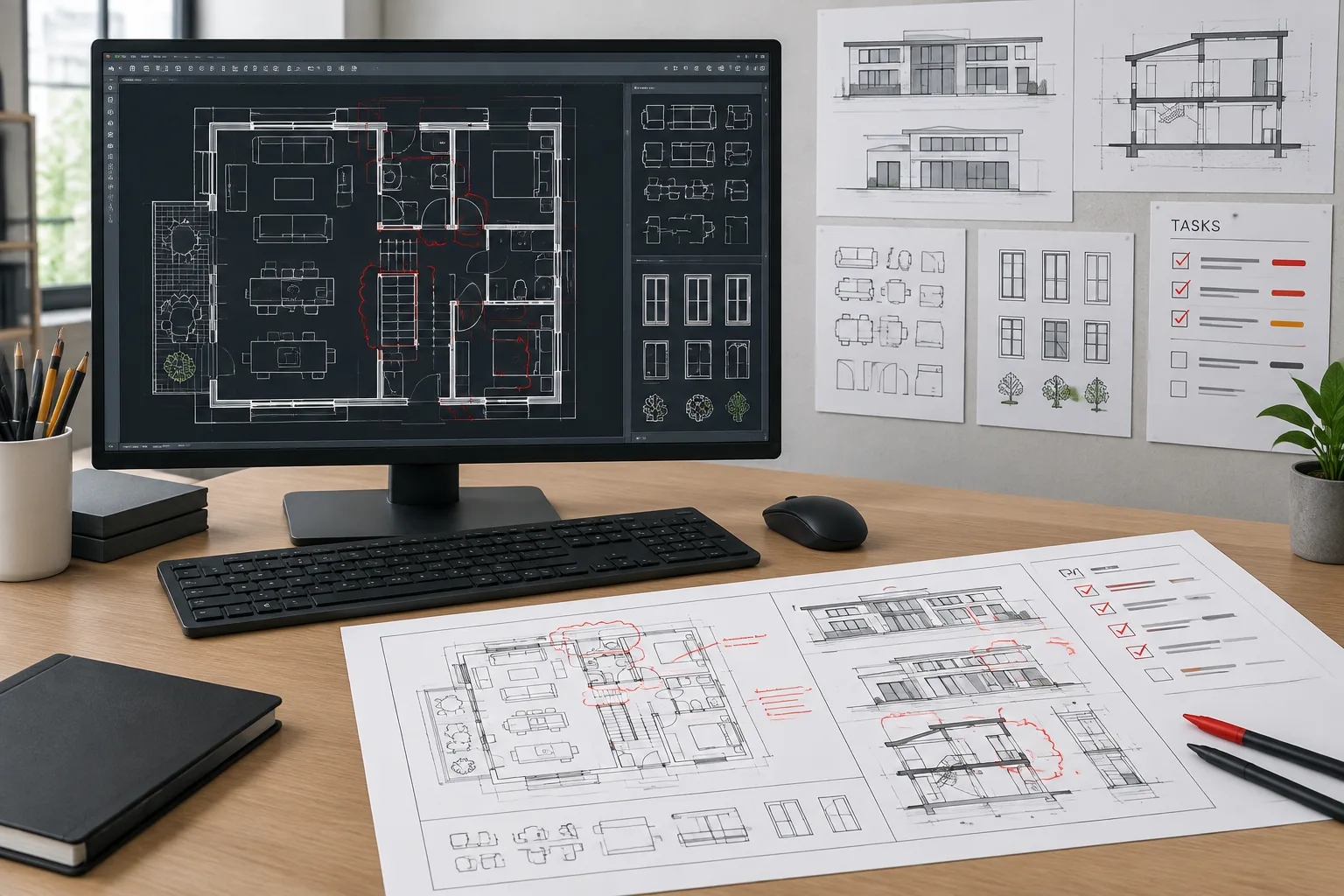
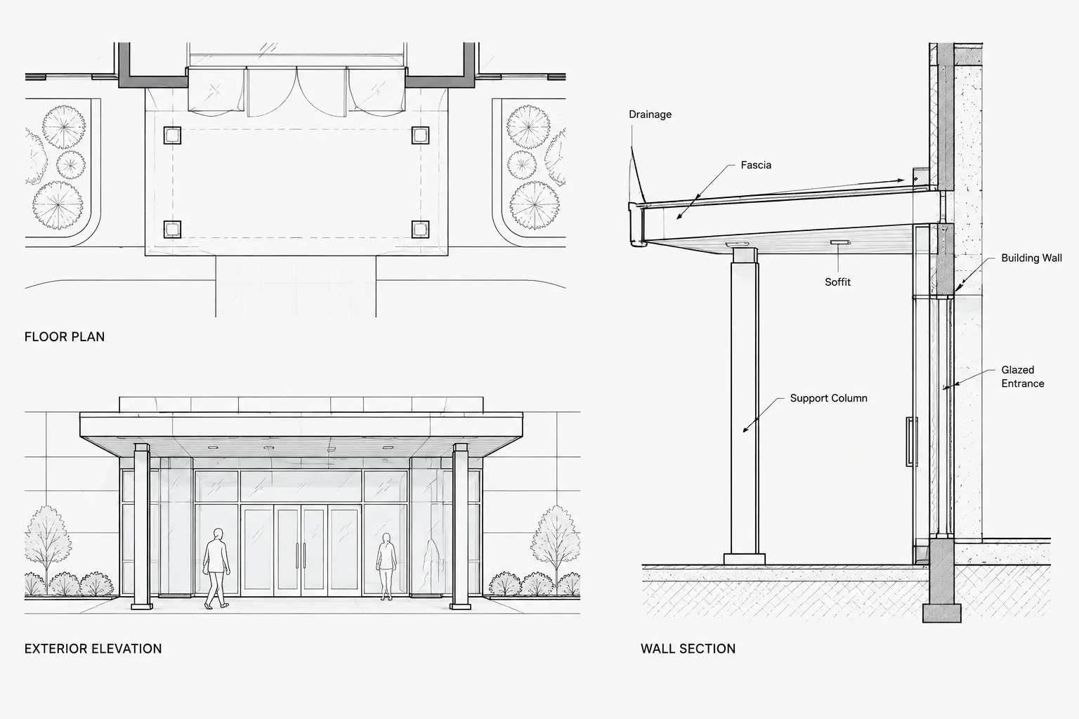
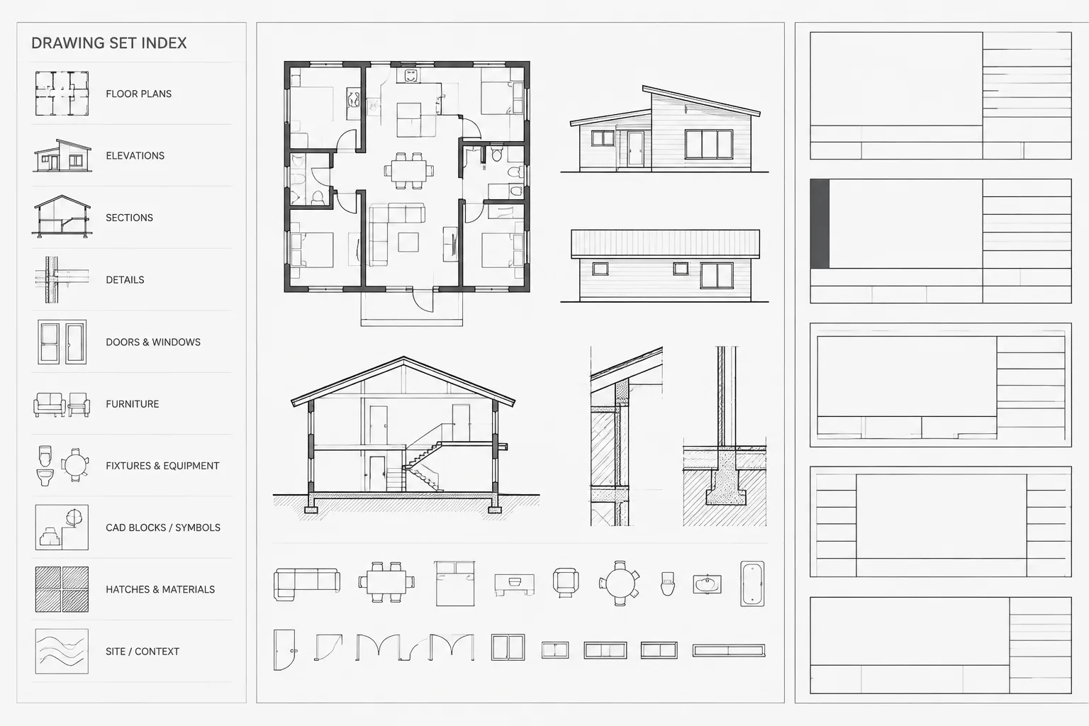
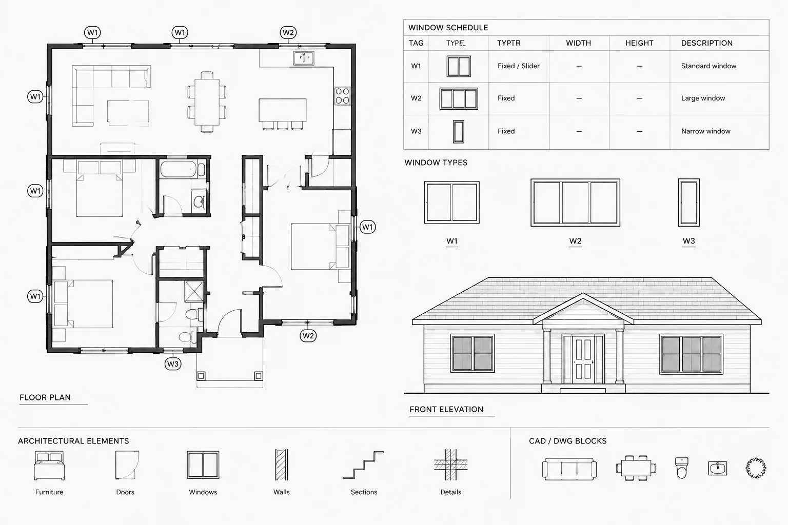
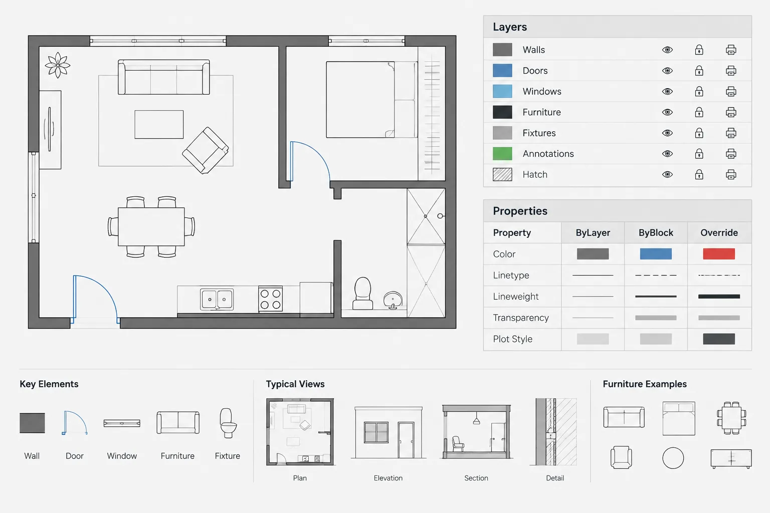
To draft existing conditions in AutoCAD, the drafter must convert field observations into coordinated geometry without concealing uncertainty. The central task is not merely data entry. It is deciding which measurements control the plan, which records provide supporting evidence, and which locations still require verification.
The following guide presents a field-to-CAD workflow built around dependable baselines, common control points, drawing organization, discrepancy management, and quality review. It also explains why measured drawings should distinguish observed conditions from information inferred through photographs, legacy plans, or inaccessible construction.
Drafting an existing building is not simply a matter of transferring handwritten dimensions into AutoCAD. Field information is often incomplete, redundant, or slightly inconsistent. Walls may not be square, finishes may conceal structural geometry, and some areas may be inaccessible. A dependable existing-conditions drawing must communicate both the observed building and the limits of the available information.
This workflow explains how to organize field records, establish reliable reference geometry, resolve measurement conflicts, and produce a clean CAD base for renovation planning. It is suitable for measured floor plans, tenant improvement backgrounds, residential alterations, and other projects where existing documentation must be recreated or verified.
Understand What the Existing-Conditions Drawing Represents
An existing-conditions plan is a record of visible or verified conditions at a particular time. It should not imply that concealed construction, property boundaries, structural capacity, or code compliance has been confirmed unless those items were separately investigated by qualified parties.
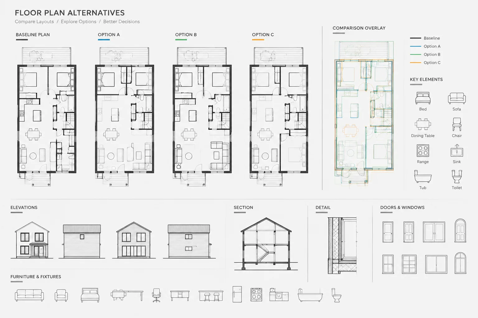
Before drafting, define the intended scope. A basic space-planning survey may focus on wall faces, openings, fixtures, and major equipment. A more detailed renovation survey may also require ceiling changes, floor transitions, soffits, casework, columns, plumbing locations, and exterior features. The required drawing scale and project purpose should determine the level of detail collected.
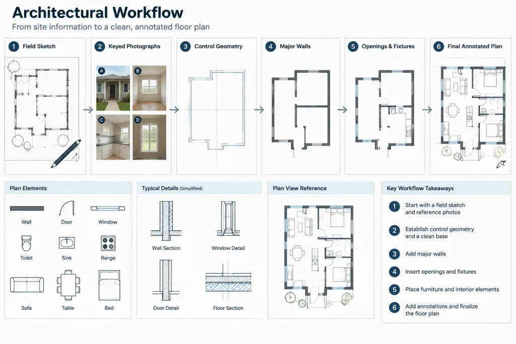
Organize the Field Information Before Drawing
Do not begin by tracing every mark from the field sketch. First, assemble the source material and identify how its parts relate to one another. Common records include:
- Hand sketches with dimension strings and room names
- Overall and partial measurements
- Diagonal measurements used to check squareness
- Door and window locations
- Photographs keyed to rooms or sketch locations
- Notes describing wall thicknesses, steps, slopes, or inaccessible areas
- Previous plans that may be used as references but still require verification
Numbering rooms, sketches, and photographs helps prevent confusion later. A photograph named only by its capture time is difficult to coordinate; a photograph associated with a room and viewing direction is much more useful.
Mark each measurement according to its meaning. Distinguish face-to-face dimensions from centerline dimensions, opening widths from frame widths, and clear room dimensions from overall building dimensions. Many drafting errors begin when two measurements appear similar but reference different physical points.
Set Up a Controlled CAD File
Confirm the drawing units before entering geometry. Then establish layers appropriate to the survey and office workflow. Existing walls, openings, fixtures, overhead elements, text, dimensions, reference images, and verification notes should not all be drawn on one layer.
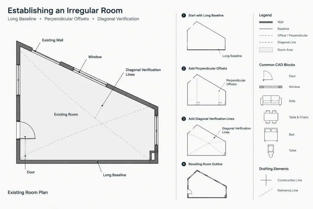
It is useful to separate permanent drawing content from temporary construction geometry. Reference lines, measured points, circles used for triangulation, and discrepancy notes may be placed on dedicated working layers. These layers can remain available for checking without appearing in the issued plan.
If an older drawing is available, attach it as a reference rather than immediately treating it as accurate geometry. Scale and align it only from dimensions or control points that have been independently verified. An old plan can help explain the building, but it should not override current field observations without investigation.
Choose a Reliable Starting Baseline
Begin with the longest dependable dimension or a clearly identifiable building line. This might be an exterior wall face, a corridor wall, or another continuous feature that was measured from stable endpoints. Avoid starting with a small room and expanding outward through a chain of partial dimensions. Small discrepancies can accumulate and distort the overall plan.
Draw the primary baseline and locate major perpendicular or intersecting walls from it. Where the building is not square, do not force the geometry into right angles simply because orthogonal drawing is easier. Use diagonal checks, measured offsets, or multiple control points to establish the actual relationship.
Use a hierarchy of measurement confidence
Not every field dimension deserves equal authority. A practical hierarchy may be organized as follows:
| Measurement type | Typical use in drafting | Coordination concern |
|---|---|---|
| Overall building or room dimensions | Controls the main extent of geometry | Confirm endpoints and whether finishes are included |
| Baseline offsets | Locates walls, openings, and fixed objects | Keep all offsets referenced to the same origin |
| Diagonal checks | Tests angles and room shape | Verify which corners or points were measured |
| Chained partial dimensions | Locates intermediate features | Small errors may accumulate across the chain |
| Visual estimates | Provides provisional context | Identify clearly as unverified |
Build the Plan from Large Geometry to Small Geometry
Draft the overall enclosure and major organizing walls before adding doors, fixtures, or trim. This sequence provides a stable framework for checking whether partial dimensions reconcile with the larger measured shape.
A useful drafting order is:
- Primary exterior or perimeter lines
- Major interior walls and corridor alignments
- Columns, shafts, stairs, and other fixed organizing elements
- Door and window openings
- Casework, plumbing fixtures, and fixed equipment
- Overhead features, floor changes, and other secondary information
- Room names, notes, dimensions, and verification markers
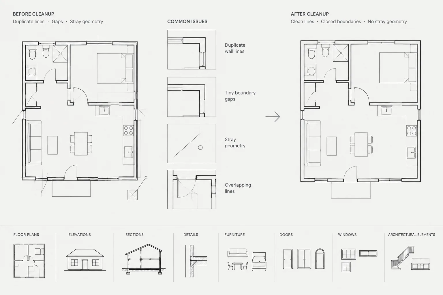
Use polylines, offsets, temporary construction lines, and object snaps carefully. Repeated offsets can be efficient for walls, but they should not be used blindly where wall thickness changes or where measured faces are irregular. Clean intersections as the plan develops so that overlapping or disconnected linework does not conceal coordination problems.
Locate Features from Common Control Points
Whenever possible, locate multiple features from one established baseline rather than dimensioning sequentially from feature to feature. For example, several openings along a wall can be placed from the same wall corner or control line. This reduces cumulative error and makes later checking easier.
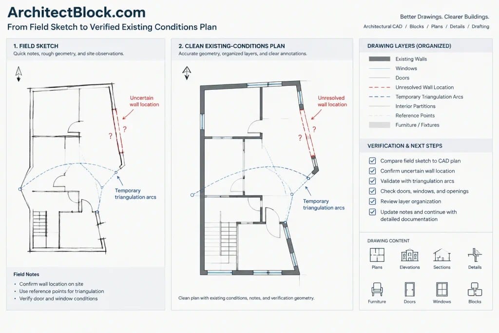
For irregular rooms, triangulation can help locate a corner or object from two known points. In CAD, temporary circles or arcs can represent the measured distances from those points; their intersection provides a candidate location. Keep this construction geometry until the result has been checked against other measurements.
Columns and other isolated objects should be tied to stable references in more than one direction. A single measurement may establish distance from a wall but leave the position along that wall unresolved.
Do Not Hide Measurement Conflicts
Field dimensions frequently fail to close perfectly. The wrong response is to distribute the discrepancy invisibly until the drawing looks neat. First determine whether the conflict comes from different reference faces, an incorrectly transcribed value, an obstructed measurement, or genuinely irregular construction.
Compare the conflicting information with photographs, diagonal checks, and adjacent spaces. If one value is clearly less reliable, retain the stronger control geometry and flag the uncertain location for verification. If the discrepancy affects design decisions, return to the site or request additional information rather than guessing.
Temporary CAD notes can classify unresolved areas, such as:
- Field verification required
- Location based on photograph
- Area inaccessible during survey
- Concealed construction not verified
- Existing drawing used as provisional reference
These notes should be managed intentionally. Some may remain as project notes, while others are internal coordination items that must be resolved or removed before issue.
Represent Existing Conditions Without Overdrawing
The plan should include enough information for its intended use, but unnecessary detail can suggest a level of certainty that the survey does not support. Minor surface irregularities may not need to be traced unless they affect fit, clearance, detailing, or construction scope.
Use consistent conventions for objects above or below the plan cut, concealed items, and features observed only indirectly. Do not draw an assumed wall assembly merely because the wall has a measured overall thickness. Where construction is unknown, show the verified visible geometry and identify the limitation appropriately.
Downloaded blocks for fixtures or furniture can help communicate use, but they should not replace measured extents. Clean and scale any inserted block, confirm its insertion point, and use it only where its representation matches the observed object closely enough for the drawing purpose.
Check the Completed CAD Plan
Quality control should compare the CAD geometry with the field record rather than only checking whether the drawing looks plausible. Review the following items:
- Overall extents agree with the strongest field controls
- Major room dimensions and diagonal checks reconcile reasonably
- Wall faces and thicknesses are based on identified reference points
- Door and window positions are measured from clear origins
- Columns, stairs, shafts, and fixed equipment align with photographs and notes
- Duplicate lines, gaps, stray objects, and overlapping blocks have been removed
- Unverified or inaccessible areas are identified
- CAD dimensions measure actual geometry rather than displaying overridden text
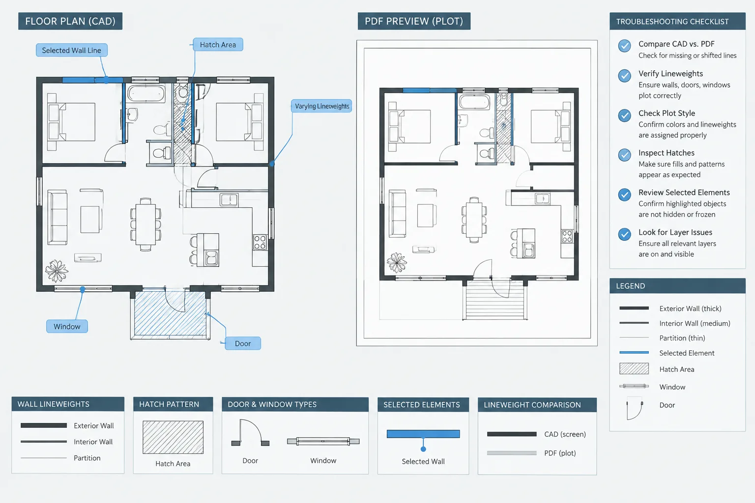
Plot or export a review copy and compare it side by side with the field sketches. Errors that are difficult to notice in model space often become obvious on a composed sheet. If possible, have someone who did not create the drawing perform a second review.
Preserve Traceability for Future Revisions
Keep the original field notes, photographs, and source files organized with the project records. Avoid replacing raw survey information with cleaned copies that remove uncertainty or corrections. The drafting file should also retain enough controlled reference geometry to explain how important locations were established.
Record the survey date and distinguish measured information from legacy drawing content. Buildings change, and a clear record of when and how the information was collected helps future users judge whether another site visit is necessary.
A Measured Drawing Is a Coordinated Interpretation
A strong existing-conditions plan is not created by forcing every field number into perfect geometry. It is produced by selecting reliable controls, understanding what each measurement represents, checking redundant information, and openly identifying what remains uncertain. Building the CAD plan from large verified geometry toward smaller features creates a more stable drawing and makes discrepancies easier to diagnose.
The result should be a clean, readable base that supports design while preserving the distinction between observed conditions, referenced information, and assumptions requiring further verification.
Prepare the Existing-Conditions File for Design Use
After the measured plan has been checked, create a clear handoff between survey information and proposed design work. Preserve a controlled version of the existing-conditions base before renovation geometry is added. This makes it easier to identify whether a later change came from a field correction, a drafting revision, or a design decision.
Layer names, object properties, notes, and referenced files should communicate the status of the information. Existing construction, items to be removed, proposed work, provisional geometry, and verification notes should remain distinguishable according to the project drafting standard. Avoid relying only on color if the drawing may be printed or exchanged with other users.
Document important drafting decisions
A short record of how the plan was established can be as useful as the finished linework. Document the primary baseline, the source of major control points, any legacy drawing used for context, and areas where field information did not reconcile. This record helps another drafter understand why geometry was placed as shown.
- Identify the field sketches and photographs associated with the CAD file.
- Record which building lines were treated as primary controls.
- Keep unresolved conditions visible on a managed verification layer.
- Separate measured geometry from objects inserted only for graphic context.
- Retain an issue or revision record when field corrections alter the base plan.
Coordinate edits without losing survey evidence
During design development, there may be pressure to straighten walls, align openings, or simplify irregular spaces. Proposed geometry may use those design intentions, but the existing-conditions base should continue to represent the verified survey. If the measured background is altered for presentation, preserve the original file and document the reason for the adjustment.
The most useful CAD base is therefore both readable and auditable. A future user should be able to distinguish direct measurements, coordinated interpretations, provisional references, and assumptions that still depend on site verification.
Frequently Asked Questions
Should every field measurement be entered into AutoCAD?
No. Measurements should first be interpreted according to their endpoints, purpose, and reliability. Redundant dimensions can be retained in the field record and used as checks without controlling separate pieces of geometry.
What should I do when field dimensions do not close?
Check whether the measurements use the same reference faces and origins. Compare them with overall dimensions, diagonals, photographs, and adjacent spaces. Keep the stronger control geometry, mark the unresolved condition, and seek additional verification when the difference affects design or construction decisions.
Should walls be forced square in the CAD plan?
Only when the available evidence supports that relationship. Existing walls may be angled, bowed, offset, or finished unevenly. Forcing orthogonal geometry can hide real conditions and create conflicts with other measurements.
Can an old floor plan be used as the starting point?
It can provide useful context, but it should be treated as reference information until current control points and dimensions are verified. Previous drawings may reflect earlier construction, unrecorded changes, or a different measurement basis.
How should inaccessible areas be shown?
Show only the information supported by observation or a clearly identified reference. Use a consistent note or verification marker rather than completing concealed geometry as though it were measured.
Why should temporary construction geometry be retained?
Baselines, measured points, triangulation arcs, and discrepancy markers explain how important locations were established. Keeping them on managed working layers supports checking and future revisions without cluttering the issued plan.
Can CAD blocks be used for existing fixtures and equipment?
Yes, when they are cleaned, scaled, and checked against observed extents. A generic block should communicate the object without implying that its exact shape, model, or installation was verified.