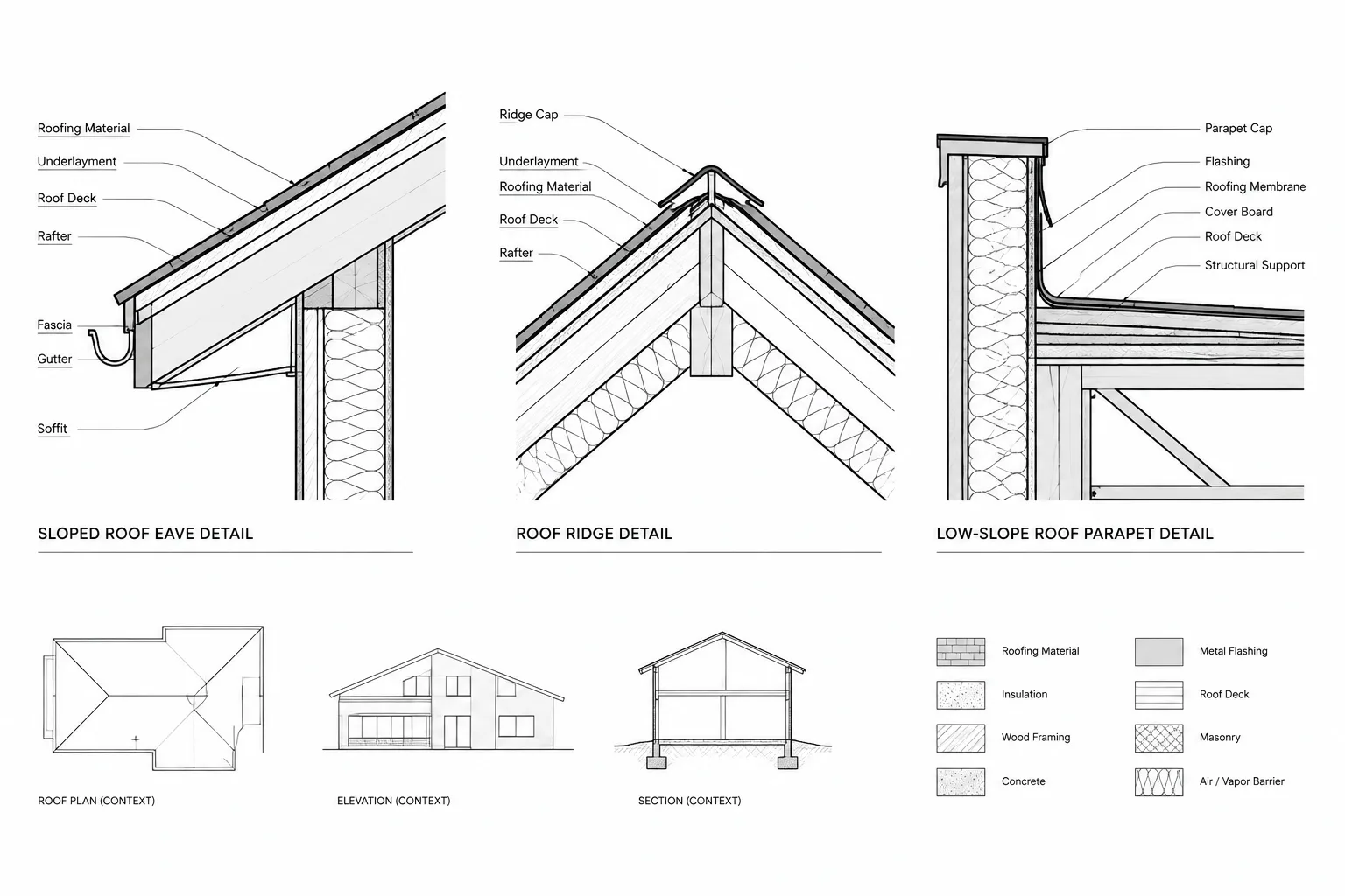
Drafting roof details in architectural CAD requires more than tracing an enlarged section. Eaves, ridges, and parapets are transition points where structure, insulation, finishes, waterproofing, flashing, and drainage must be coordinated in a readable construction view.
This guide presents a practical workflow for developing those details from verified project information. It focuses on geometric control, drawing hierarchy, layer organization, annotation, and cross-discipline review rather than prescribing a universal roof assembly.
Architectural roof details explain conditions that a roof plan cannot fully communicate. At eaves, ridges, and parapets, the drawing must show how the roof assembly terminates, changes direction, drains, and connects to walls or structural framing. These details also bring together information from architectural, structural, waterproofing, and mechanical drawings.
A useful roof detail is not simply an enlarged outline of the building. It should communicate the assembly in a clear visual order while leaving product-specific and engineering decisions to the appropriate verified sources. The following workflow focuses on drafting and coordination rather than prescribing a particular roof system.
Begin with the controlling project information
Before drawing detail geometry, collect the documents that control the condition. Depending on the project, these may include the roof plan, building sections, wall sections, structural framing drawings, exterior elevations, drainage layouts, and verified manufacturer information.
Review these sources for conflicts before developing the detail. Questions to resolve include:
- Which direction does the roof slope?
- Where is the structural roof line relative to the architectural finish?
- Does the wall continue above the roof as a parapet?
- Where does insulation change thickness or orientation?
- How does the weather-resistive or waterproofing layer continue through the condition?
- Where do roof edges, gutters, scuppers, drains, or overflow provisions occur?
- Which components are architectural, structural, or delegated to a specialty system?
Do not infer critical construction requirements from a generic CAD detail. Confirm actual assemblies, dimensions, attachment methods, drainage provisions, and performance requirements for the project.
Establish a reliable detail framework
Start with a section cut taken through the actual plan condition. Use grid lines, wall faces, structural edges, roof slopes, and level datums to establish the main geometry. If the source drawings are externally referenced, keep them as coordination backgrounds rather than tracing disconnected copies without verification.
Draw the largest controlling elements first:
- Primary wall or roof structure
- Roof deck or supporting substrate
- Wall and roof insulation zones
- Roofing or waterproofing layer
- Exterior wall finish and backup assembly
- Edge, coping, flashing, fascia, or drainage components
- Interior finishes and concealed accessories where relevant
This sequence reduces the risk of fitting major assemblies around small components that were drawn too early.
Represent thicknesses consistently
A detail should distinguish materials without becoming a product illustration. Draw assembly thicknesses according to verified project information. When an exact component has not been selected, use a clearly labeled diagrammatic representation rather than inventing a dimension.
Keep parallel material lines clean and avoid unnecessary overlapping segments. Closed polylines can be useful for material regions, while separate linework may be preferable for membranes, flashings, and other thin components that need to remain legible when plotted.
Drafting an eave detail
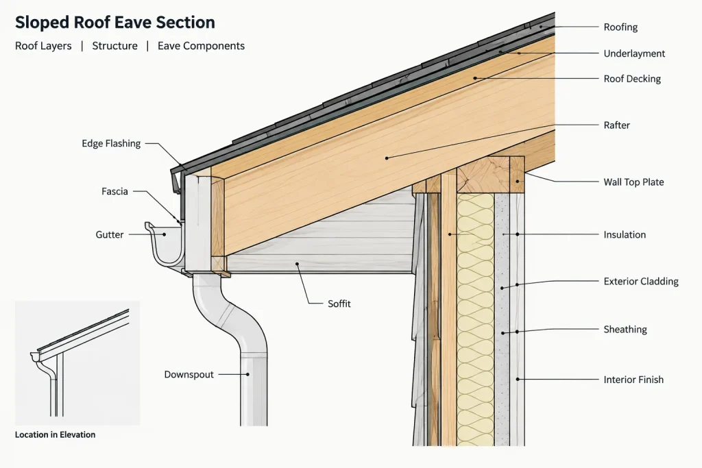
An eave is the lower roof edge where the roof commonly meets a fascia, gutter, soffit, or projecting overhang. The exact configuration varies with roof type, structure, drainage strategy, and exterior wall construction.
Coordinate the following relationships:
- The roof slope and structural support at the edge
- The termination of roofing or underlayment
- The relationship between edge flashing and the drainage component
- The fascia, soffit, and exterior finish alignment
- Ventilation paths where they are part of the verified assembly
- The continuity of insulation and environmental control layers
- The location of blocking, nailers, or supports identified by the responsible discipline
Show enough surrounding wall and roof construction to make the transition understandable. A tightly cropped detail that shows only flashing may conceal conflicts with the soffit, framing, or wall assembly.
On sloped roofs, confirm that the drawn edge condition follows the actual roof pitch and overhang geometry shown elsewhere. If gutters or downspouts are involved, coordinate their locations with the roof plan and exterior elevations. Avoid drawing drainage components as decoration without checking where water is intended to go.
Drafting a ridge detail
A ridge detail occurs where two sloping roof planes meet at a high point. Begin by extending both controlling roof slopes until they form the ridge geometry. Avoid adjusting one side by eye simply to make the detail appear symmetrical; the two roof planes may not have identical slopes or assembly depths.
The detail may need to identify:
- The supporting framing or structural ridge condition
- The roof deck or substrate on each side
- The meeting or separation of insulation layers
- The continuity of underlayment and roof covering
- A ridge cap, closure, or ventilation component when specified
- Interior ceiling geometry where it affects the assembly
If the ridge is ventilated, use verified design and product information to show the opening, vent component, and closure. Do not assume that every ridge is vented or copy a ventilation configuration from an unrelated roof system.
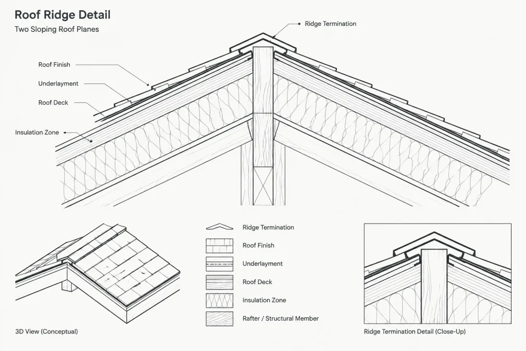
Ridge details should also be checked against sections and elevations. The ridge elevation, roof slopes, and finish profile should describe the same building geometry in every view.
Drafting a parapet detail
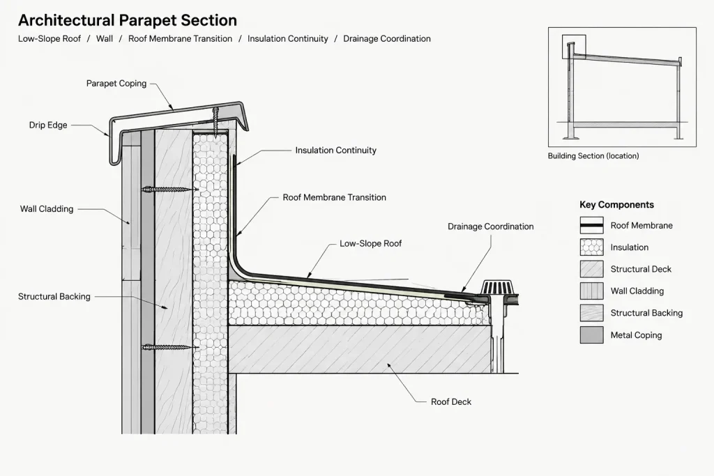
A parapet detail typically combines a low-slope roof edge with a wall that continues above the roof. It is a coordination-intensive condition because roofing, wall cladding, insulation, coping, structure, and drainage may intersect within a compact area.
Develop the detail from the structural wall and roof deck outward. Then add the roof assembly, wall assembly, membrane transition, and parapet termination. Important items to review include:
- Roof slope as it approaches the parapet
- The vertical continuation and termination of the roof membrane
- Continuity between roof and wall control layers
- Coping or cap geometry and its relationship to wall finishes
- Support or blocking indicated by structural or specialty information
- Movement provisions where required by the project design
- Scuppers, overflow paths, or adjacent drains shown in coordinated locations
Avoid treating the parapet as a solid generic rectangle. Even when the detail is schematic, the drawing should distinguish the wall structure, insulation, finishes, and roof transition so reviewers can follow the assembly.
Use a clear CAD graphic hierarchy
Roof details often contain many closely spaced lines. A deliberate hierarchy keeps the drawing readable.
| Graphic element | Recommended drafting role |
|---|---|
| Cut structure and major assemblies | Use prominent linework to define the primary sectioned form. |
| Visible edges beyond the cut | Use lighter lines so they do not compete with cut elements. |
| Membranes and flashings | Use distinct, continuous linework that remains visible at the plotted scale. |
| Insulation and material patterns | Use restrained hatches or symbols that do not obscure boundaries. |
| Background coordination geometry | Screen or lighten it when it is necessary for context. |
| Notes, leaders, and dimensions | Place them in open areas and avoid crossing important transitions. |
Keep hatches associative or otherwise controlled where practical, and check their plotted density. A pattern that looks clear while zoomed in may become a dark mass on the final sheet.
Organize layers by drawing purpose
Use the project layer system rather than creating detail-specific layers without a plan. Separate major categories such as structure, architectural outlines, overhead or beyond elements, hatches, membranes, annotations, dimensions, and reference backgrounds as required by the office standard.
Layer separation should support editing and plotting. It should not fragment one component across so many layers that the detail becomes difficult to maintain. If consultant geometry is shown for context, preserve its source identity or place it on controlled reference layers rather than presenting it as unverified architectural work.
Write notes that describe intent clearly
Use concise notes tied to visible components. Identify materials and transitions with terminology consistent with the project specifications and schedules. Avoid vague labels such as “typical flashing” when the drawing needs to distinguish between separate edge, base, counterflashing, or coping conditions.
Do not overload the detail with installation language copied from a product document. Include the information needed to understand and coordinate the architectural condition, then reference the appropriate project specification or verified detail source through the project’s established notation system.
Coordinate references across the drawing set
Every roof detail should have a traceable relationship to a plan, section, elevation, or larger-scale view. Confirm that detail callouts point to the correct sheet and detail location. If one detail applies to multiple locations, verify that those locations truly share the same assembly and geometry.
Review related drawings for consistency in:
- Roof edge and parapet profiles
- Level and elevation labels
- Roof slopes and drainage directions
- Wall and roof type designations
- Finish materials
- Drain, scupper, gutter, and downspout locations
- Structural framing relationships
When a condition varies, create a clearly identified variation rather than adding a small exception note that is easy to miss.
Perform a final roof-detail check
Before issuing the drawing, inspect the detail both on screen and at its intended plotted scale. Look for open material boundaries, duplicate lines, disconnected membranes, hatch conflicts, unsupported components, and leaders pointing to ambiguous locations.
Finally, compare the detail with current architectural and consultant backgrounds. A technically neat detail can still be wrong if it reflects an earlier roof slope, wall type, structural depth, or drainage layout. Treat eave, ridge, and parapet details as coordinated project views that must evolve with the building design, not as isolated library drawings.
Choose the detail boundary deliberately
The limits of a roof detail should provide enough context to explain how adjacent assemblies connect. Include the controlling roof and wall geometry, but avoid extending the view so far that the critical transition becomes difficult to find. The appropriate boundary depends on the coordination question the detail must answer.
For an eave, that context may include the roof edge, exterior wall, soffit, fascia, and drainage path. A ridge view should show enough of both roof planes to verify their relationship. A parapet view generally needs sufficient wall and roof construction to trace the transition between their control layers.
Separate verified information from unresolved design
A CAD detail can appear complete even when important decisions remain open. Use the project’s established notation method to identify unresolved components, consultant-dependent geometry, and product-specific conditions. Do not conceal missing information with generic linework or overly broad notes.
When backgrounds change, compare revisions rather than assuming the detail remains valid. Pay particular attention to shifts in roof geometry, wall construction, structural support, drainage location, and finish alignment. Update related callouts and dependent views as part of the same review.
Check continuity, constructability, and readability
A useful final review follows each assembly through the condition instead of checking individual objects in isolation. Trace the roofing or waterproofing, insulation, wall control layers, exterior finish, and structural support across the detail. A line that stops without a clear termination may indicate either incomplete drafting or an unresolved assembly.
Then review the drawing as communication. Confirm that leaders identify the intended component, notes use consistent terminology, material boundaries remain distinct, and background information does not compete with the sectioned work. This combined technical and graphic review helps turn a collection of CAD entities into a coordinated architectural detail.
Frequently Asked Questions
Should eave, ridge, and parapet details be drawn from a standard library?
A library detail can provide a drafting framework, but it should not be treated as verified project information. Rebuild or adapt the geometry using the current roof plan, sections, wall types, structural information, drainage design, and approved product data.
What should be drawn first in a roof detail?
Begin with controlling geometry such as structural edges, wall faces, roof planes, and level datums. Add the principal assembly zones before drawing flashings, membranes, accessories, and annotations. This keeps smaller components tied to reliable geometry.
How should thin membranes and flashings be represented in CAD?
Use distinct linework that remains legible at the intended plot scale. The representation should clearly communicate continuity, turns, laps, and terminations without implying an unverified thickness or product configuration.
When should separate roof-detail variations be created?
Create a variation when locations differ in geometry, assembly, drainage, support, finish, or termination. A single repeated detail should not be used merely because several conditions look similar on the roof plan.
How can a drafter identify coordination problems at a parapet?
Trace the roof and wall assemblies through the transition, then compare the result with structural and drainage information. Look for disconnected control layers, conflicting supports, unclear membrane terminations, incompatible finish alignments, and drainage elements that do not match other views.
Why should roof details be checked at plotted scale?
Closely spaced linework, dense hatches, small gaps, and crossing leaders may look acceptable while zoomed in but become unclear when plotted. Reviewing the intended sheet presentation reveals graphic conflicts that model-space inspection can miss.