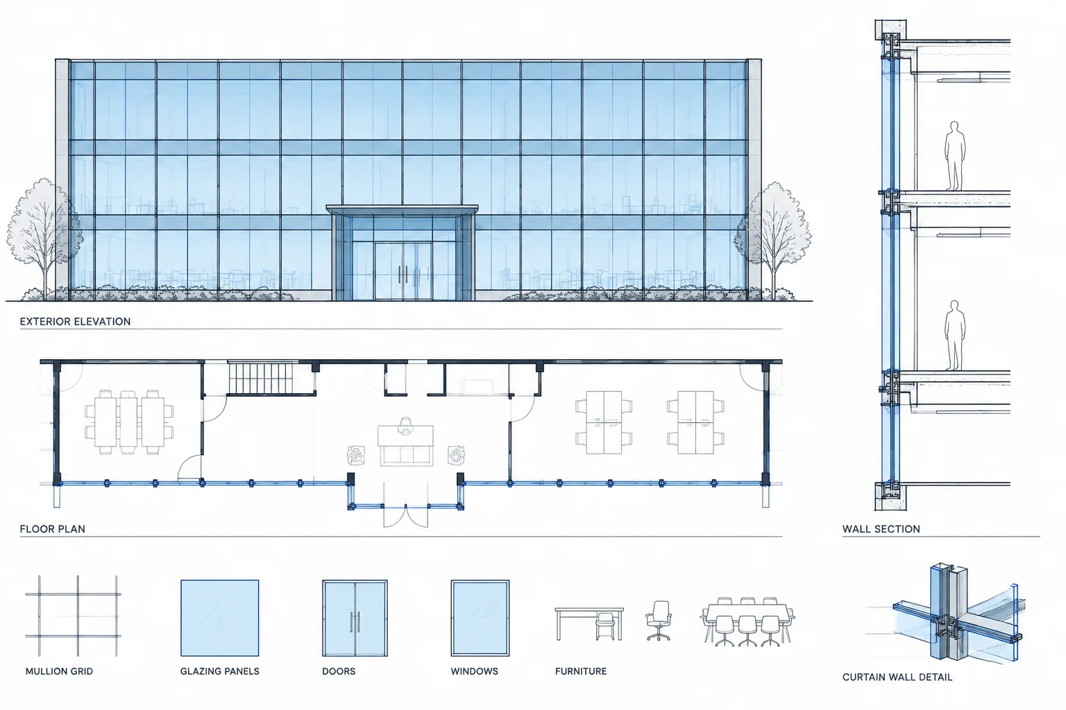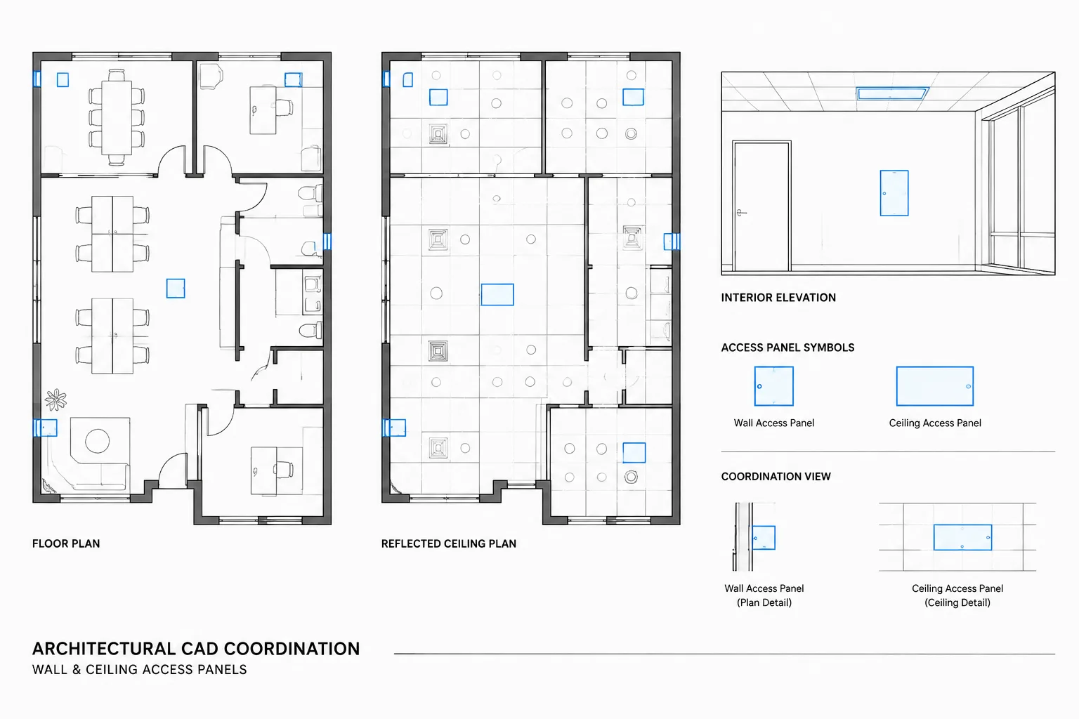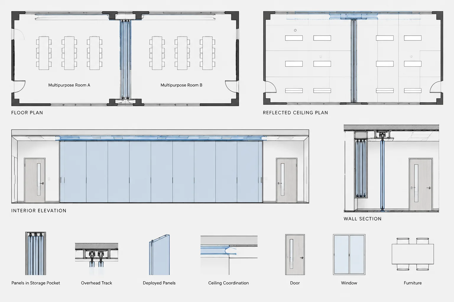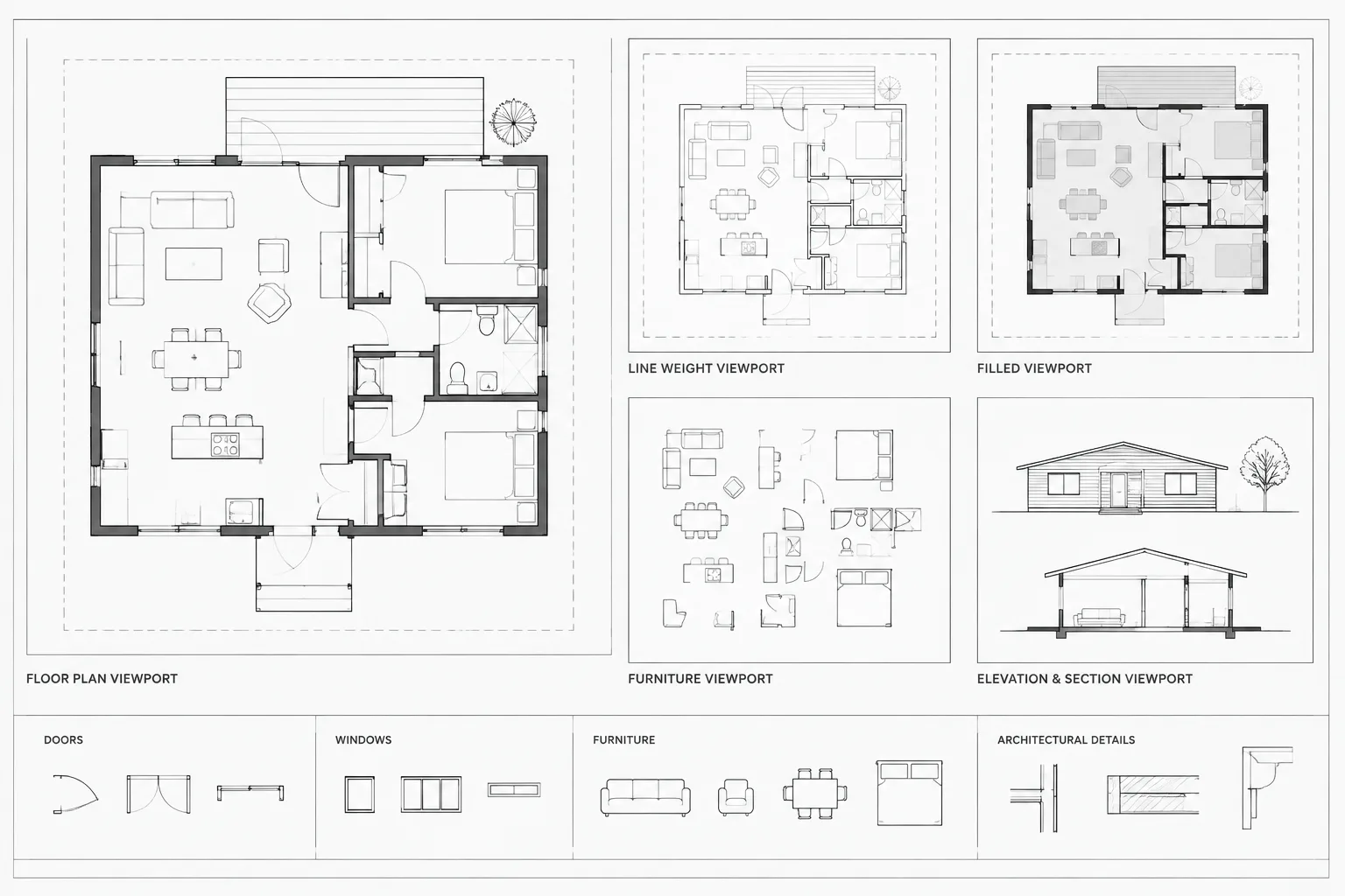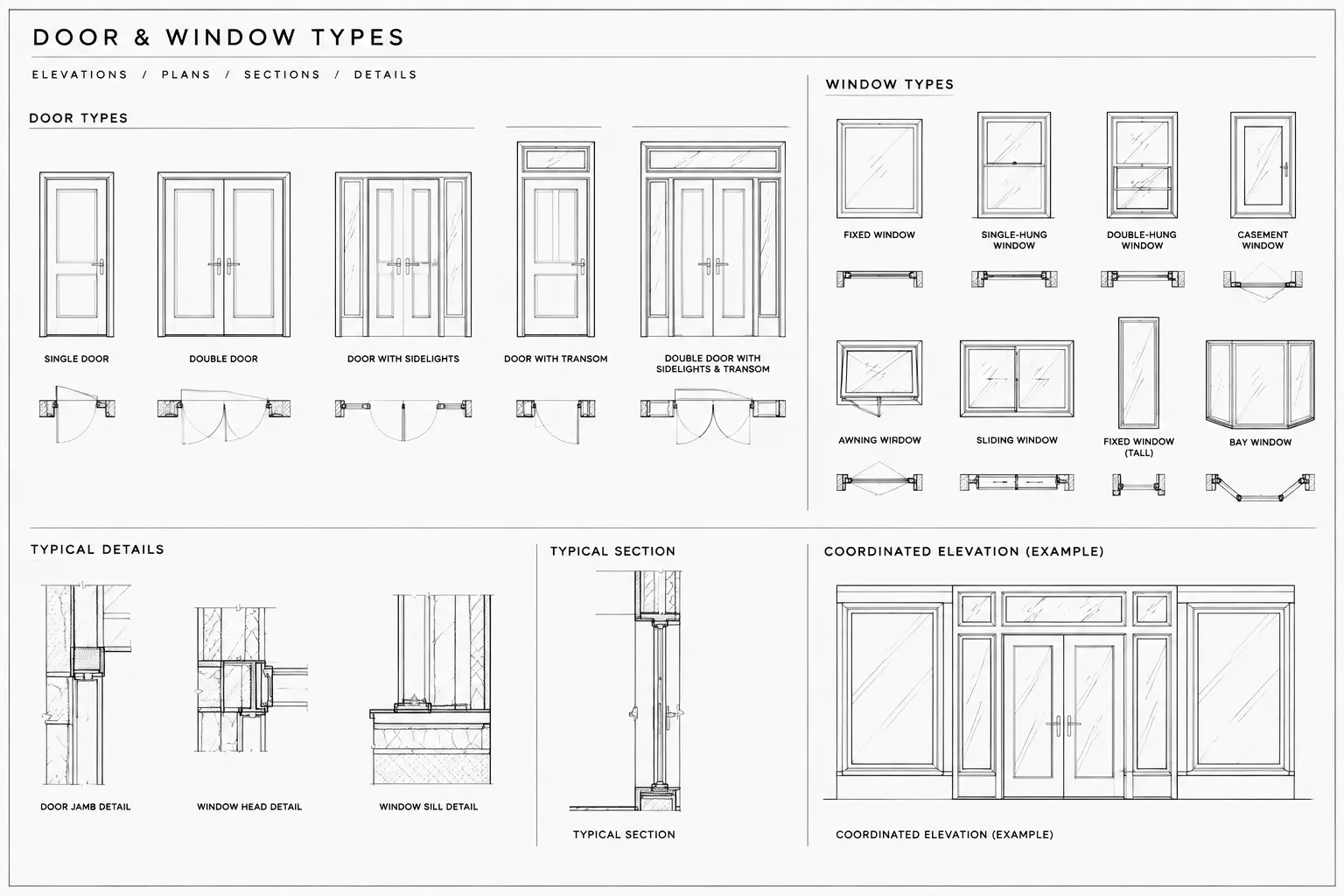
Door and window type elevations translate opening configurations into compact, repeatable CAD references. Their value depends less on decorative detail than on whether each drawing agrees with the plans, schedules, sections, specifications, and opening details.
This guide explains how to establish a clear viewing convention, build coordinated geometry, distinguish fixed and operable components, organize reusable CAD content, and review the completed type sheet. Use the workflow as a drafting framework, then apply the project’s established graphic standards and verified design information.
Door and window type elevations provide a visual catalog of the openings used in a project. Unlike building elevations, which show openings in their architectural context, type elevations isolate each door, frame, storefront, or window configuration so its geometry and identifying information can be reviewed clearly.
These drawings often sit between plans, schedules, specifications, and construction details. A type elevation may communicate panel arrangements, frame divisions, glazing locations, operable units, transoms, sidelights, and other features that are difficult to describe with a schedule entry alone. Because the same opening information can appear in several places, coordination is more important than graphic complexity.
What a type elevation should communicate
A useful type elevation answers a limited set of questions without trying to replace every related drawing. It should make the opening configuration recognizable, connect it to the correct identifier, and direct the reader toward schedules or details for additional information.
Depending on the project, a door or window type elevation may show:
- The overall opening or frame shape
- Door leaves, window units, sidelights, and transoms
- Major mullion, rail, stile, or panel divisions
- Glazed, opaque, louvered, or open areas
- Operable and fixed portions
- Typical overall and component dimensions
- A type mark that corresponds with the plan or schedule
- References to relevant head, jamb, sill, threshold, or anchorage details
Material descriptions, performance criteria, hardware, glazing composition, and product-specific requirements may belong in schedules or specifications instead. Decide where each category of information is controlled before drafting the elevations.
Understand marks, types, and individual openings
One common coordination problem is confusing an opening mark with a type designation. An individual mark usually identifies a particular door or window at a particular location. A type designation identifies a repeated configuration that may occur in several locations.
For example, multiple window marks may share one elevation type while differing in hardware, glazing, finish, or installation condition. Conversely, openings that appear similar may require different types because their configurations or interfaces are not actually the same.
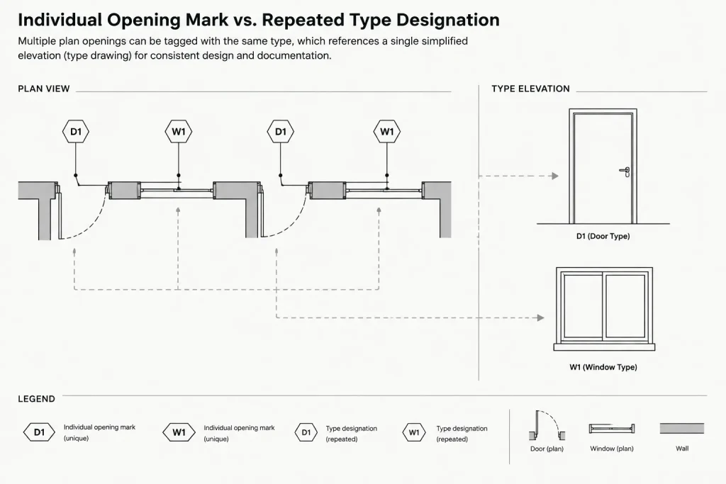
Establish the project’s identification logic before creating CAD labels. Do not assume that a downloaded block’s attribute names, numbering system, or tag format matches the project schedule.
Build the elevation from coordinated source information
Start with the plan and schedule
Review the floor plans to identify handing, frame depth, adjacent walls, grouped openings, and relationships to nearby construction. Then review the current schedule to confirm which marks share a type and which properties vary by opening.
If the type elevation and schedule disagree, do not select one arbitrarily. Determine which information reflects the current design decision and update the affected drawings together.
Use a consistent viewing convention
Define which side of the assembly the elevation represents. A door may look different from opposite sides, particularly when it includes unequal leaves, vision panels, louvers, hardware, or an asymmetric frame. Windows may also have interior and exterior distinctions.
State or graphically establish the viewing convention for the sheet. Avoid mirroring elevations simply to make them fit the layout; mirroring can reverse handing, operation, hardware relationships, and panel orientation.
Draft the primary frame geometry first
Begin with the overall frame or unit boundary. Add leaves, sashes, mullions, transoms, panels, and glazing divisions only after the outer geometry is stable. This sequence makes proportion errors easier to see and reduces the chance that internal elements drift beyond the frame.
Use construction lines or temporary reference geometry to align repeated rails, heads, sills, and panel divisions across related types. Remove or isolate temporary geometry before issuing the sheet.
Represent doors clearly
A door type elevation should distinguish the leaf from the frame and show meaningful divisions without becoming a fabrication drawing. The appropriate level of detail depends on the drawing scale and project phase.
Potential door features include:
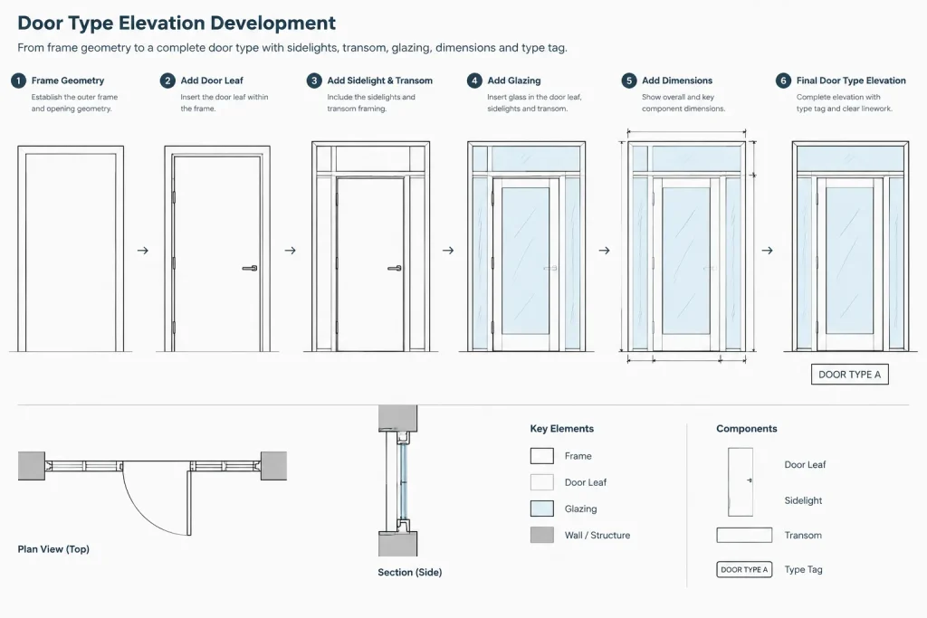
- Single, paired, unequal, sliding, folding, or other leaf arrangements
- Vision panels and glazed leaves
- Louvers or ventilation panels
- Flush, paneled, or framed leaf configurations
- Sidelights, borrowed lights, and transoms
- Frame heads, jambs, mullions, and intermediate rails
Use simplified linework for hinges, pulls, push plates, or other hardware only when it helps explain the design. The elevation should not conflict with the hardware set or imply unconfirmed product details.
Represent windows and glazed assemblies clearly
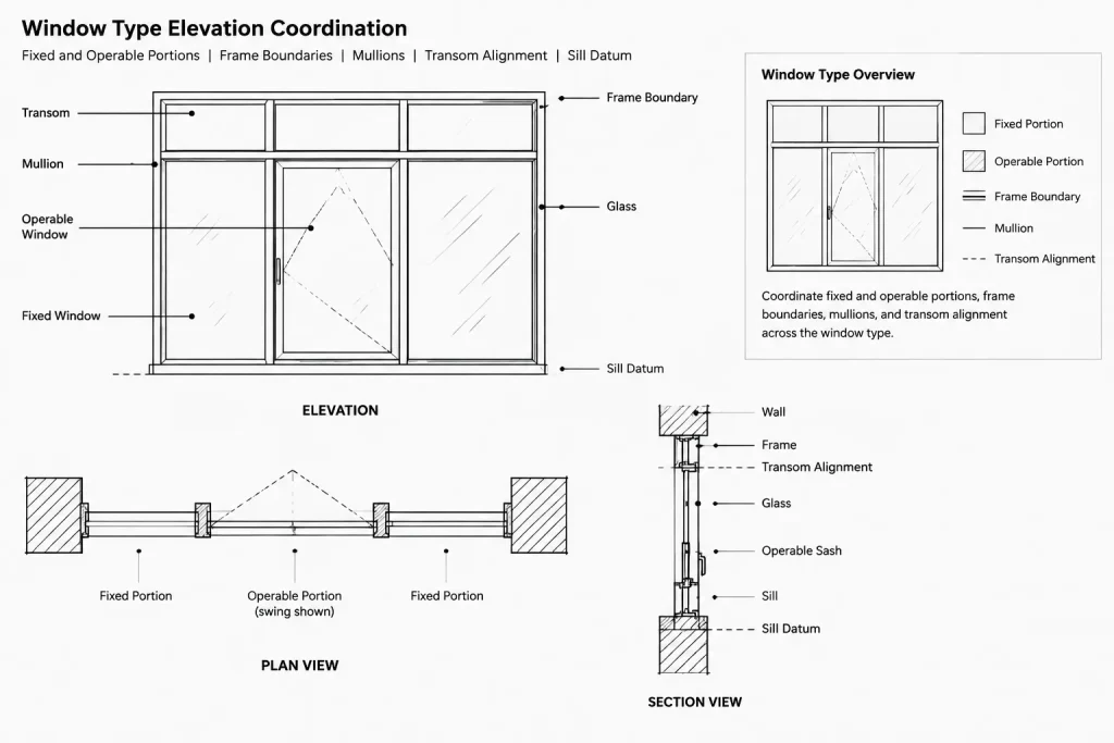
Window type elevations should make fixed and operable portions distinguishable. Use a consistent office convention for operation symbols, and include a legend when the symbol is not self-explanatory.
For grouped windows or glazed assemblies, draft the entire composition rather than showing one unit and relying on a note that may be overlooked. Clearly separate frame boundaries from internal glazing divisions. If a mullion is structurally, thermally, or visually different from a decorative grid, the drawings should not portray them as interchangeable.
Complex storefront, curtain wall, and custom glazed systems may require dedicated elevations and details rather than inclusion in a general window type sheet. Product geometry and fabrication requirements should be verified with the project team and applicable manufacturer information.
Choose dimensions that support coordination
Type elevations should include enough dimensions to define the intended configuration while avoiding redundant strings that are difficult to maintain. The exact dimensioning strategy should match the project’s documentation responsibilities.
| Dimension category | Typical purpose | Coordination concern |
|---|---|---|
| Overall width and height | Defines the main assembly extent | Confirm whether the project controls the rough opening, frame, unit, or another reference |
| Leaf or sash size | Clarifies operable component geometry | Avoid duplicating schedule data unless both locations are maintained together |
| Mullion and transom locations | Controls major visual divisions | Coordinate with adjacent finishes, elevations, and manufacturer constraints |
| Vision panel or louver location | Defines a feature within the leaf | Check hardware, accessibility, privacy, and other project requirements |
| Sill or head relationship | Connects the unit to architectural datums | Coordinate with floor levels, ceilings, exterior elevations, and details |
Do not infer dimensions from a generic CAD block. Confirm dimensions from approved project information, verified product data, or explicit design criteria.
Organize the CAD geometry for reliable editing
Place object categories on appropriate layers so frames, glazing, annotation, dimensions, and reference geometry can be controlled separately. Avoid placing an entire elevation on one layer if the project relies on layer-based plotting or visibility management.
Repeated type elevations can be managed as blocks when they are genuinely identical and should update together. Use attributes cautiously: an attribute may be appropriate for a type mark, but essential dimensions and notes should remain easy to review and edit. If similar elevations are likely to diverge, separate blocks may be safer than a single heavily customized block.
Keep type geometry at real model size unless the project uses another documented convention. Control plotted size through the established sheet and viewport workflow rather than scaling geometry to fit a sheet.
Coordinate the type sheet with related drawings
Door and window type elevations should be checked against more than the schedules. Review them alongside:
- Floor plans and enlarged plans
- Exterior and interior elevations
- Wall sections and opening details
- Finish information
- Ceiling conditions near heads and transoms
- Millwork or wall panel layouts
- Hardware, glazing, and product information when available
Pay particular attention to repeated datum relationships. A head height shown consistently in the type elevations may still conflict with a sloped ceiling, soffit, structural element, exterior coursing, or adjacent finish joint at a specific location.
Apply a focused quality-control review
Before issuing the drawing, perform a check that treats every type as part of a connected information system.
- Verify that every type identifier is unique and legible.
- Confirm that all referenced types are used, or clearly identify intentionally unused future types.
- Check that plan marks and schedule entries point to the correct type.
- Review asymmetric assemblies for accidental mirroring.
- Confirm that fixed and operable units are distinguishable.
- Compare overall dimensions with schedules and coordinated elevations.
- Check head, sill, transom, and mullion alignments against adjacent construction.
- Remove obsolete options, hidden geometry, and abandoned labels.
- Plot a test sheet to verify lineweight, text size, symbols, and hatch clarity.
Use type elevations as coordination drawings
The best door and window type elevations are not decorative catalogs. They are compact coordination drawings that connect opening geometry with plans, schedules, elevations, sections, and details. A disciplined CAD workflow—based on controlled identifiers, consistent viewing conventions, verified dimensions, and deliberate cross-checking—makes these sheets easier to read and safer to revise.
Generic door and window CAD blocks can provide a drafting starting point, but they should be cleaned, scaled, relayered, and verified before becoming project information. Final configurations must reflect the actual design, project requirements, applicable regulations, and confirmed product constraints.
A practical revision workflow
Revisions to an opening should be treated as coordinated information changes rather than isolated CAD edits. Before modifying a type elevation, identify every drawing or document that uses the affected mark, type, dimension, operation, or detail reference.
Trace the source of the change
Determine whether the revision began with a plan adjustment, design elevation, schedule entry, product decision, detail condition, or field coordination item. This helps establish which information is intentional and which related content has become outdated.
Update geometry before annotation
Revise the frame boundary, leaves, sashes, panels, glazing divisions, and other defining geometry first. Then update dimensions, type marks, operation symbols, notes, and detail references. This order reduces the risk of retaining annotation that describes an earlier configuration.
Check every occurrence
A type may appear in several locations even when its elevation is drawn only once. Review the plans and schedules to determine whether the change applies to every opening assigned to that type. If only selected openings change, consider whether they now require a separate type rather than exceptions buried in notes.
Review the plotted result
Inspect the sheet at its intended output condition. Confirm that frames remain visually distinct from leaves and glazing, operation symbols are readable, dimensions do not merge with geometry, and type labels can be found quickly. CAD linework that appears clear while zoomed in may not communicate properly on the issued sheet.
Graphic hierarchy for type elevations
A restrained hierarchy makes an opening easier to interpret. The primary assembly boundary should read first, major internal divisions second, and annotation or reference information third. Glazing indicators, operation symbols, hardware cues, and material patterns should remain subordinate unless they communicate a critical distinction between types.
Avoid using extra linework merely to make an elevation look realistic. Every visible element can be interpreted as project information. If a profile, joint, panel, grid, or hardware item has not been confirmed, use an appropriately simplified representation rather than implying a product-specific condition.
When a separate type is warranted
Two openings should not automatically share a type simply because their overall shapes look similar. A separate type may be appropriate when the panel arrangement, operation, handing relationship, frame composition, transom or sidelight layout, or interface with adjacent construction is meaningfully different.
Minor properties controlled elsewhere may not justify another elevation. The project team should decide which differences are graphical type distinctions and which belong in schedules, hardware information, glazing information, finishes, or specifications. Applying that logic consistently keeps the type sheet useful without creating unnecessary variants.
Frequently asked questions
What is the difference between a door or window type elevation and a building elevation?
A type elevation isolates an opening assembly so its configuration and identifier can be reviewed. A building elevation shows the opening within the larger architectural composition, including surrounding walls, finishes, datums, and adjacent elements.
Should every door or window mark have its own elevation?
Not necessarily. Several individually marked openings may reference one shared type when their relevant configurations are the same. Differences controlled by schedules or specifications do not always require separate type drawings, but meaningful geometric or operational differences may.
Can downloaded CAD blocks be used directly?
Downloaded blocks can provide starting geometry, but their dimensions, layers, attributes, symbols, linework, and naming conventions must be checked. They should not be treated as verified project information until coordinated with the actual design.
Should hardware be shown in a door type elevation?
Show simplified hardware only when it helps explain the configuration or distinguishes one type from another. Avoid drawing product-specific hardware that has not been confirmed, and coordinate any representation with the project’s hardware information.
How should operable window units be identified?
Use the project or office convention for operation symbols and apply it consistently. Add a legend when readers may not understand the symbol without explanation, and verify that the indicated operation agrees with plans, schedules, and exterior or interior orientation.
Why should type elevations not be mirrored casually?
Mirroring can reverse handing, operation, unequal leaves, vision panels, hardware relationships, and asymmetric frame divisions. Confirm the viewing direction and intended configuration before using mirrored geometry.
Where should detailed material and performance information go?
Type elevations should show the information needed to recognize and coordinate the configuration. Extensive material descriptions, performance criteria, glazing composition, hardware requirements, and product-specific data may be better controlled in schedules or specifications.