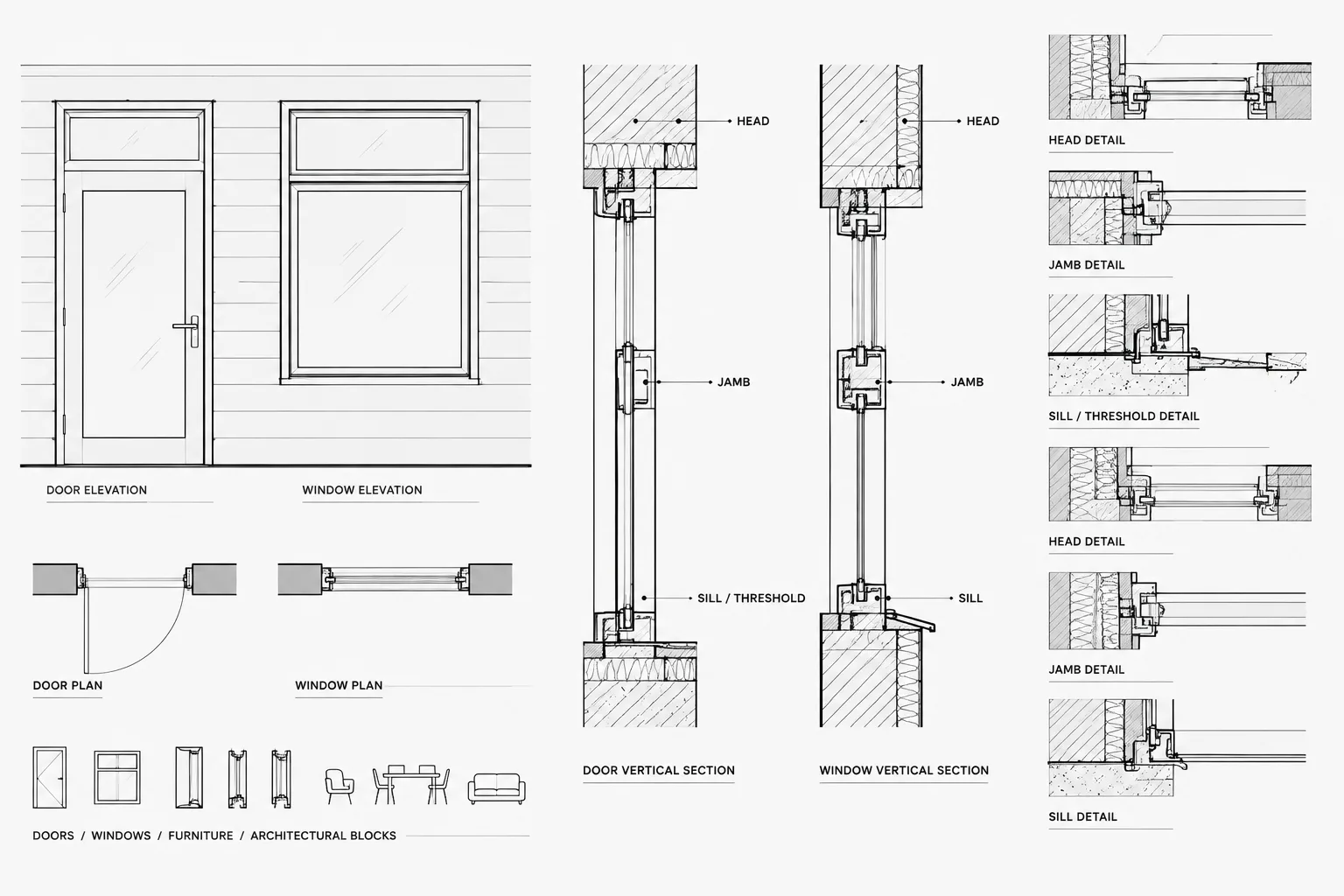
Door and window details sit at the intersection of architectural design, wall construction, product selection, structural support, finishes, and water management. Drafting them effectively requires more than tracing a frame profile: each view must explain how the opening interfaces with the surrounding assembly.
This guide presents a practical workflow for developing coordinated head, jamb, sill, and threshold details in CAD. It emphasizes drawing organization, source verification, graphic clarity, and coordination without substituting generic geometry for project-specific product or consultant information.
Door and window details explain how an opening is formed, supported, finished, sealed, and connected to adjacent construction. Although floor plans and elevations establish the opening location and general appearance, head, jamb, sill, and threshold details communicate the relationships that cannot be shown clearly at a smaller drawing scale.
A useful CAD detail is not simply an enlarged outline of a frame. It must coordinate the wall assembly, opening dimensions, frame profile, finishes, structure, water-management strategy, interior transitions, and references to related information. The following workflow focuses on organizing that information clearly while avoiding unsupported assumptions about a proprietary product or project-specific requirement.
Begin with the Opening, Not the Frame Profile
Before drawing a detailed frame extrusion, establish the architectural conditions around the opening. Identify the wall type, structural opening, exterior and interior finishes, frame location within the wall, and the direction in which the assembly is viewed.
Confirm the following source information:
- The corresponding door or window mark on the plan and elevation
- The wall type and total wall build-up at the opening
- The rough or structural opening information provided by the appropriate consultant or manufacturer
- The selected frame, glazing, door, or window system
- Interior and exterior finish returns
- Sill, threshold, flashing, sealant, and drainage concepts
- Structural lintel, header, edge, or support conditions
If product information is not yet available, draft a clearly identified design-intent condition rather than inventing a profile. Generic details can establish relationships and responsibilities, but they should not imply that an unverified frame shape, anchor pattern, or flashing configuration belongs to the final product.
Set Up a Consistent Detail Family
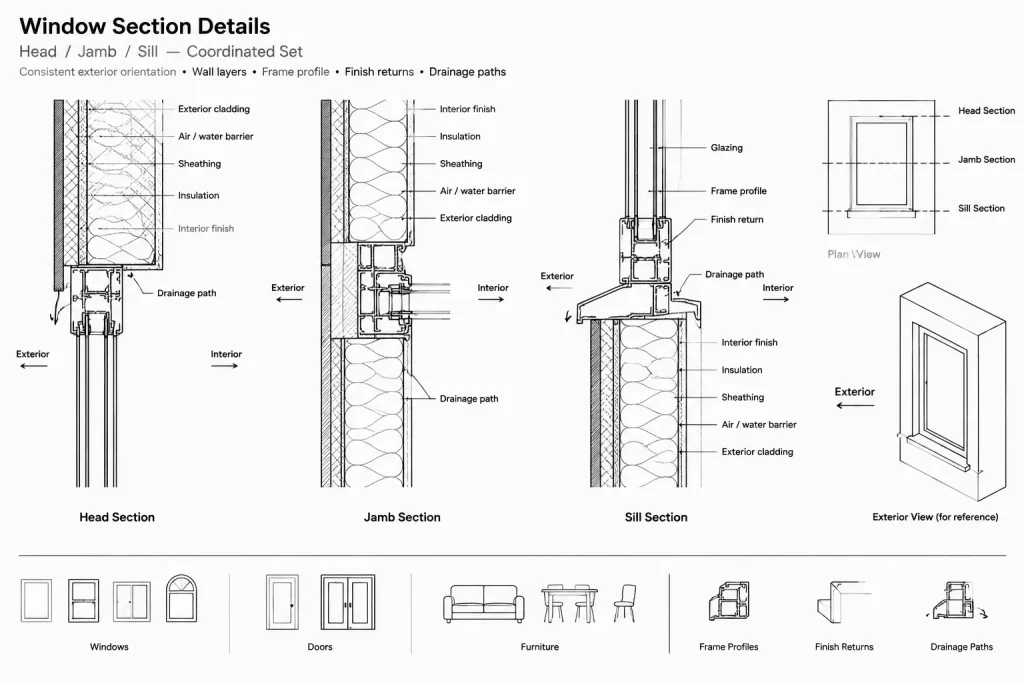
Head, jamb, sill, and threshold details should be treated as a coordinated family. Use the same orientation, graphic hierarchy, terminology, and material representation throughout the set.
A practical arrangement may include:
- A vertical head section showing the top of the opening
- A horizontal jamb section showing the side condition
- A vertical sill section for windows or glazed openings
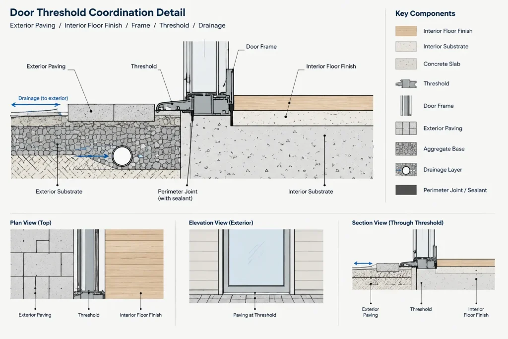
- A vertical threshold section for doors
- Separate details where interior and exterior conditions differ substantially
Keep the exterior side consistently located when possible. For example, vertical details can place the exterior on one side of the drawing, while horizontal details can use a consistent viewing direction. Add orientation labels when the relationship is not immediately obvious.
Build the Detail from Large Components to Small Components
Drafting in a deliberate sequence reduces conflicts and prevents the frame from controlling conditions that should be established by the wall or structure.
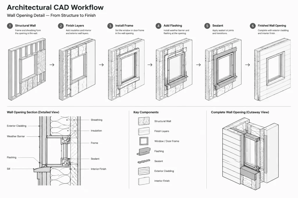
1. Draw the primary wall and structure
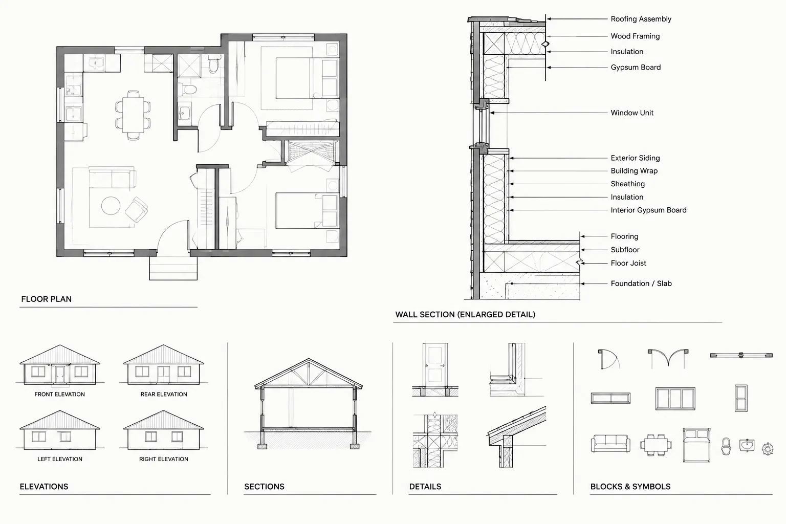
Start with the major construction boundaries: structure, backup wall, sheathing, cavity, insulation, cladding, interior finish, and floor or roof edge where relevant. Use the project wall type as the source rather than recreating the assembly from memory.
At this stage, verify whether the opening interrupts continuous layers. A detail should reveal how those layers return, stop, bridge, or connect around the opening.
2. Locate the opening and frame
Place the frame relative to the wall assembly. Its position may affect finish returns, exterior projections, interior stools, shading, and perimeter transitions. Coordinate the location with both the floor plan and exterior elevation.
If a product profile is inserted from a manufacturer drawing, isolate and review it before use. Remove unrelated annotations, confirm drawing units, check the section orientation, and retain only geometry needed to explain the architectural condition.
3. Add finishes and closure pieces
Show how interior and exterior finishes terminate at the opening. Typical questions include whether a finish returns to the frame, ends at a trim piece, aligns with a reveal, or requires a closure component.
Avoid drawing finish lines through the frame or leaving unexplained gaps. Small finish transitions often reveal coordination problems that are difficult to see on plans.
4. Add environmental transition concepts
Show the intended relationship among flashing, membranes, sealant joints, backer material, pans, end conditions, and drainage paths where those elements apply. The exact configuration must be coordinated with the specified system and project team.
Draw these elements with enough separation to remain legible. A membrane represented by a bold or distinctive line should not disappear beneath hatch patterns. Use leaders to identify elements that cannot be drawn literally at the detail scale.
5. Add support and attachment information
Indicate the relationship between the frame and supporting construction without inventing anchors or fastener spacing. Where attachment design is provided by a manufacturer, engineer, or specialty contractor, use an appropriate reference or coordination note rather than a fabricated solution.
What Each Detail Needs to Explain
| Detail | Primary coordination questions |
|---|---|
| Head | How is the opening supported? How do wall layers pass over or terminate above the frame? Where do flashing and finish transitions occur? |
| Jamb | Where is the frame positioned in the wall? How do finishes return? How are perimeter joints, closures, and adjacent wall components coordinated? |
| Window sill | How is water directed away from the opening? How do the sill, pan, interior stool, wall layers, and frame connect? |
| Door threshold | How do exterior paving, interior flooring, substrate, frame, and threshold meet? Are level changes and drainage conditions accurately represented? |
Coordinate the Detail with Plans, Elevations, and Schedules
A detail may look convincing while contradicting the rest of the drawing set. Check it against every drawing that controls the opening.
- Floor plan: Confirm wall thickness, frame location, swing, recesses, projections, and adjacent finishes.
- Building elevation: Confirm head and sill alignment, trim width, joint locations, and relationships to cladding modules.
- Interior elevation: Confirm casing, reveals, stools, base conditions, and nearby millwork.
- Door or window schedule: Confirm the mark, type, material description, glazing designation, and associated notes.
- Wall section: Confirm floor, structure, envelope, roof, and wall-layer continuity.
- Structural drawings: Confirm the opening support concept and avoid duplicating information that belongs to structural documentation.
When the same opening type occurs in several wall assemblies, do not assume one detail fits every location. A frame installed in a framed wall may require a different condition from the same frame at masonry, concrete, rainscreen, or interior partition construction.
Use CAD Layers to Separate Meaning
Organize detail geometry so that it can be edited and plotted predictably. The exact layer names should follow the project standard, but useful categories commonly distinguish:
- Cut construction and profile outlines
- Beyond or background geometry
- Hatches and material poche
- Membranes, flashing, and sealant graphics
- Dimensions
- Leaders and notes
- Detail references and titles
- Consultant or manufacturer reference geometry
Avoid placing an entire imported detail on one layer. Separating information by function makes it easier to control lineweight, remove redundant content, and update the assembly.
Apply a Clear Graphic Hierarchy
Elements cut by the section plane should read more strongly than surfaces seen beyond. Primary frame and wall boundaries need more visual weight than internal profile lines. Hatches should identify materials without overwhelming joints, membranes, or annotations.
At the intended plotted scale, inspect areas where many components meet. Common trouble spots include narrow cavities, frame receptors, finish returns, threshold edges, and overlapping leaders. If the assembly becomes unreadable, simplify secondary profile geometry while preserving the relationships needed for construction coordination.
Dimension Relationships, Not Every Line
Detail dimensions should communicate controlling relationships. Excessive dimensions can conflict with schedules, product information, and larger-scale drawings.
Useful dimensional subjects may include:
- Frame position relative to a controlling wall face
- Opening or recess relationships that are not controlled elsewhere
- Critical finish offsets or alignments
- Sill, head, or threshold elevations tied to project datums
- Required coordination clearances when verified by the project team
Do not derive field dimensions from a generic CAD block. Product rough openings, tolerances, installation joints, and anchor requirements must come from verified project sources.
Avoid Common Drafting Errors
- Using a generic profile as a final product: A downloaded frame section may not match the selected system.
- Ignoring the wall type: An opening detail is incomplete if it shows a frame without the actual wall build-up.
- Breaking continuity without explanation: Insulation, membrane, flashing, and finish transitions should not stop arbitrarily.
- Contradicting the elevation: Trim, reveals, and cladding joints must align with the exterior design.
- Overdrawing proprietary geometry: Tiny internal extrusion lines can obscure the architectural interfaces.
- Inventing attachments: Unverified fasteners and spacing create false technical authority.
- Reusing details without checking orientation: Mirrored or reversed openings may change drainage, handing, or adjacent conditions.
Final CAD Review Checklist
Before issuing the detail, perform a focused review:
- Verify the door or window mark and referenced wall type.
- Confirm that head, jamb, sill, and threshold details describe the same frame family.
- Check exterior and interior orientation.
- Compare frame placement with the floor plan and elevations.
- Confirm that finish returns and cladding joints are represented consistently.
- Review flashing, membrane, sealant, and drainage concepts with the appropriate project information.
- Check structural opening and support conditions against consultant drawings.
- Remove duplicate lines and unnecessary imported profile geometry.
- Test hatches, lineweights, leaders, and text at the intended plot scale.
- Flag unresolved product or installation information instead of guessing.
Well-coordinated door and window details connect design intent with constructible interfaces. By building each detail from the wall assembly outward, checking it against related drawings, and clearly distinguishing verified information from placeholders, CAD users can produce details that are easier to review, update, and use throughout the project.
Manage Verified and Unresolved Information
Opening details often develop while product selection, structural support, and installation requirements are still being coordinated. The CAD file should make that uncertainty visible rather than concealing it behind precise-looking geometry.
During development, distinguish among information confirmed by the architectural set, geometry supplied by a manufacturer or consultant, and conditions that remain subject to coordination. Use concise notes or drawing-status conventions that follow the project standard. When information is updated, review the complete detail family instead of correcting only the view where the change was first identified.
Trace Each Condition to Its Source
- Architectural drawings: Wall assembly, frame placement, finish relationships, design intent, and drawing references.
- Product information: Verified frame profiles, glazing components, accessories, installation interfaces, and manufacturer-defined terminology.
- Structural information: Opening support, edges, headers, lintels, and supporting substrates.
- Envelope coordination: Membrane continuity, flashing relationships, perimeter joints, drainage paths, and transitions between systems.
- Interior coordination: Finish returns, casing, stools, flooring, base, adjacent millwork, and accessibility-related design information where applicable.
Review Changes as Connected Interfaces
A change to frame depth or placement can affect finish returns, perimeter joints, sill geometry, threshold alignment, flashing transitions, and elevation appearance. Compare revised details with plans, elevations, schedules, wall sections, and related opening details before considering the update complete.
Keep imported reference geometry identifiable and editable. This helps reviewers understand which elements came from an external source and which were created to communicate the architectural interface. It also reduces the risk of treating an outdated product profile as current project information.
Prepare the Detail for Issue
Before publishing or issuing the CAD drawing, perform both a technical review and a plotted graphic review. The technical review asks whether the interfaces agree with verified project information. The graphic review asks whether cut elements, background components, membranes, finishes, notes, and references remain distinguishable when the drawing is printed or exported.
A successful detail should communicate where each assembly begins and ends, how adjacent components relate, and where additional information governs. It should not create false certainty by showing unsupported anchors, dimensions, profiles, or installation methods.
Frequently Asked Questions
What is the difference between a head, jamb, sill, and threshold detail?
A head detail is a vertical section through the top of an opening, while a jamb detail is a horizontal section through its side. A window sill detail explains the lower window interface and its relationship to drainage and finishes. A door threshold detail coordinates the bottom of the door assembly with flooring, paving, substrates, and adjacent transitions.
Should a manufacturer CAD profile be used without editing?
No. Review its units, orientation, drawing status, and relevance to the selected system before placing it in the architectural detail. Remove unrelated annotations and unnecessary internal geometry, but retain the verified profile information needed to explain the interface.
How much of the wall assembly should an opening detail show?
Show enough surrounding construction to explain support, finish returns, frame placement, environmental transitions, and continuity with the applicable wall type. A frame drawn without its surrounding wall layers rarely provides sufficient coordination information.
Should every component in the detail be dimensioned?
No. Dimension controlling relationships that are verified and not governed more appropriately elsewhere. Avoid repeating product data, schedule information, or dimensions that may conflict with other project documents.
How should missing product information be handled?
Represent the condition as design intent and clearly identify unresolved interfaces. Do not invent frame shapes, anchors, clearances, flashing configurations, or installation requirements. Update the detail when verified information becomes available.
Why should head, jamb, sill, and threshold details be reviewed together?
They describe different sections through the same opening system. Reviewing them as a family helps detect inconsistent frame placement, finish treatment, terminology, wall construction, and environmental transitions.