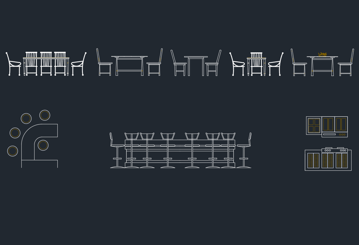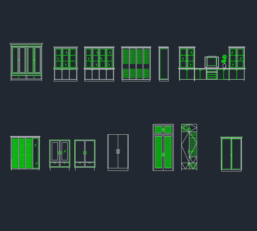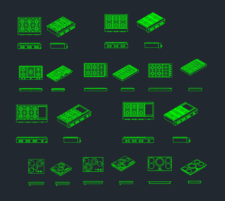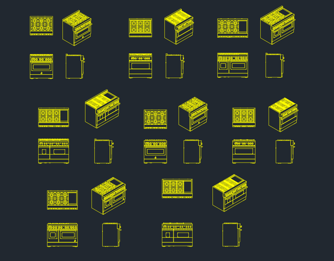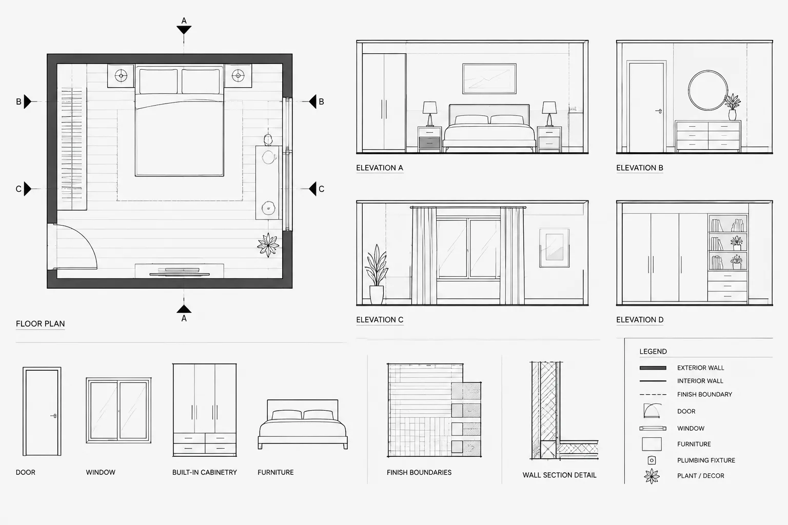
Drafting interior elevations requires more than projecting room elements onto a flat wall view. Each elevation must communicate vertical design intent while remaining coordinated with plans, schedules, sections, details, and referenced consultant information.
This guide presents a practical CAD workflow for selecting necessary views, establishing reliable references, organizing linework and annotation, checking finish and fixture relationships, and managing revisions. Use it as both a drafting method and a review framework before drawings are issued.
Interior elevations explain the vertical design of a room in ways that a floor plan cannot. They show cabinetry, wall finishes, doors, windows, fixtures, equipment, trim, accessories, and other elements as viewed straight toward a wall. Because these drawings bring many building components together, they are also frequent locations for coordination errors.
A dependable interior elevation workflow starts with the plan rather than with isolated linework. The elevation should remain traceable to its room, viewing direction, related details, and current design information. The goal is not simply to produce an attractive drawing. It is to create a view that can be checked against the rest of the architectural set and updated without ambiguity.
Decide Which Walls Need Interior Elevations
Not every wall requires a drawn elevation. Select views according to the information that must be communicated. A wall may need an elevation when it contains custom millwork, plumbing fixtures, equipment, several finish transitions, coordinated accessories, feature lighting, or a complicated arrangement of openings.
Simple walls may be adequately described by the floor plan, room finish information, schedules, and typical details. Drawing unnecessary elevations increases maintenance work and creates more opportunities for conflicting information.
Before drafting, review each room and ask:
- Does the wall contain work that cannot be located clearly in plan?
- Are vertical relationships important to installation or design intent?
- Does the wall require coordination among several trades or drawing disciplines?
- Would a typical elevation apply, or is the condition unique?
- Is an elevation sufficient, or is a section or enlarged detail also needed?
Establish a Clear Relationship to the Floor Plan
Every interior elevation should have an identifiable source location. Place elevation markers in the plan so the reader can determine which wall is shown and in which direction the viewer is looking. Keep marker symbols, view identifiers, and sheet references consistent with the project annotation system.
The view boundary also matters. Decide whether the elevation represents an entire wall, a portion of a wall, or a grouped set of room elevations. Avoid cropping away adjacent corners when those corners are needed to understand where finishes, counters, or wall-mounted components terminate.
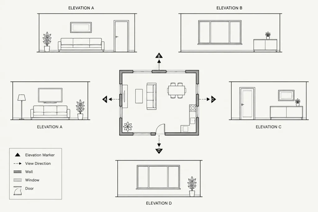
Elevation markers should be checked whenever room layouts change. A shifted partition, revised door, or relocated casework run may make an existing marker inaccurate even if the elevation drawing itself still appears plausible.
Build the Elevation from Coordinated References
Begin with current plan geometry and established vertical datums. Project or reference the wall limits, openings, floor line, ceiling condition, and major fixed elements before adding detail. If the project uses external references, confirm that the correct files and revisions are loaded. Avoid tracing an outdated plot or detached copy when coordinated CAD geometry is available.
A practical construction order is:
- Establish the finished floor or other project datum used by the drawing set.
- Set the left and right limits of the viewed wall.
- Locate doors, windows, wall returns, columns, and major recesses from the plan.
- Add ceiling edges, soffits, bulkheads, and other overhead conditions.
- Place fixed cabinetry, counters, fixtures, equipment, and accessories.
- Add finish extents, joints, trim, panels, and other visible surface divisions.
- Apply annotation only after the principal geometry has been checked.
Plan and elevation geometry should share a common design source wherever practical. If the same cabinet layout is redrawn independently in several files, minor revisions can quickly produce contradictory views.
Use Graphic Hierarchy to Explain Depth
An interior elevation is a projected view, but it still needs a readable sense of depth. Objects at the primary wall plane generally require stronger emphasis than secondary surface patterns. Elements seen beyond an opening or behind the principal plane should be visually quieter.
Use the project layer and plotting system to distinguish among:
- Primary outlines and profile edges
- Visible component edges
- Surface joints and finish patterns
- Objects beyond openings
- Hidden or overhead information when relevant
- Dimensions, notes, tags, and reference symbols
Do not depend on color alone to communicate meaning. The elevation must remain legible in its intended plotted output. Dense hatch patterns, excessive joint lines, and detailed manufacturer graphics can obscure the architectural information. Simplify imported content and CAD blocks to the level appropriate for the drawing.
Coordinate the Main Information Categories
| Information | What to verify | Related drawings |
|---|---|---|
| Openings | Location, extent, type tags, trim, and head or sill relationships | Floor plans, door schedule, window schedule, details |
| Millwork | Overall arrangement, modules, counter edges, appliance openings, and panel alignment | Plans, millwork details, equipment information |
| Fixtures and accessories | Wall location, vertical relationship, conflicts, and identification | Plumbing plans, equipment plans, accessory schedules |
| Finishes | Material extents, transitions, termination points, and joint intent | Finish plans, finish schedules, enlarged details |
| Ceiling conditions | Ceiling edge, soffits, bulkheads, and coordination with wall-mounted work | Reflected ceiling plans and sections |
| Annotation | Dimensions, notes, tags, and detail references | Legends, schedules, specifications, and referenced details |
Dimension Design Intent, Not Every Line
Interior elevations can become unreadable when every visible edge receives a dimension. Prioritize dimensions that locate design-controlled elements and clarify important vertical or horizontal relationships. Repeated modules may be explained by an overall dimension, a typical condition, or a referenced detail rather than by a long chain of redundant dimensions.
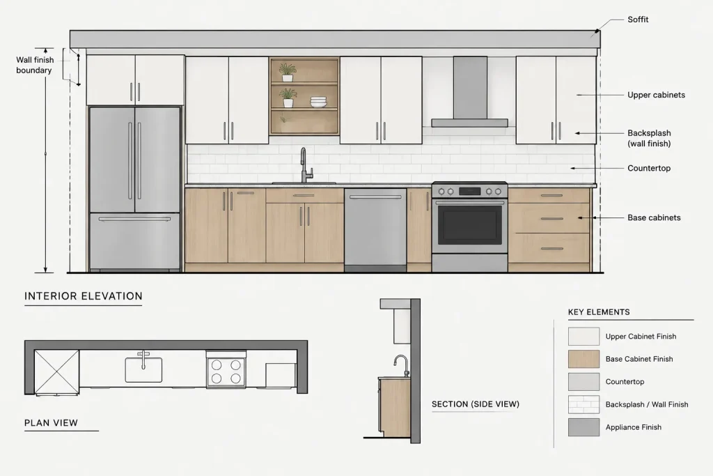
Organize dimensions in clear bands where possible. Keep dimensions outside dense geometry unless placing one near an object substantially improves comprehension. Avoid duplicating information that is already controlled by another drawing unless the repetition serves a clear coordination purpose.
Dimensions should be based on verified project geometry, not estimated from a block or scaled from a presentation image. Product-dependent information should be checked against the selected product data and project requirements before issue.
Handle Finishes and Surface Patterns Carefully
Interior elevations are often used to show tile layouts, wall panels, reveals, backsplashes, wainscot, and changes in finish. These patterns should communicate design intent without pretending to resolve information that has not been designed.
Establish finish boundaries first, then develop the pattern within those limits. Check how joints relate to corners, openings, fixtures, counters, and visible centerlines. If the exact module or installation layout remains undecided, use a restrained graphic treatment and a note that accurately reflects the current level of information.
Keep finish graphics separate from object outlines and annotation. This makes patterns easier to revise, suppress, or lighten for plotting. It also helps prevent hatch boundaries from becoming accidental construction geometry.
Use Blocks Without Letting Them Control the Design
Blocks can speed the placement of sinks, appliances, mirrors, dispensers, hardware, and other repeated items. However, a downloaded block should be treated as reference content until it has been reviewed.
Check its drawing units, insertion point, orientation, layer behavior, visible detail, and attribute content. Confirm that the symbol represents the intended item and view. A plan-view block should not be stretched or rotated into a substitute for an elevation-view component.
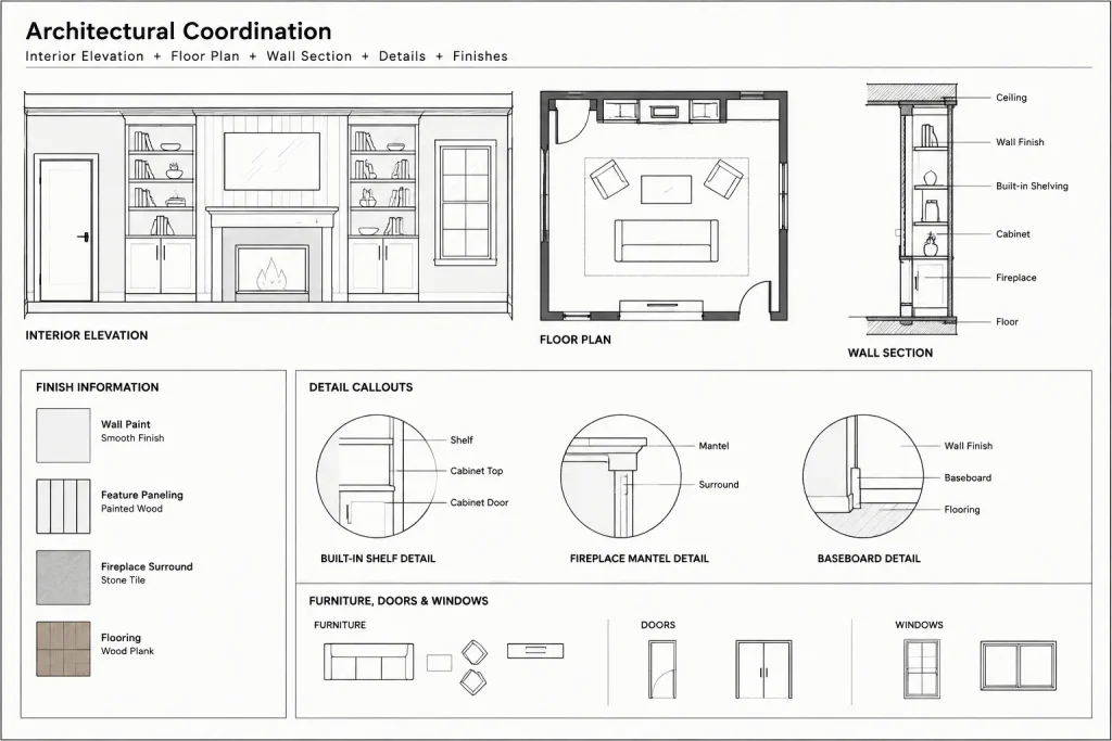
For product-specific items, use verified information supplied for the selected product when available. Generic blocks are useful for planning, but they should not be presented as proof of final size, clearance, connection requirements, or installation suitability.
Connect Elevations to Sections and Details
An elevation shows the face of an assembly, while sections and details explain depth, attachment, edges, and concealed relationships. Add detail references where the elevation alone cannot communicate the construction. Typical examples include countertop edges, cabinet bases, wall panel terminations, recessed items, transitions at openings, and connections to ceilings or floors.
Keep reference callouts specific. The reader should be able to identify what condition the referenced detail explains. After sheets are rearranged or details are moved, confirm that every callout still points to the intended destination.
Manage Revisions Without Losing Coordination
When a room changes, review all of its elevations as a group. A plan revision may affect more than the wall directly edited. Moving a sink, for example, may alter cabinetry, mirrors, lighting relationships, accessories, finish joints, and related notes.
Use a repeatable revision sequence:
- Update the controlling plan geometry.
- Identify every elevation, section, schedule, and detail affected by the change.
- Revise visible geometry before adjusting dimensions and notes.
- Recheck tags and references.
- Plot or preview the affected sheets at their intended output scale.
- Compare the revised views against the plan before marking the change complete.
Interior Elevation Quality-Control Checklist
- Each view matches the room and viewing direction shown on the plan.
- Wall limits, openings, and fixed elements agree with the current floor plan.
- Floor, ceiling, soffit, and opening relationships use coordinated datums.
- Cabinetry, fixtures, equipment, and accessories do not visibly conflict.
- Finish boundaries agree with finish plans, schedules, and related notes.
- Dimensions are necessary, readable, and based on verified geometry.
- Blocks have appropriate units, orientation, detail, and layer behavior.
- Lineweights and patterns remain clear in the plotted sheet.
- View titles, tags, and detail references point to the correct locations.
- Obsolete linework, notes, dimensions, and hidden revisions have been removed.
Make Interior Elevations Part of the Drawing System
The most reliable interior elevations are not standalone illustrations. They are coordinated views within a larger architectural drawing system. Their openings come from the plan, their heights relate to project datums, their finishes connect to schedules, and their construction is clarified by sections and details.
By selecting views deliberately, building from current references, controlling graphic hierarchy, and checking related documents after every meaningful revision, CAD users can produce interior elevations that are easier to read, update, and coordinate throughout the project.
A Practical Review Method Before Issue
A useful final review separates graphic clarity from technical coordination. First, read the elevation by itself and confirm that the wall limits, visible components, annotations, and references are understandable. Then compare it with the controlling plan and related project information rather than relying on the appearance of the elevation alone.
Review the Drawing in Focused Passes
- Location pass: Confirm the room, wall, viewing direction, openings, returns, and adjacent conditions.
- Vertical pass: Compare floor, ceiling, soffit, counter, opening, fixture, and finish relationships against the applicable project datums.
- Component pass: Check cabinetry, equipment, accessories, trim, and repeated elements for omissions or visible conflicts.
- Documentation pass: Verify dimensions, notes, tags, titles, schedule references, and detail callouts.
- Plotting pass: Review line hierarchy, pattern density, text legibility, and the distinction between principal geometry and background information.
This pass-based method helps reviewers find discrepancies that can be missed when geometry, annotation, finishes, and references are checked simultaneously.
Record Unresolved Information Clearly
An interior elevation should not imply that an undecided condition has been fully resolved. When product selection, finish layout, attachment, or consultant coordination remains open, identify the issue through the project’s established review and notation process. Avoid filling gaps with assumed block geometry or copied information from an unrelated condition.
Before issue, confirm which drawing controls each repeated item. A clear source of control reduces conflicts when the same opening, fixture, cabinet, or finish transition appears in several views.
Frequently Asked Questions
What is the difference between an interior elevation and a building section?
An interior elevation looks directly at the visible face of a room wall. A section cuts through the building or assembly to explain depth, concealed construction, and relationships that cannot be shown clearly from the front.
Should every wall in a room receive an interior elevation?
No. Elevations are most useful where vertical relationships, finishes, fixtures, equipment, openings, or custom construction need clarification. A simple wall may already be adequately documented elsewhere in the drawing set.
What information should control the start of an interior elevation?
Begin with current plan geometry and the project’s established datums. Wall limits, openings, returns, fixed elements, ceiling conditions, and related references should be confirmed before detailed surface graphics and annotation are added.
How should downloaded CAD blocks be used in an elevation?
Treat them as reference content until their units, orientation, insertion point, layer behavior, view type, and level of detail have been reviewed. Generic block geometry should not be used as evidence of final product requirements.
How can finish patterns remain readable?
Define finish boundaries before developing joints or patterns, keep finish graphics separate from object outlines, and use restrained linework. Patterns should support the design intent without overpowering fixtures, edges, dimensions, or notes.
What should be checked after a plan revision?
Review every affected elevation along with associated sections, details, schedules, finish information, tags, and references. Update geometry first, then recheck dimensions and annotation against the revised design source.