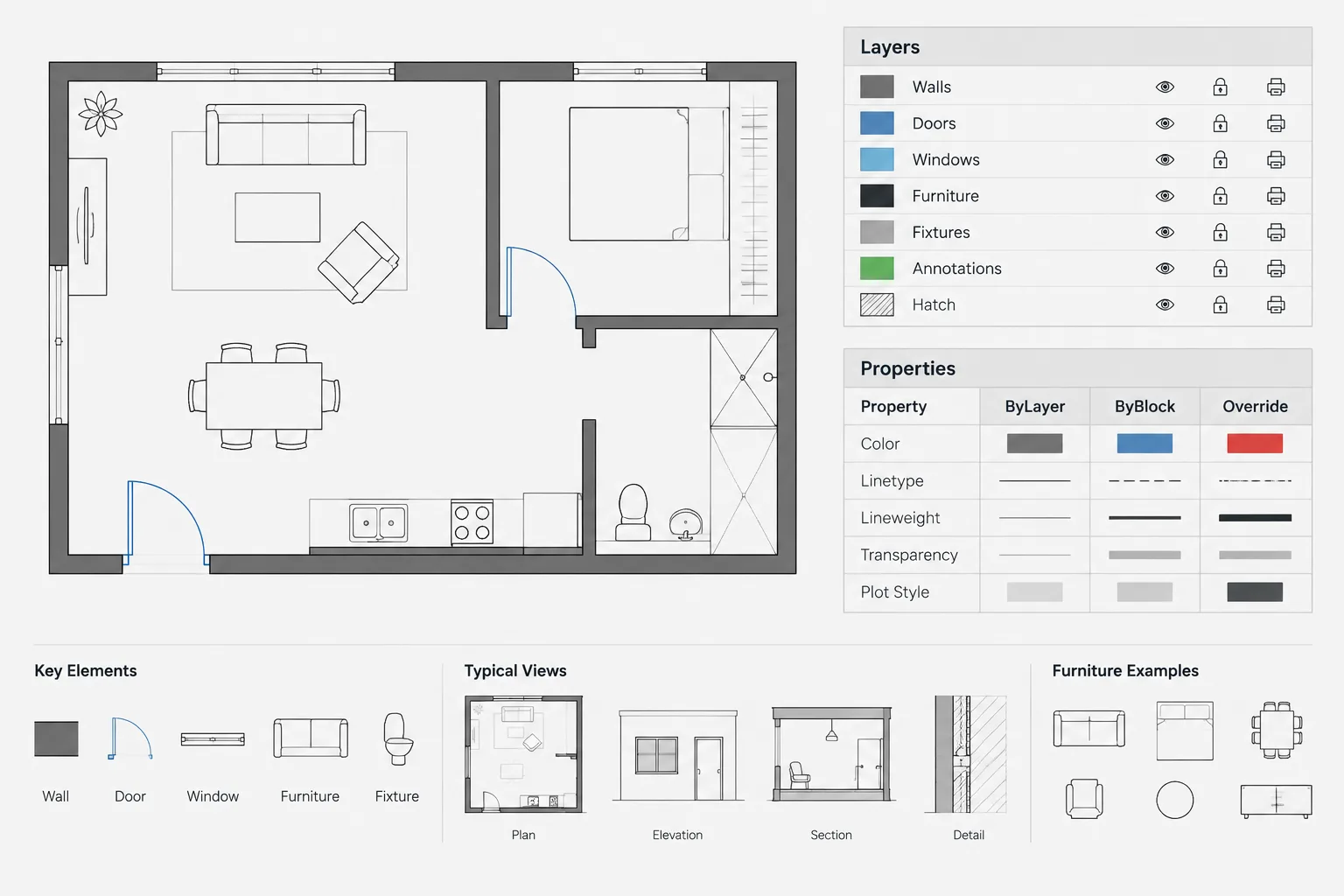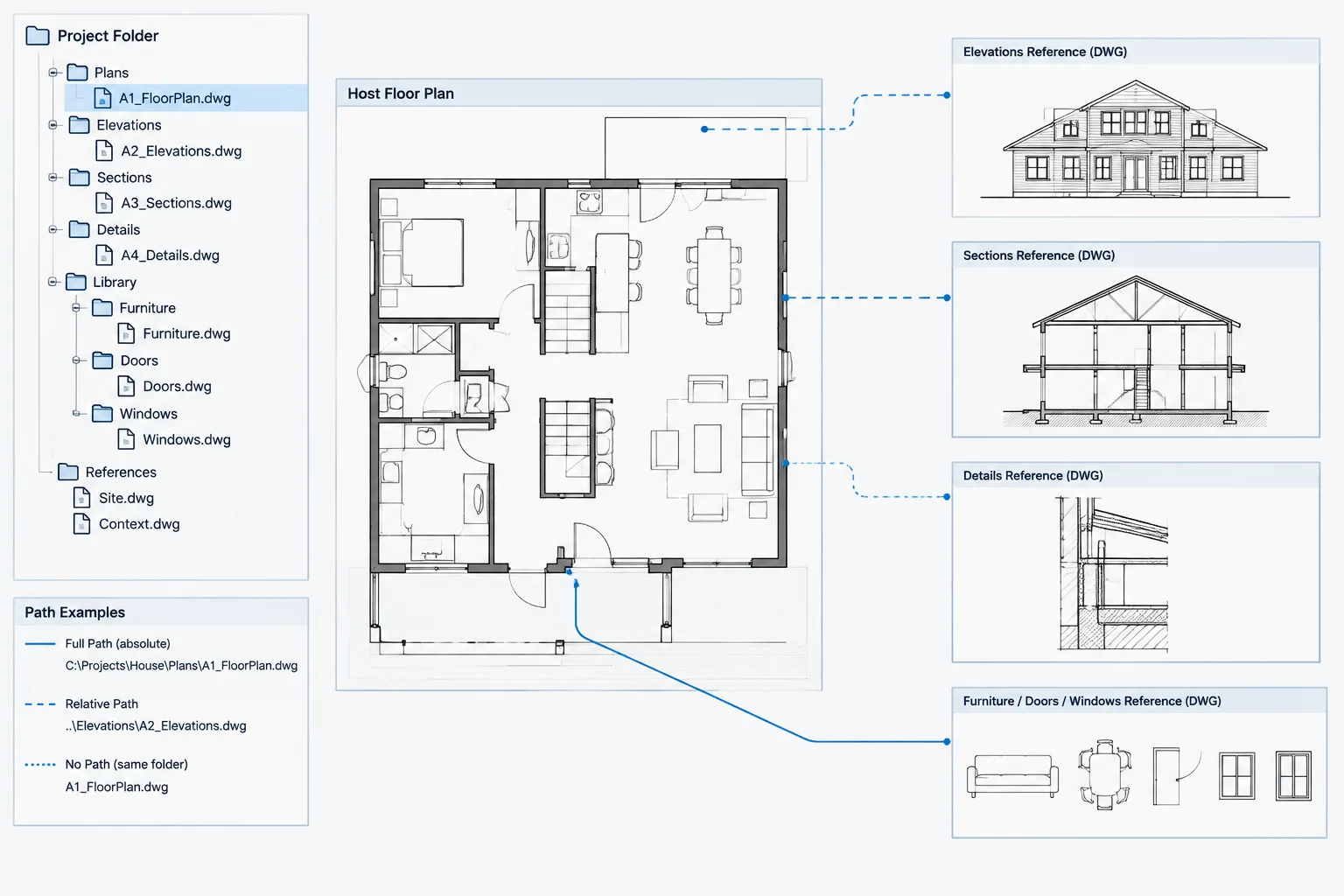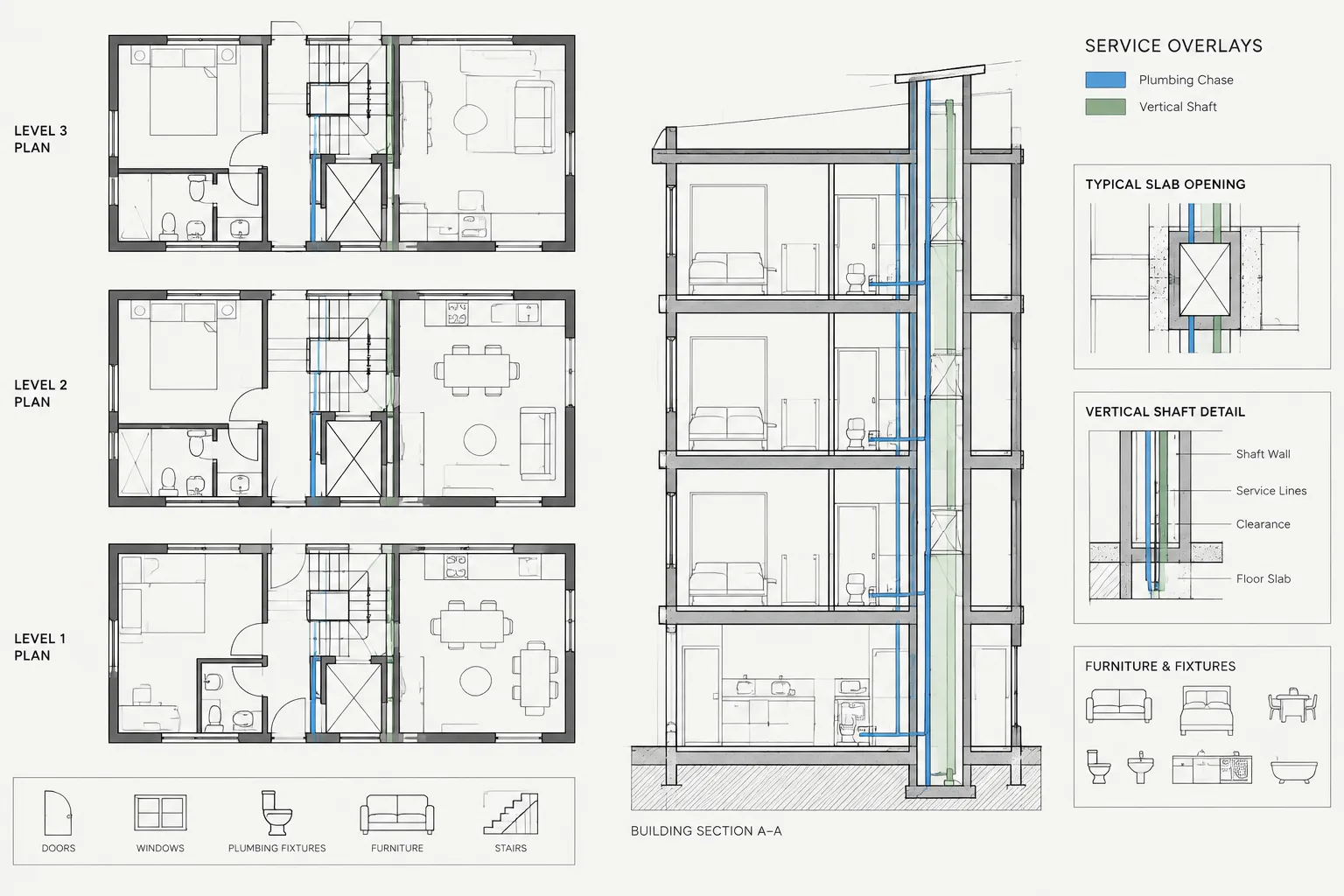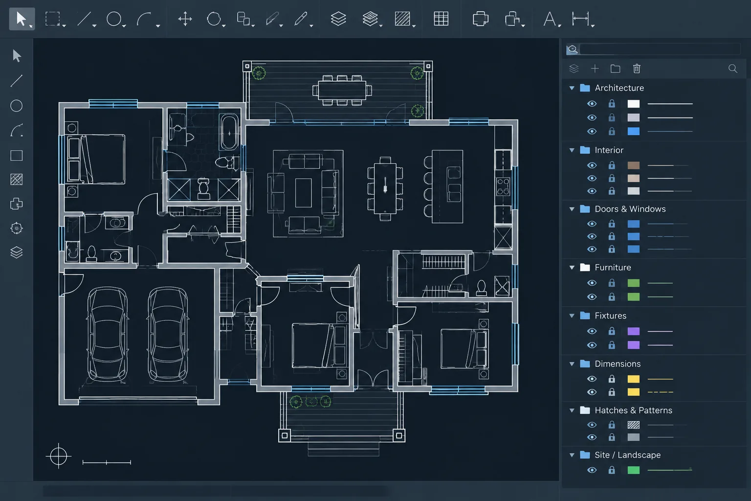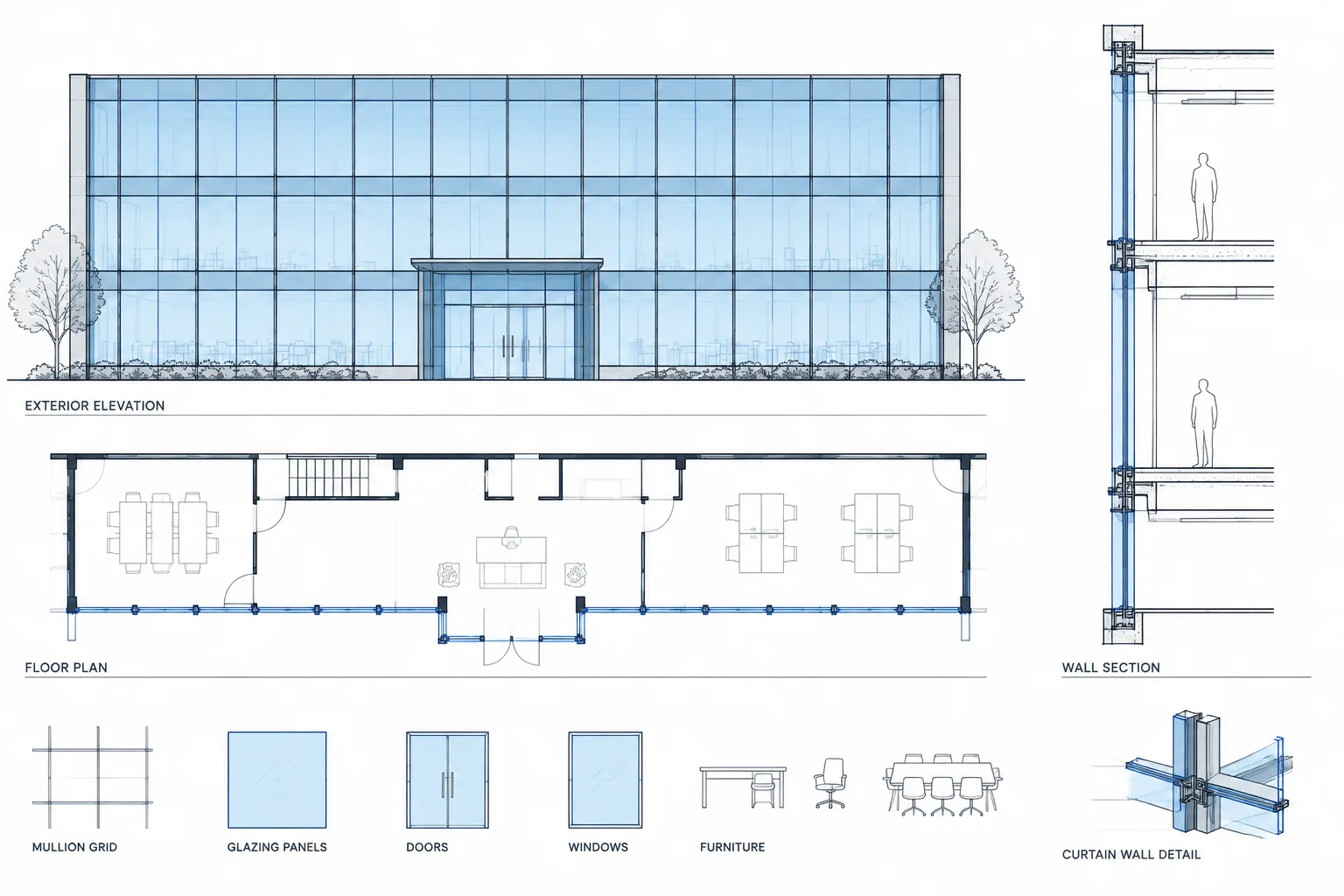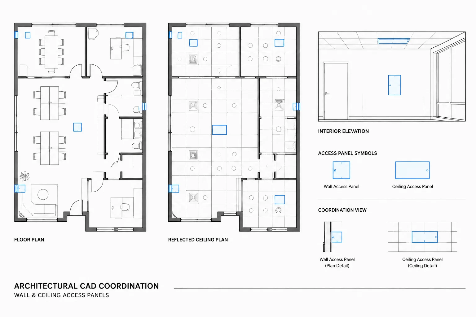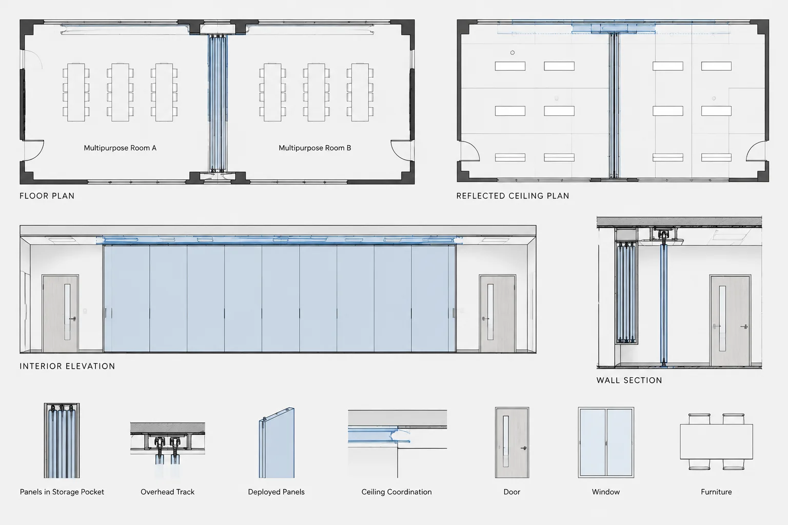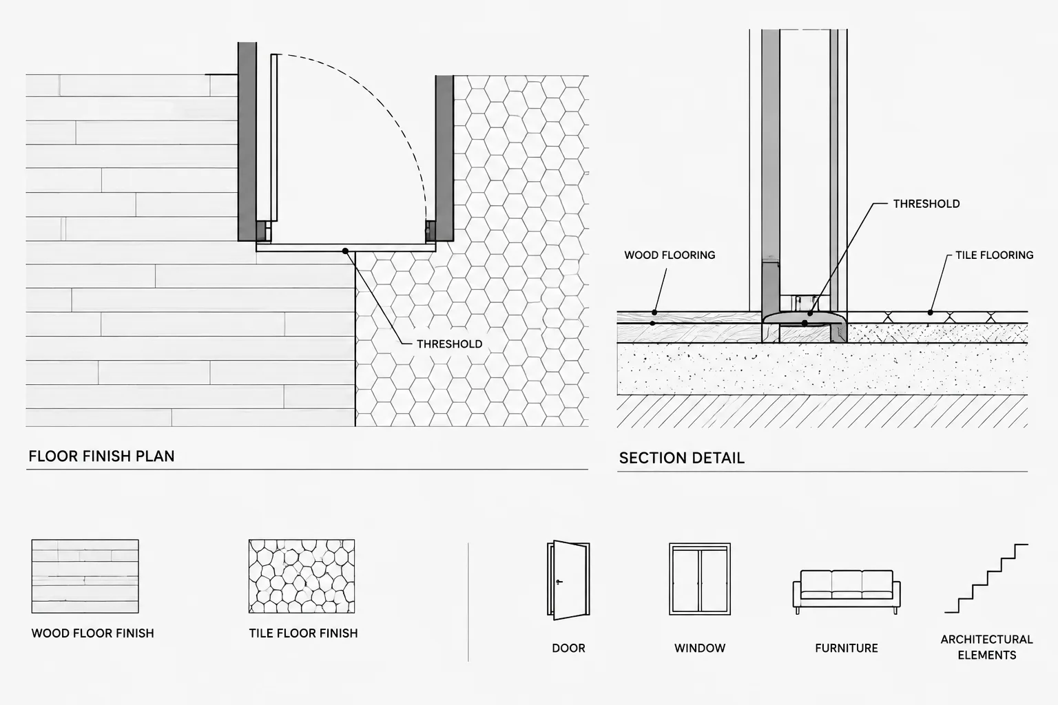
Floor transitions and thresholds require coordination across plan geometry, finish information, openings, and construction details. A clearly drawn boundary tells the project team where a material or assembly changes, while the related annotation explains what that change means.
This guide presents a coordination-first method for drafting these conditions in architectural CAD. It focuses on locating boundaries intentionally, separating linework from finish hatches, connecting plans with schedules and details, and reviewing conditions that cannot be resolved through a generic symbol alone.
Floor transitions are small drawing elements with wide coordination consequences. A boundary between carpet and resilient flooring may affect the finish plan, door location, substrate preparation, accessibility, interior elevations, specifications, and construction details. At exterior doors, a threshold may also interact with drainage, weather protection, and the building envelope.
A reliable CAD workflow does more than draw a line between two hatch patterns. It establishes where the transition occurs, identifies what changes across it, and connects the plan information to the detail or product selection needed for construction. The following process explains how to represent floor transitions and thresholds clearly without overloading the drawings.
Start by Classifying the Transition
Before drafting, determine what kind of condition the line represents. This prevents one generic symbol from being used for situations that require different coordination.
- Finish-only transition: Two finishes meet while the supporting floor remains at the same general level.
- Profile transition: A strip, reducer, edge profile, or similar component covers or protects the finish junction.
- Substrate transition: The finish change also requires a change in underlayment, setting bed, topping, or floor preparation.
- Level change: The adjacent finished surfaces are not intended to align.
- Door threshold: The transition is coordinated with a door frame, door leaf, hardware, or exterior opening.
- Movement or separation condition: The finish boundary aligns with a joint or another assembly break that must remain coordinated through multiple materials.
These categories do not replace project specifications or manufacturer information. They help the CAD drafter recognize when a simple finish boundary is insufficient and a detail reference is needed.
Establish the Intended Transition Location
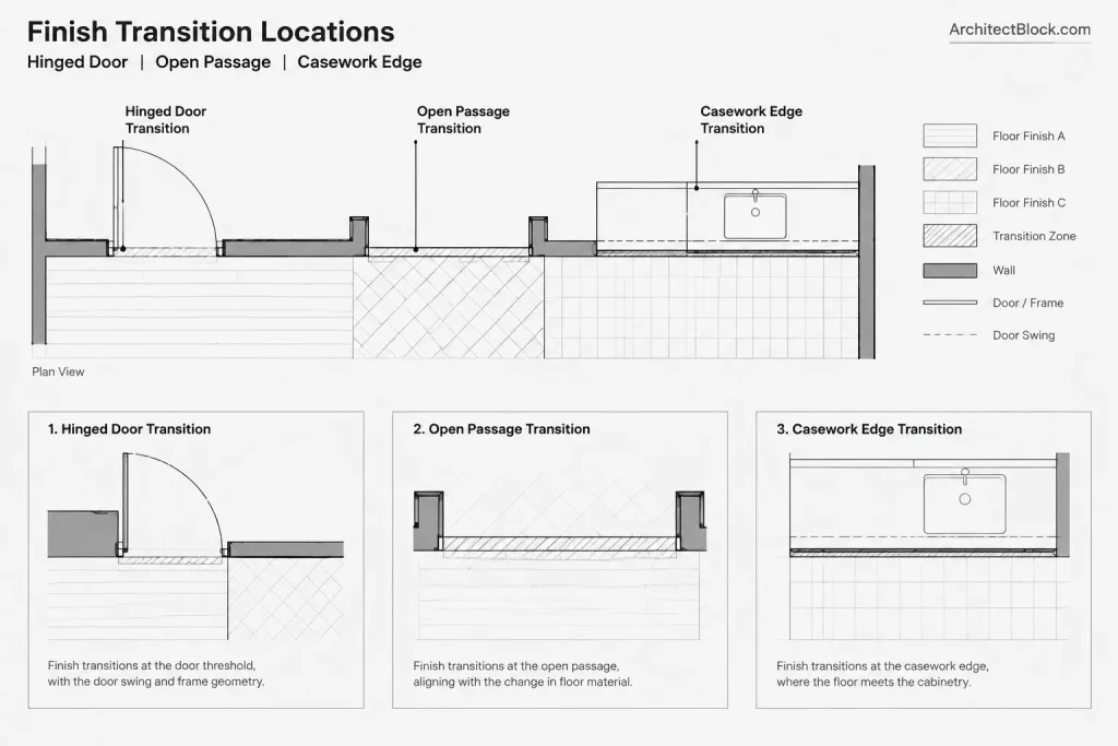
A finish boundary should be located by design intent rather than by the convenient edge of a hatch. Common controlling references include the centerline of a closed door, a frame face, a wall finish face, a casework edge, a room boundary, or a documented joint location.
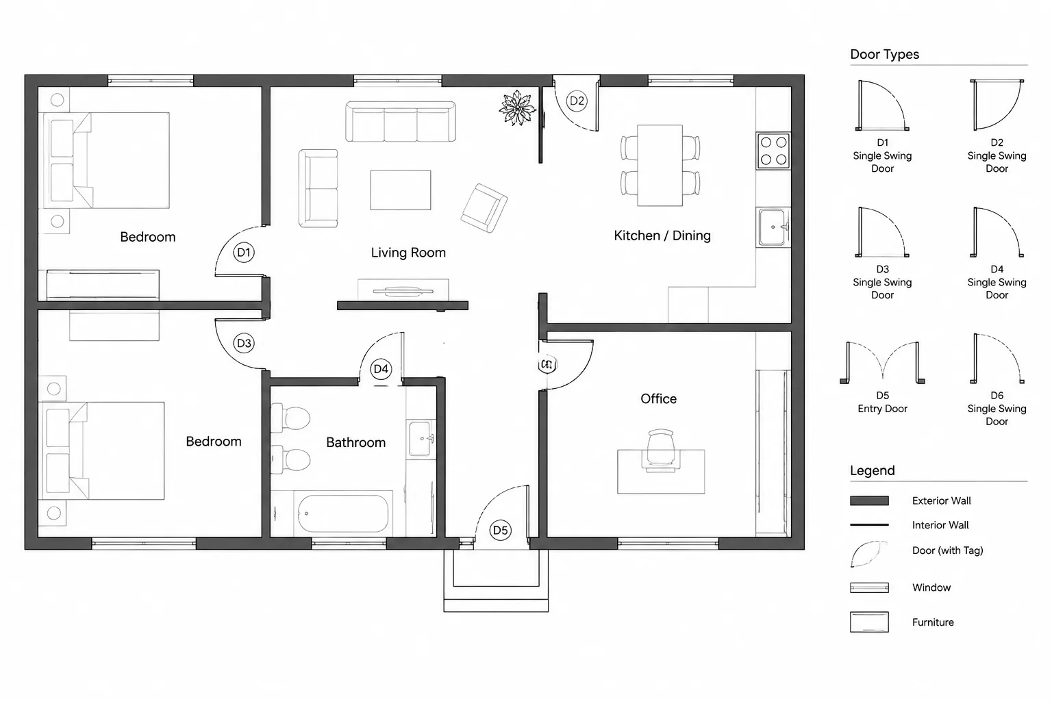
At doorways, inspect the door swing and determine which finish should be visible when the door is closed. The answer may vary with frame configuration, door undercut, threshold type, and the direction from which the opening is viewed. Avoid automatically placing every transition at the wall centerline.
For open passages without doors, the transition may align with an architectural edge such as a wall return or opening face. In large open rooms, a finish boundary may instead follow a deliberate pattern, ceiling feature, furniture zone, or circulation route. Those relationships should be checked rather than inferred from room names alone.
Choose the Drawing That Controls the Information
The same transition can appear in several views, but one drawing should serve as the primary location for each type of information. This limits conflicting notes and duplicate dimensions.
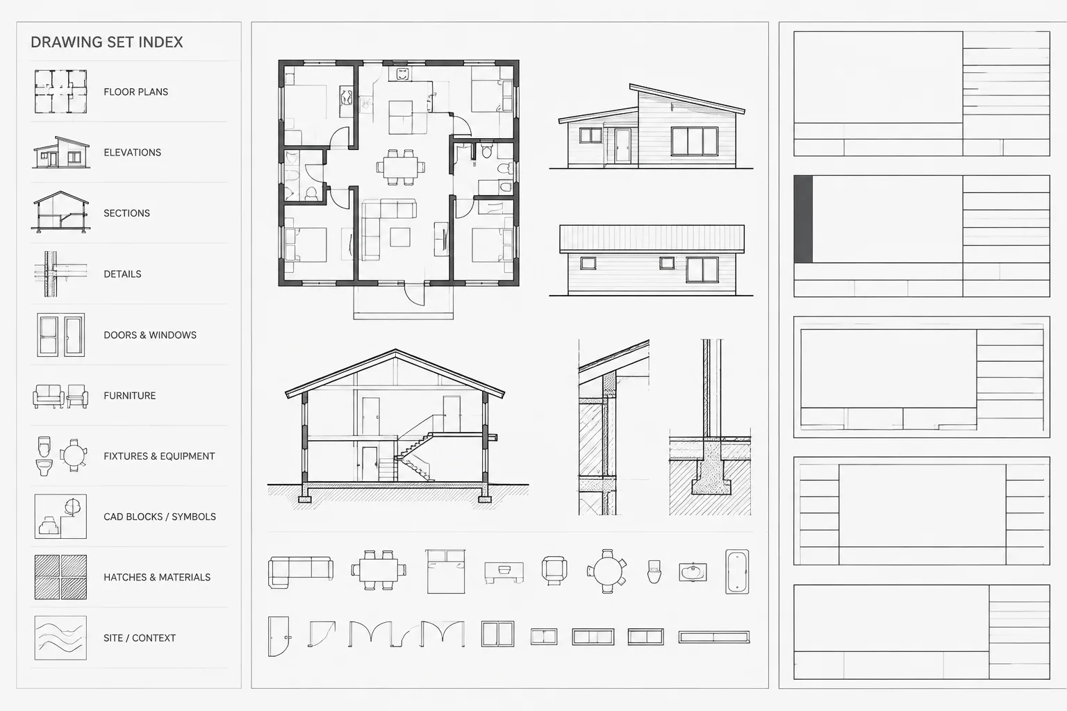
| Drawing or document | Useful information to show | Common coordination risk |
|---|---|---|
| Floor finish plan | Finish extents, transition lines, finish tags, and key references | Boundary does not match the actual doorway or room geometry |
| Enlarged plan | Precise relationship to frames, walls, casework, and fixtures | Enlarged geometry drifts from the overall plan |
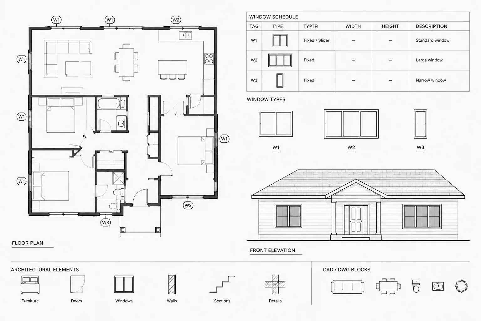
| Door schedule or opening information | Threshold requirement or reference associated with an opening | Plan indicates a threshold that is missing from the opening data |
| Interior elevation or section | Vertical relationship, visible profile, and adjacent assembly | Finish thicknesses conflict with the plan or detail |
| Transition detail | Assembly concept, profile orientation, substrates, and sealant or joint relationships | Generic detail is used for a condition it does not represent |
| Finish schedule or specifications | Finish identity, transition product description, and selection criteria | Abbreviations or material names differ from plan tags |
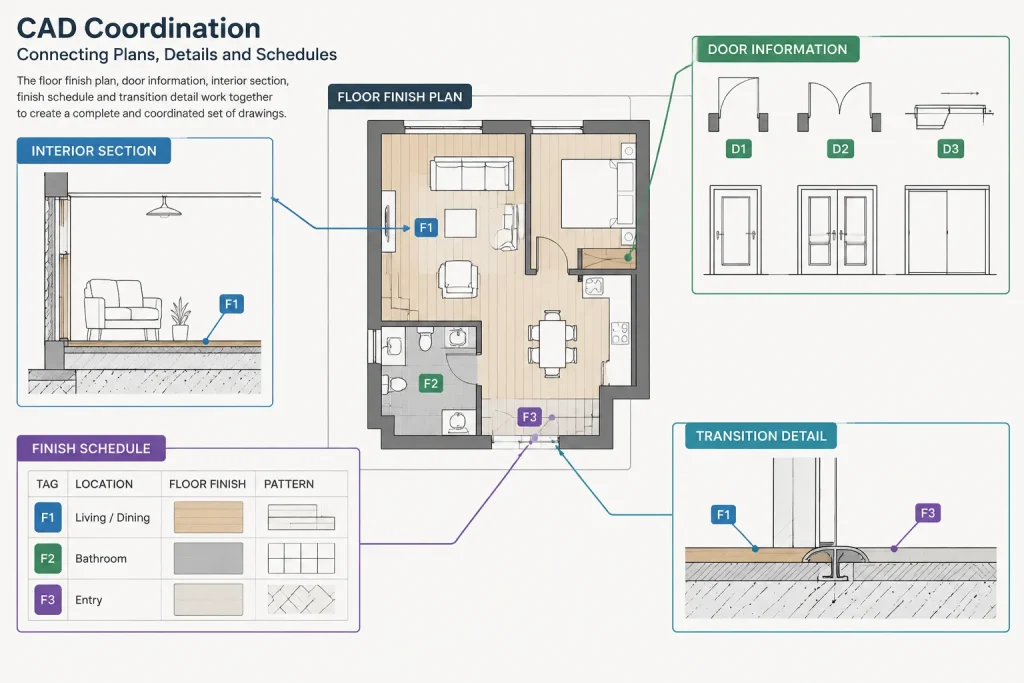
A practical division of responsibility is to use the finish plan for location and identification, then use a detail for assembly and vertical relationships. Product-specific requirements should be verified against current project information rather than reconstructed from a generic CAD block.
Draft the Plan Symbol Clearly
Use a dedicated boundary object
Draw the finish boundary as intentional CAD geometry instead of relying only on adjacent hatch edges. A separate line or polyline is easier to select, revise, layer, and compare against the architectural plan. It also remains visible when hatch display or plotting changes.
Keep the boundary continuous through the relevant opening, but trim it where another graphic convention should take precedence. The line should not create a false wall edge or appear heavier than nearby cut construction.
Separate graphic roles by layer
Transition boundaries, finish hatches, finish tags, and detail callouts perform different functions and should be controllable independently. A project layer structure may separate them so that each can receive an appropriate linetype, color, lineweight, and viewport treatment.
Use project naming conventions rather than creating an isolated layer name for one detail. Object properties should normally follow the established layer strategy unless the project has a documented reason for an override.
Use restrained annotation
Not every finish boundary needs a long note. Where the finish plan already identifies both adjoining materials, a transition tag or detail reference may be enough. Add a specific note when the location, orientation, or condition would otherwise remain ambiguous.
Place leaders so they point to the actual transition rather than to a nearby hatch field. If several identical conditions occur, use a repeatable tag system and verify that every tagged instance truly matches the referenced detail.
Coordinate Hatches Without Letting Them Control Geometry
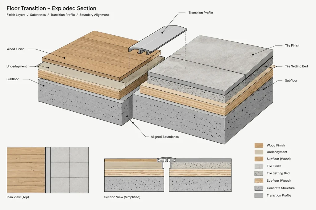
Finish hatches communicate material zones, but they should follow the approved boundary geometry rather than define it. Create or update closed boundaries first, then apply or regenerate the hatch. This reduces slivers, overlaps, and inconsistent edges around door frames.
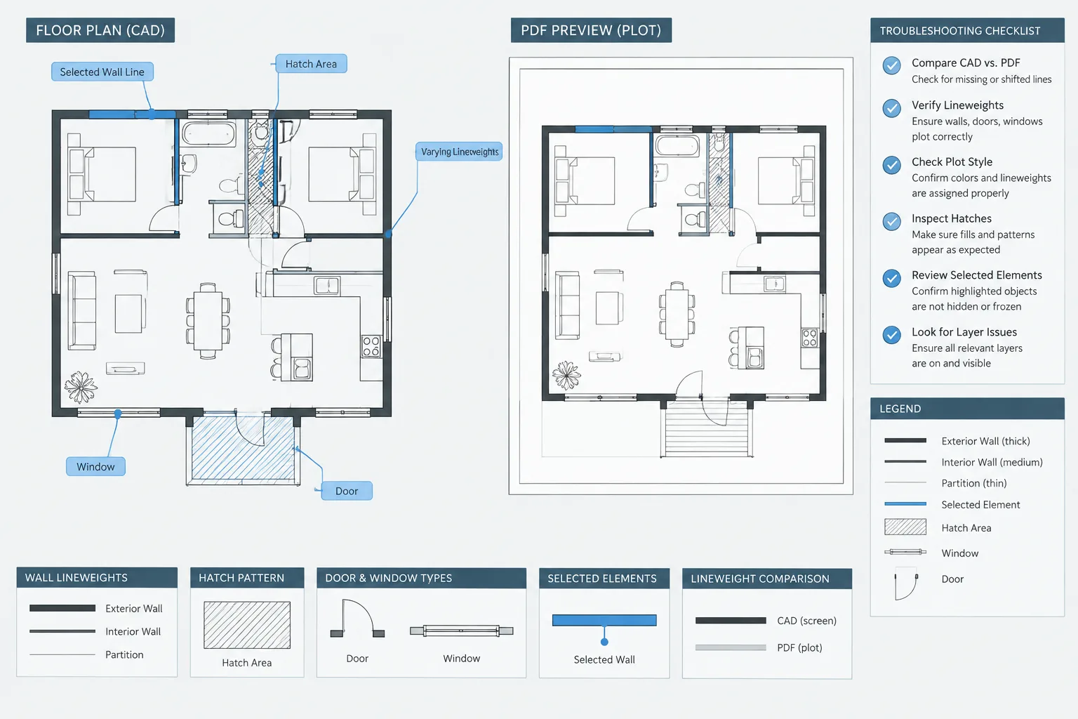
Check transitions at a useful zoom level as well as at plotted sheet scale. A tiny CAD gap may allow a hatch to leak into another room, while an excessive overlap can conceal the transition line. Dense patterns may also merge visually when reduced, so prioritize a readable distinction over decorative detail.
Where a finish pattern has a meaningful direction, origin, or module, coordinate it separately from the transition line. A boundary may be correct even when the pattern alignment is not, and the two issues should not be confused during review.
Develop Threshold and Transition Details
A detail should explain the condition that cannot be understood from the plan alone. Show only the adjacent construction needed to communicate the relationship. Depending on the project, this may include finish layers, supporting materials, a transition profile, the door and frame relationship, sealant, a joint, or an exterior drainage interface.
Organize detail geometry by material and depth. Elements cut in section should read more strongly than surfaces seen beyond. Avoid filling a small detail with excessive hatch density or manufacturer-like geometry that has not been verified.
If a proprietary profile is under consideration, use a simplified placeholder and clearly distinguish design intent from final product selection. Do not treat a downloaded detail or block as project-ready without checking its dimensions, materials, installation requirements, and compatibility with the surrounding assembly.
Check Vertical Coordination
Two finish surfaces that appear flush in plan may have different assembly thicknesses. Coordinate the transition with the structural or base floor, underlayments, waterproofing, setting materials, floor recesses, and adjacent room requirements.
Where the transition involves a change in elevation, the drawings should communicate the intended vertical relationship in an appropriate section or detail. Accessibility, tripping hazards, door operation, weather protection, and code implications must be reviewed against the applicable project criteria and jurisdiction. Do not assume that a generic reducer or threshold resolves those issues.
Use Reusable Blocks Carefully
A simple transition tag can work well as a block, especially when it includes editable fields or attributes for a type designation and detail reference. Keep the graphical marker simple and readable in every planned sheet context.
Avoid embedding the finish boundary itself inside a repeated tag block. The boundary length and geometry are usually condition-specific and are easier to coordinate as normal linework. Likewise, detailed threshold profiles should not be inserted blindly at every door; orientation and adjacent assemblies can differ.
Quality-Control Checklist
- Confirm that every transition line represents a real change in finish or assembly.
- Verify the line location against walls, door frames, casework, and opening geometry.
- Check which finish is intended to appear beneath a closed door.
- Compare finish plan tags with the finish schedule and material legend.
- Confirm that threshold references agree with door or opening information.
- Review substrate and finish thickness changes in section.
- Check hatch boundaries for gaps, overlaps, and unintended islands.
- Make sure transition markers remain legible at the plotted sheet scale.
- Verify that repeated detail references apply to every referenced condition.
- Review exterior thresholds with envelope, drainage, and door coordination information.
- Remove obsolete transition lines after room layouts or finish selections change.
A Coordination-First Drafting Sequence
A dependable workflow begins with the current architectural base plan. Confirm room and opening geometry, establish finish zones with closed boundaries, and place transition lines at their intended construction references. Apply hatches only after those boundaries are stable. Then add finish tags, transition identifiers, and detail callouts.
Next, compare the plan against door information, interior elevations, sections, and finish documentation. Develop only the details needed to explain distinct conditions, and keep generic placeholders visibly separate from verified product information. Before issue, plot the sheets and inspect both the overall graphic hierarchy and the doorway-level coordination.
Well-coordinated floor transitions are rarely the most prominent part of an architectural drawing set, but they reveal whether plans, schedules, openings, and details have been developed as one system. Precise boundary geometry and disciplined cross-checking can prevent a small line in CAD from becoming a large field question.
Managing Transition Information Through Revisions
Floor transition coordination should continue after the initial finish plan is drafted. Door locations, frame configurations, room layouts, casework, finish selections, and substrate requirements can all change while the drawing set develops. A transition line that was once correct may remain in the file even after its controlling geometry has moved.
During each drawing review, compare transition geometry with the current architectural base rather than checking only whether the line still appears on the sheet. CAD overlays or other comparison methods can help reveal shifted openings, duplicate boundaries, abandoned hatch edges, and detail references that no longer match the plan.
Track recurring conditions by intent
Where a project uses repeated transition types, assign identifiers according to the actual assembly concept rather than visual similarity alone. Conditions that look alike in plan may differ because of substrates, door relationships, moisture exposure, movement joints, or exterior interfaces.
A simple transition register can help the project team compare each identifier with its location, adjacent finishes, opening information, and referenced detail. This is especially useful when a finish designation changes but the transition component or assembly still requires separate review.
Distinguish confirmed information from placeholders
Early drawings may need to communicate design intent before a final profile or product has been selected. Use simplified geometry and clear notes so preliminary information is not mistaken for verified fabrication or installation data. Replace or revise placeholders when coordinated project information becomes available.
Review the plotted result
Model-space accuracy does not guarantee sheet clarity. Inspect plotted views for hatch interference, competing lineweights, crowded leaders, clipped tags, and transition lines concealed by door or frame graphics. The final test is whether a reader can identify the location, understand the adjoining finishes, and find the supporting information without guessing.
Frequently Asked Questions
Where should a floor transition line be placed at a doorway?
Place it according to the intended relationship among the finishes, door, frame, and wall surfaces. Check which finish should be visible when the door is closed rather than automatically using the wall centerline.
Should every finish change have a threshold detail?
No. A straightforward finish boundary may be adequately described by the finish plan and schedule. Add a detail when the vertical assembly, profile, substrate, joint, door relationship, or exterior interface cannot be understood from the plan alone.
Can hatch edges serve as transition lines?
Hatches should follow the transition geometry, not replace it. A dedicated line or polyline is easier to revise, control by layer, compare with the base plan, and keep visible when hatch display changes.
Should a threshold profile be stored as a reusable CAD block?
A simplified tag or reference marker may be reusable, but detailed profile geometry should be checked for each condition. Orientation, adjoining materials, substrates, and opening assemblies can vary even when conditions appear similar in plan.
What should be checked at an exterior threshold?
Coordinate the opening with the door and frame, finish levels, surrounding floor assembly, drainage approach, weather-protection strategy, and building-envelope information. Applicable accessibility and code criteria require project-specific professional review.
How can transition errors be found before a drawing issue?
Compare the finish plan with the current architectural base, opening information, schedules, sections, and details. Then review the plotted sheets for displaced boundaries, conflicting tags, hatch gaps, obsolete references, and unreadable graphics.