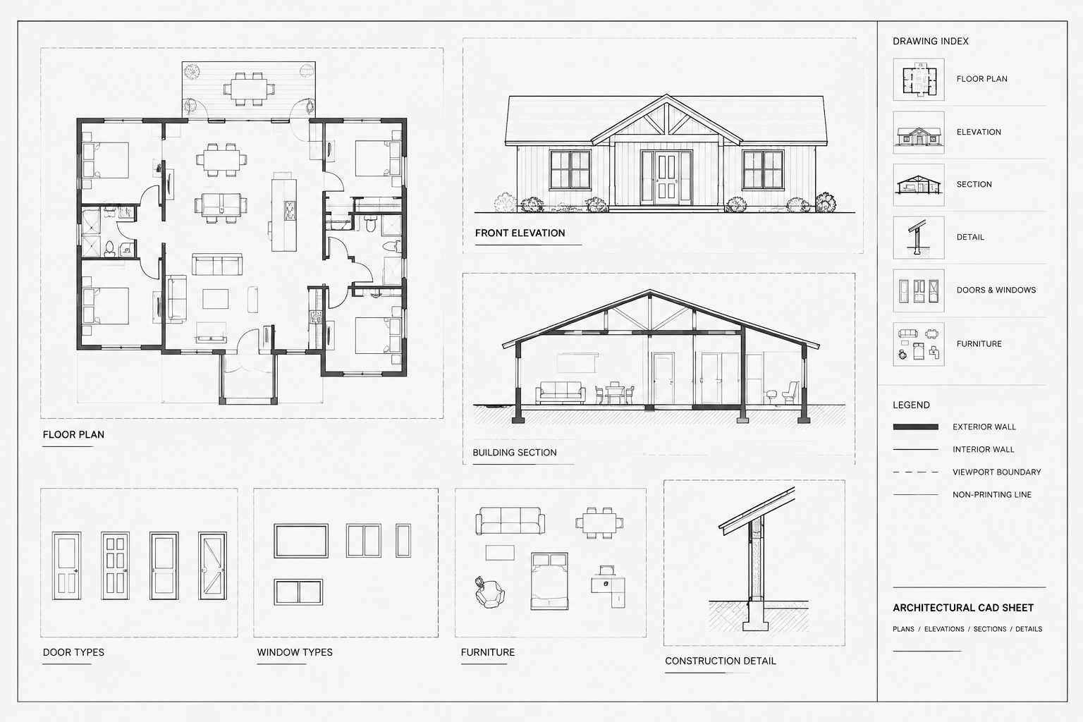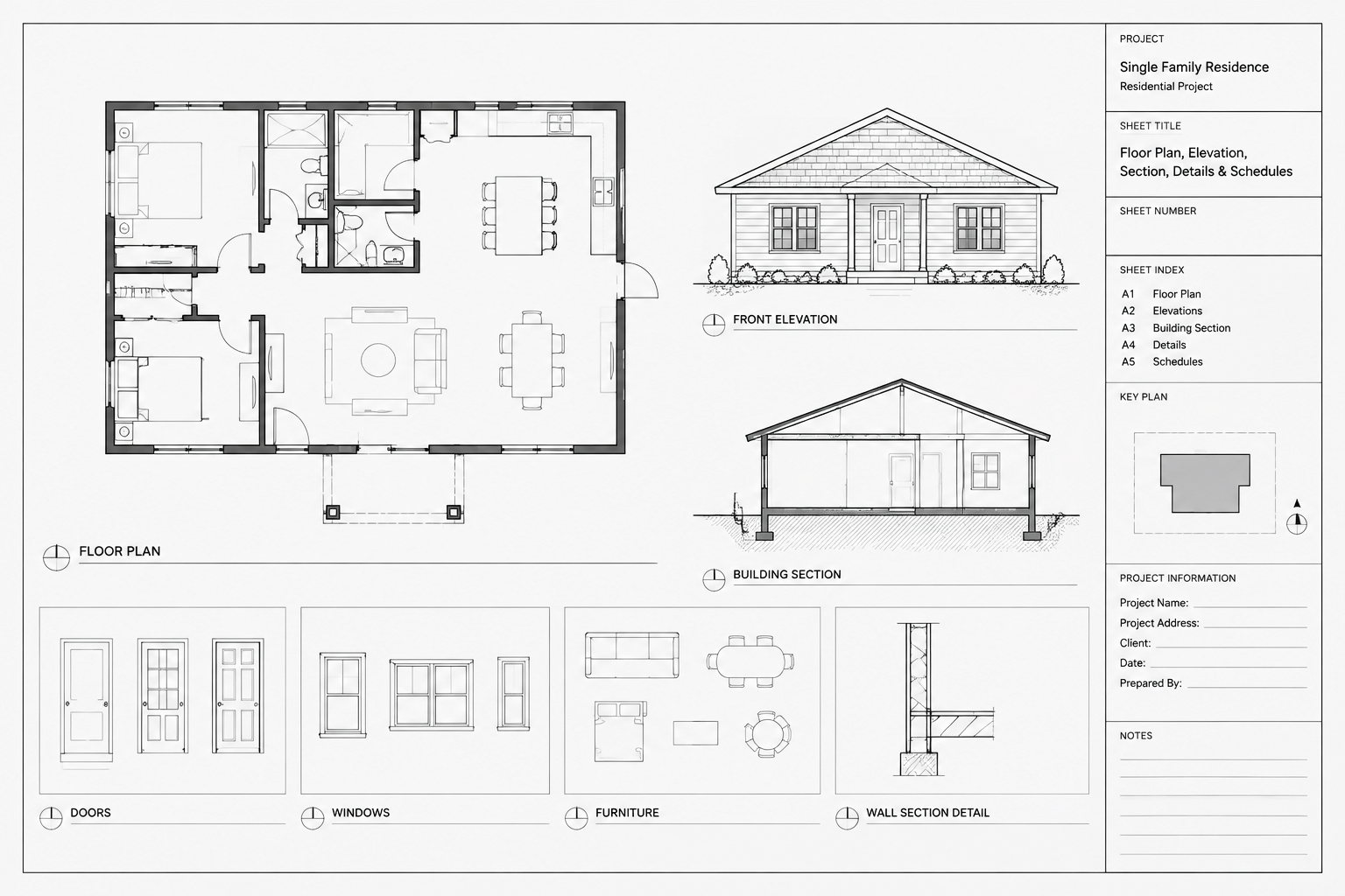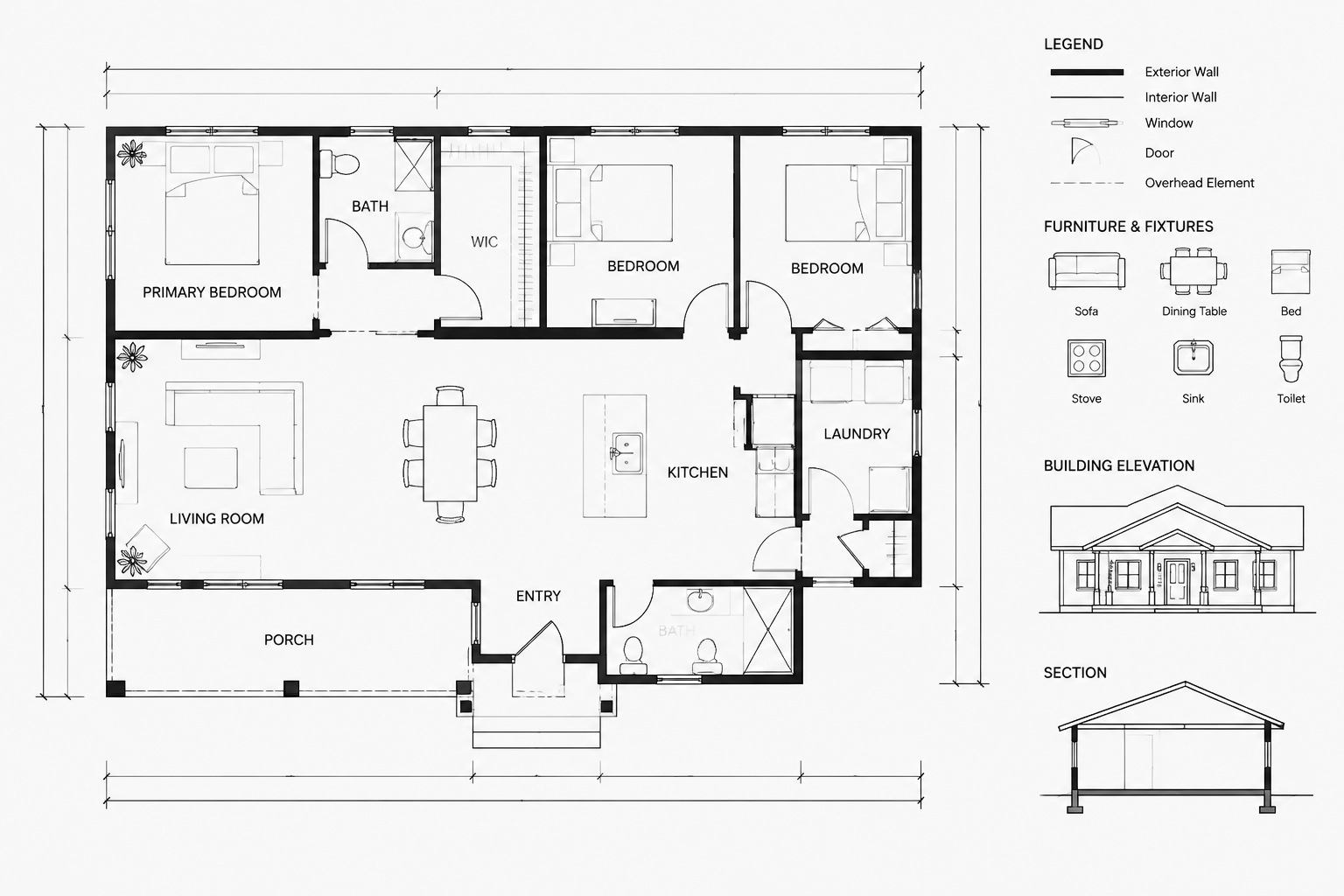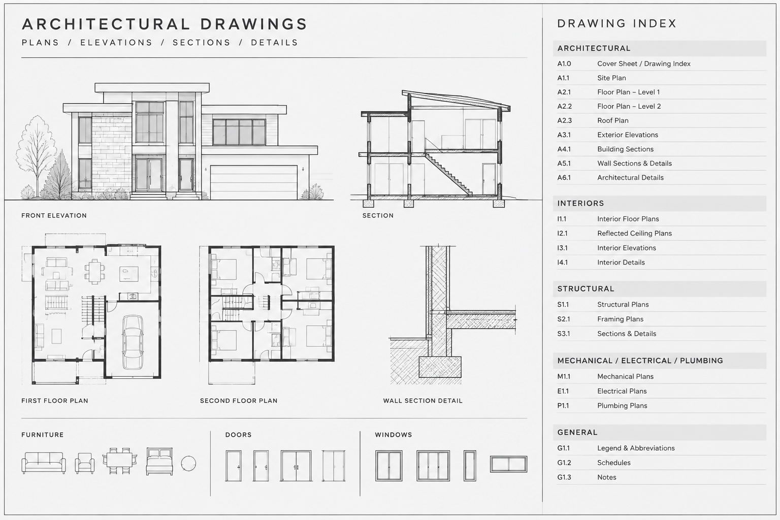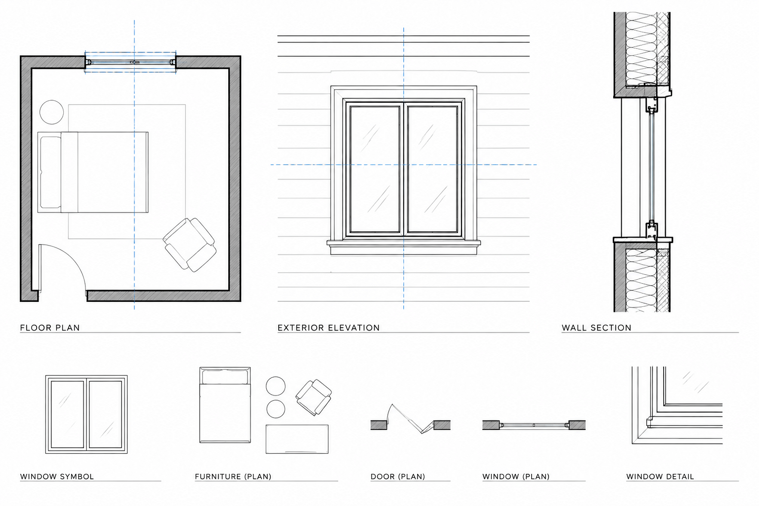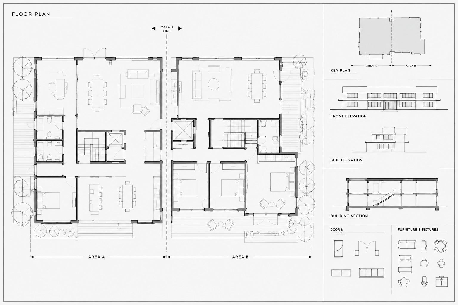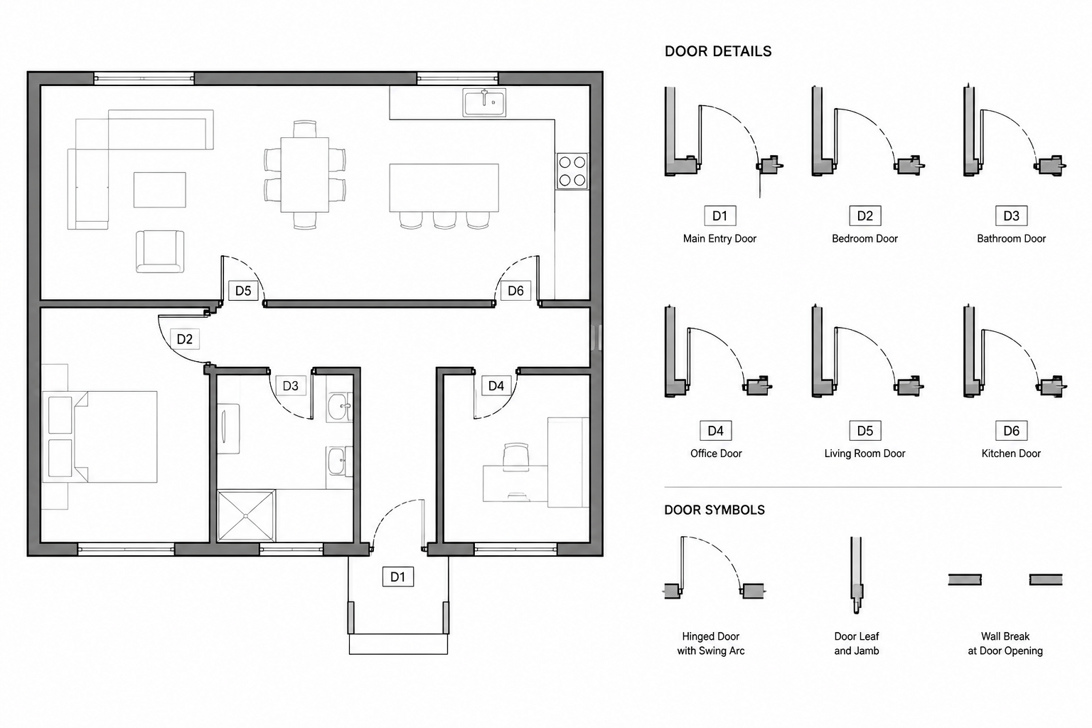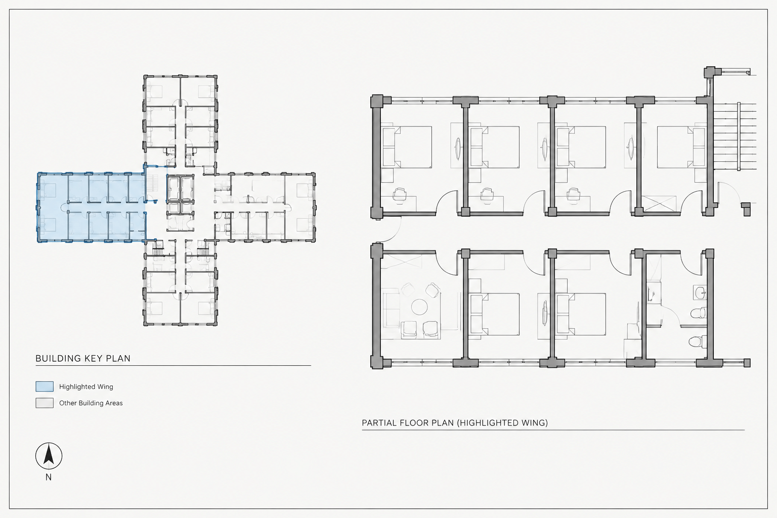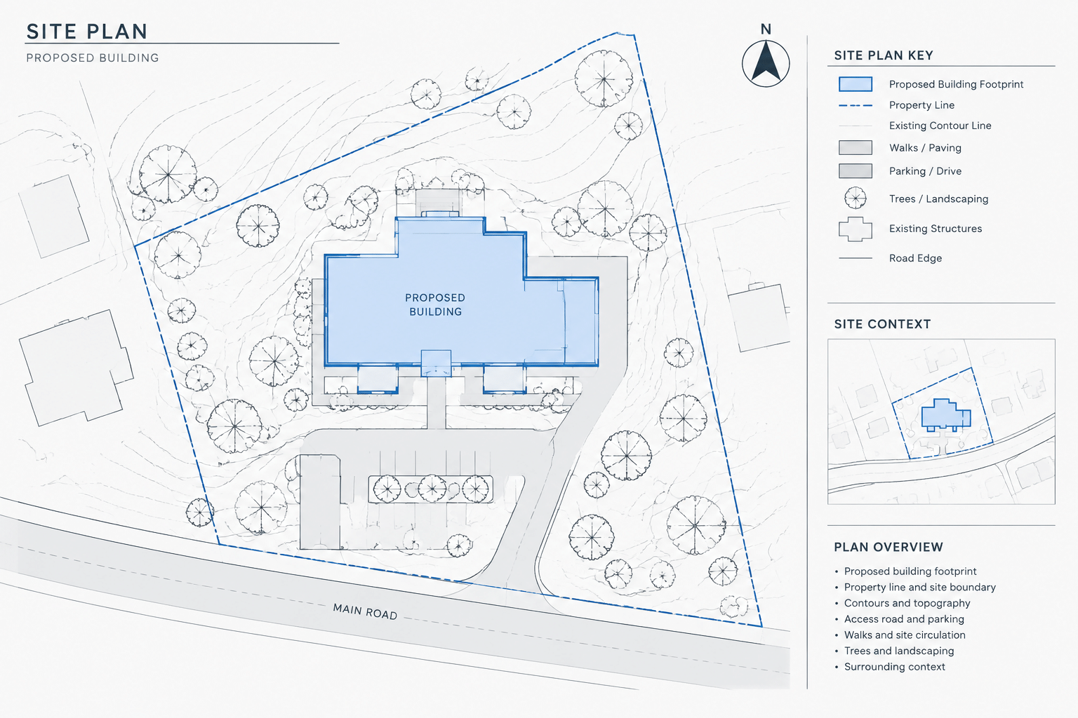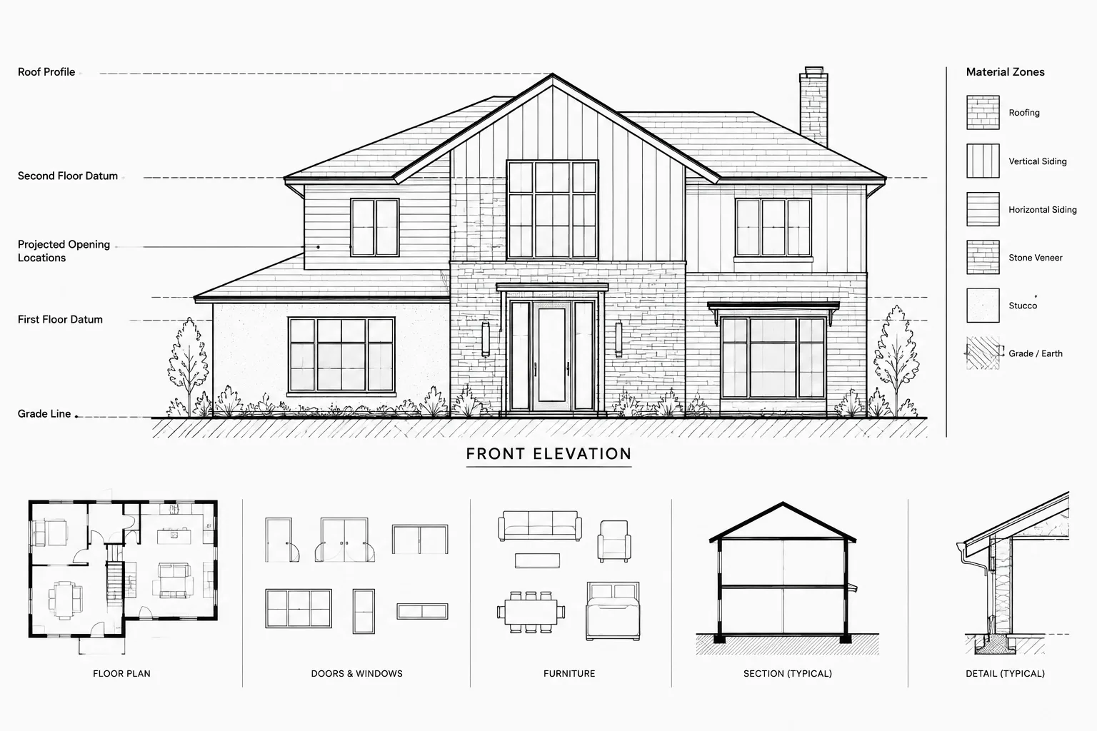
Exterior building elevations communicate the vertical appearance of a project: openings, materials, roof forms, grade relationships, architectural features, and visible equipment. Although an elevation may begin as a projection from the floor plan, it should not be treated as an isolated drawing. It must remain coordinated with plans, sections, schedules, details, and the current design model or reference files.
A reliable CAD workflow separates project geometry from graphic presentation. The building should be projected accurately first, followed by materials, annotations, dimensions, and sheet-specific linework. This approach makes changes easier to track and reduces the risk of an elevation looking finished while no longer matching the rest of the drawing set.
What an exterior elevation needs to communicate
An exterior elevation is an orthographic view rather than a perspective. Elements are shown on a flat vertical plane, allowing the design team to compare heights, align openings, identify exterior finishes, and locate major architectural features.
Depending on project scope and drawing phase, an elevation may show:
- Exterior walls, foundations, parapets, eaves, and roof edges
- Doors, windows, storefronts, louvers, and other openings
- Balconies, canopies, stairs, railings, columns, and projections
- Finish changes, joints, panels, masonry patterns, and trim
- Finished grade and significant site relationships
- Level markers, vertical dimensions, material tags, and notes
- Visible exterior fixtures, vents, equipment, or screening
- Elevation titles and references to related details or sections
The exact content should follow the project’s documentation requirements. Avoid adding generic notes or assumed construction information that has not been confirmed by the design team.
Prepare the CAD references before drafting
Begin with the latest coordinated floor plans, roof plan, and relevant building sections. If the project uses external references, attach those files using the office’s established origin, path, and naming practices. Keep referenced geometry on its source layers instead of tracing everything into the elevation file without a clear reason.
Review the plan before projection. Confirm which façade is being drawn, which parts of the building are visible, and whether recessed or projecting elements overlap in the view. Check floor levels, roof geometry, opening locations, wall offsets, and exterior features. A plan that contains unresolved geometry will produce an equally unresolved elevation.
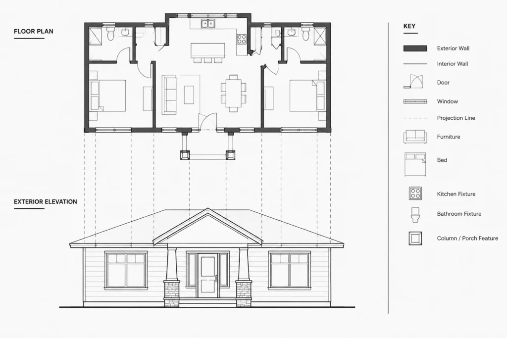
Establish common control geometry
Create or reference horizontal level datums for the important vertical positions used by the project. These may include floor levels, roof lines, parapets, ceiling-related features, and other controlling heights. Use the same project information that supports the sections rather than estimating positions from a printed view.
Project vertical construction lines from major plan locations, including:
- Building corners and wall changes
- Door and window openings
- Structural or architectural grids when relevant
- Columns, bays, recesses, and projections
- Roof edges, canopies, balconies, and exterior stairs
- Material transitions controlled by plan geometry
Place temporary projection lines on a dedicated non-plot layer or another clearly managed construction layer. They should remain easy to hide, freeze, or remove after the elevation geometry has been verified.
Build the elevation from large forms to small details
Draft the overall silhouette first. Establish the visible grade line, exterior wall boundaries, roof profile, parapets, and major projections. Next, add openings and major architectural features. Finish with material patterns, joints, trim, fixtures, and annotation.
This sequence prevents decorative linework from hiding basic coordination errors. It also makes revisions more manageable because the primary geometry can be checked before time is spent on finish representation.
Project doors and windows carefully
Opening widths and horizontal positions should come from the plan. Head, sill, and threshold positions should come from coordinated vertical information, such as sections, schedules, or approved design criteria. Do not infer missing heights from the appearance of a downloaded CAD block.
Elevation blocks for doors and windows can improve drafting speed, but they must match the scheduled type and actual opening configuration. Check frame divisions, operable panels, mullions, transoms, and visible trim. Simplify components appropriately for the plotted scale; excessive block detail can make the façade harder to read.
Resolve depth and overlapping elements
A flat elevation still needs to communicate depth. Use lineweight and selective linework to distinguish the primary façade plane from recessed walls, projecting canopies, foreground columns, and elements beyond. Hidden geometry should only be shown when it serves a clear documentation purpose and follows the project’s drawing conventions.
Where a projection hides part of the wall, trim or mask the concealed linework instead of allowing every edge to run through. The result should explain which elements are in front without imitating a rendered image.
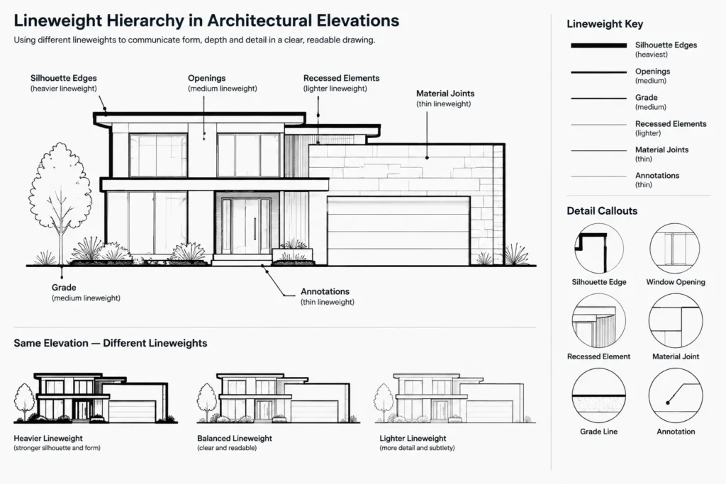
Create a readable elevation lineweight hierarchy
Lineweight should describe form before material. The outer silhouette and significant cut or foreground edges generally need stronger emphasis than surface joints and finish patterns. Fine lines can then describe secondary components without competing with the building outline.
| Drawing information | Suggested graphic treatment | Coordination concern |
|---|---|---|
| Building silhouette and major foreground edges | Strong, continuous emphasis | Confirm roof, wall, and grade relationships |
| Openings and major architectural features | Clear medium emphasis | Match plans, schedules, and sections |
| Recessed or background elements | Lighter linework | Confirm what is actually visible |
| Material joints and surface patterns | Fine, controlled linework | Align with finish intent and details |
| Annotations and markers | Consistent plotted text and symbols | Coordinate references and terminology |
| Projection and construction lines | Non-plot or temporary treatment | Remove or hide before issue |
Always test the hierarchy at the intended plotted output. A façade that looks clear while zoomed in may become dense or visually flat on the sheet.
Represent materials without overwhelming the drawing
Material graphics should help identify finish zones and changes in plane. Use hatches, line patterns, outlines, or keyed tags according to the project’s documentation strategy. Avoid filling every surface with dense patterns merely to make the elevation look complete.
For repeated units such as panels, siding courses, or masonry, decide whether the elevation is showing design intent, actual module coordination, or a simplified material symbol. If individual joints affect dimensions, openings, or fabrication, coordinate them carefully with details and specifications. If they are only symbolic, make that distinction clear through the drawing convention.
Keep hatch boundaries controlled and separate from primary object outlines. Associative behavior can be useful when boundaries are stable, but every hatch should be reviewed after geometry changes. Broken boundaries, unintended islands, and overlapping patterns are common sources of plotting problems.
Add annotation after geometry is coordinated
Once the elevation is stable, add its title, directional identification, level markers, material tags, vertical dimensions, and detail references. Place notes where their leaders can be read without crossing important geometry. Group related information so the reader can quickly understand finish changes and vertical relationships.
Avoid duplicating information that is more effectively controlled elsewhere. For example, a door type may be identified by a tag linked to the door schedule rather than described repeatedly in elevation notes. However, visible conditions that are unique to the façade may still need direct annotation.
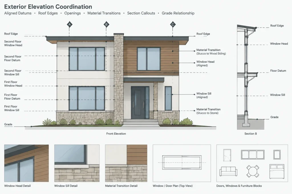
Use elevation dimensions selectively
Vertical dimensions should document controlling relationships, not create an independent chain of values that can conflict with levels and sections. Use the project’s agreed datum and dimensioning method. Confirm whether a dimension refers to finished surfaces, structural geometry, openings, or another defined reference.
Horizontal dimensions are often better located on plans, enlarged elevations, or details, but they may be useful when façade composition or finish modules require direct control. Coordinate any repeated dimensions with their primary source.
Coordinate elevations with the rest of the drawing set
Elevation coordination is an ongoing process rather than a final drafting task. Whenever plans or sections change, review the affected façades. A simple revision to a wall, window, roof edge, or grade condition may alter several elevations and associated details.
Use this review sequence:
- Compare building corners and wall offsets with every relevant floor plan.
- Check opening positions and tags against plans and schedules.
- Compare floor, roof, parapet, and canopy heights with sections.
- Verify roof slopes and drainage-related forms against the roof plan.
- Review material boundaries against finish information and details.
- Confirm exterior stairs, guards, and railings in plan, section, and elevation.
- Check visible equipment and penetrations with consultant information.
- Verify that callouts point to current details and sheet locations.
Do not assume that an external reference guarantees coordination. References can display current geometry, but sheet-specific linework, tags, masking, and annotations may still become outdated.
Final CAD quality-control checklist
Before issuing or plotting the sheet, inspect both the model-space geometry and the paper-space presentation:
- The façade corresponds to the correct viewing direction.
- Building extents, openings, roof forms, and grade are coordinated.
- Projection lines and temporary drafting objects do not plot.
- Duplicate lines and overlapping blocks have been removed.
- Hatches remain inside their intended boundaries.
- Lineweights make foreground, background, and surface information legible.
- Material tags and notes use consistent terminology.
- Levels and dimensions reference the correct project datums.
- Detail and section references are complete and current.
- Text, symbols, and patterns are readable at the sheet’s plotted scale.
A successful exterior elevation is more than a traced façade. It is a coordinated architectural view that explains vertical design intent while remaining connected to the plans, sections, schedules, and details. By projecting from controlled geometry, building the drawing in logical stages, and reviewing it at plot scale, CAD users can create elevations that are both efficient to revise and clear to read.