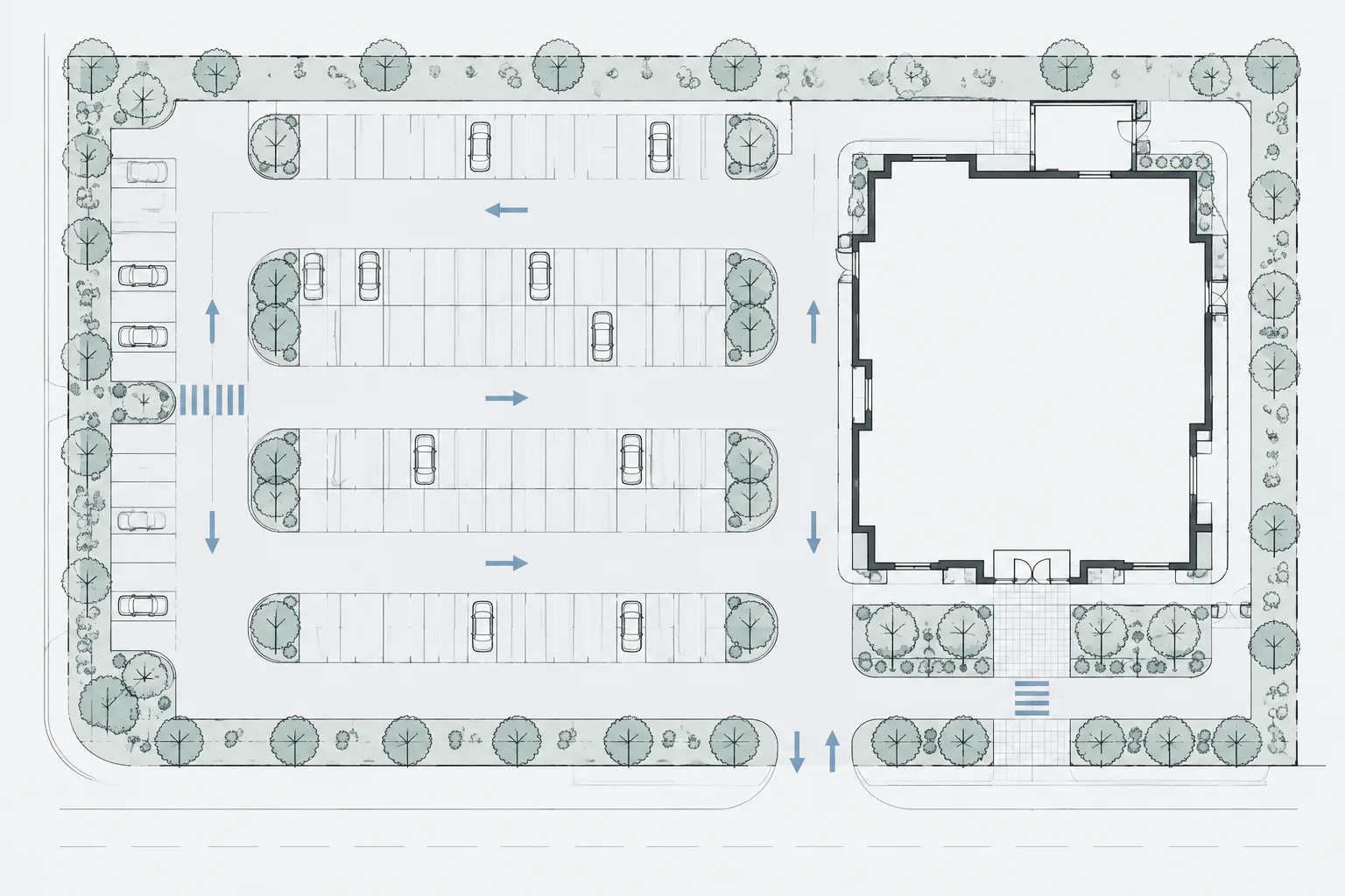
Drafting a parking plan requires more than placing repeated vehicle-space geometry. The CAD file must connect site constraints, vehicle circulation, pedestrian access, service operations, landscape elements, and clear annotation in a coordinated drawing.
The workflow below focuses on how to organize, test, and review a parking layout in architectural CAD. It does not replace project-specific criteria, consultant coordination, accessibility review, or approval by the authorities responsible for the site.
A parking plan is more than a repeated row of vehicle blocks. It must respond to property boundaries, buildings, entrances, circulation, pedestrian movement, grading, landscape areas, utilities, and applicable regulations. A clean parking layout in architectural CAD makes these relationships visible while remaining easy to revise as the site design develops.
This guide explains a practical drafting and coordination workflow without prescribing universal parking dimensions. Stall sizes, aisle widths, accessible parking requirements, fire access criteria, setbacks, and landscape provisions vary by jurisdiction and project. Confirm those requirements with the current project criteria before treating a conceptual layout as a compliant design.
Begin with a verified site background
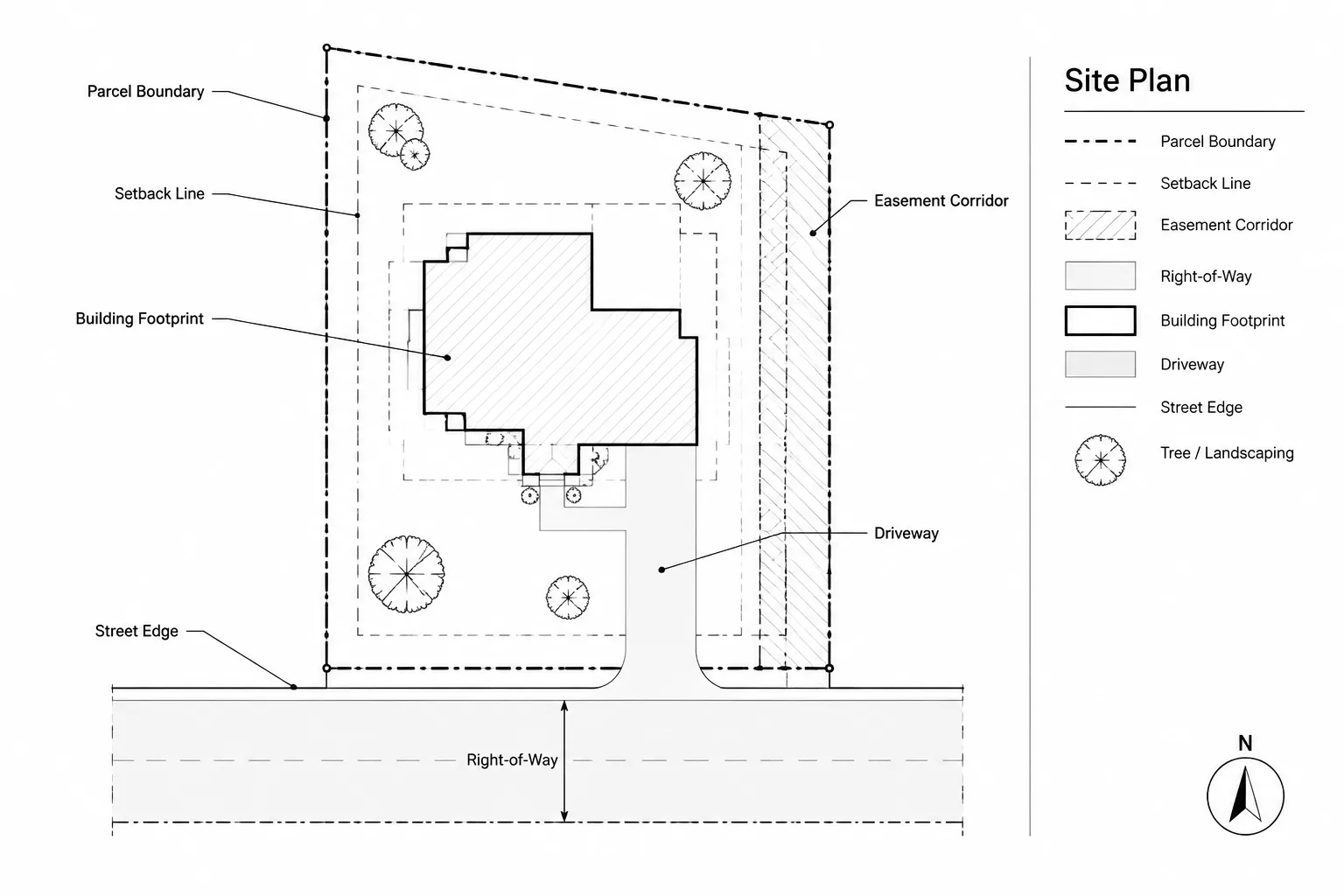
Start from the best available survey or civil base rather than drawing over an image of the property. The background should identify the project limits and the physical constraints that can control the layout.
- Property lines, easements, and rights-of-way
- Existing and proposed buildings
- Curbs, sidewalks, roads, and driveway connections
- Topographic information and significant grade changes
- Drainage structures, utilities, and utility restrictions
- Protected landscape or environmental areas
- Existing features that will remain or be removed
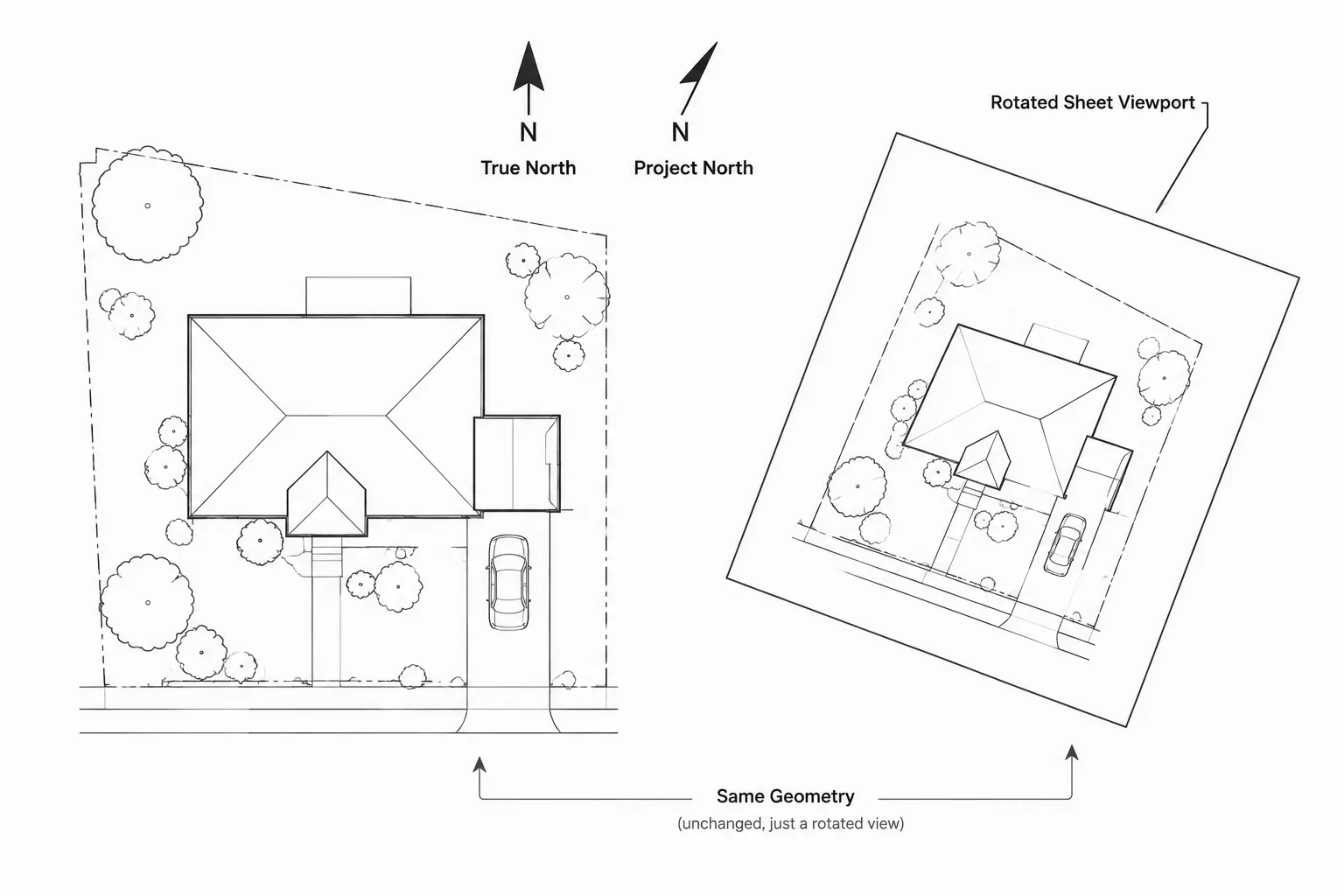
Before drafting, verify the drawing units, coordinate system, orientation, and reference scale. If the survey is attached as an external reference, keep it at its original coordinates whenever the project workflow permits. Moving or rotating a survey casually can create coordination problems when civil, landscape, and architectural files are exchanged.
Separate design geometry from reference information
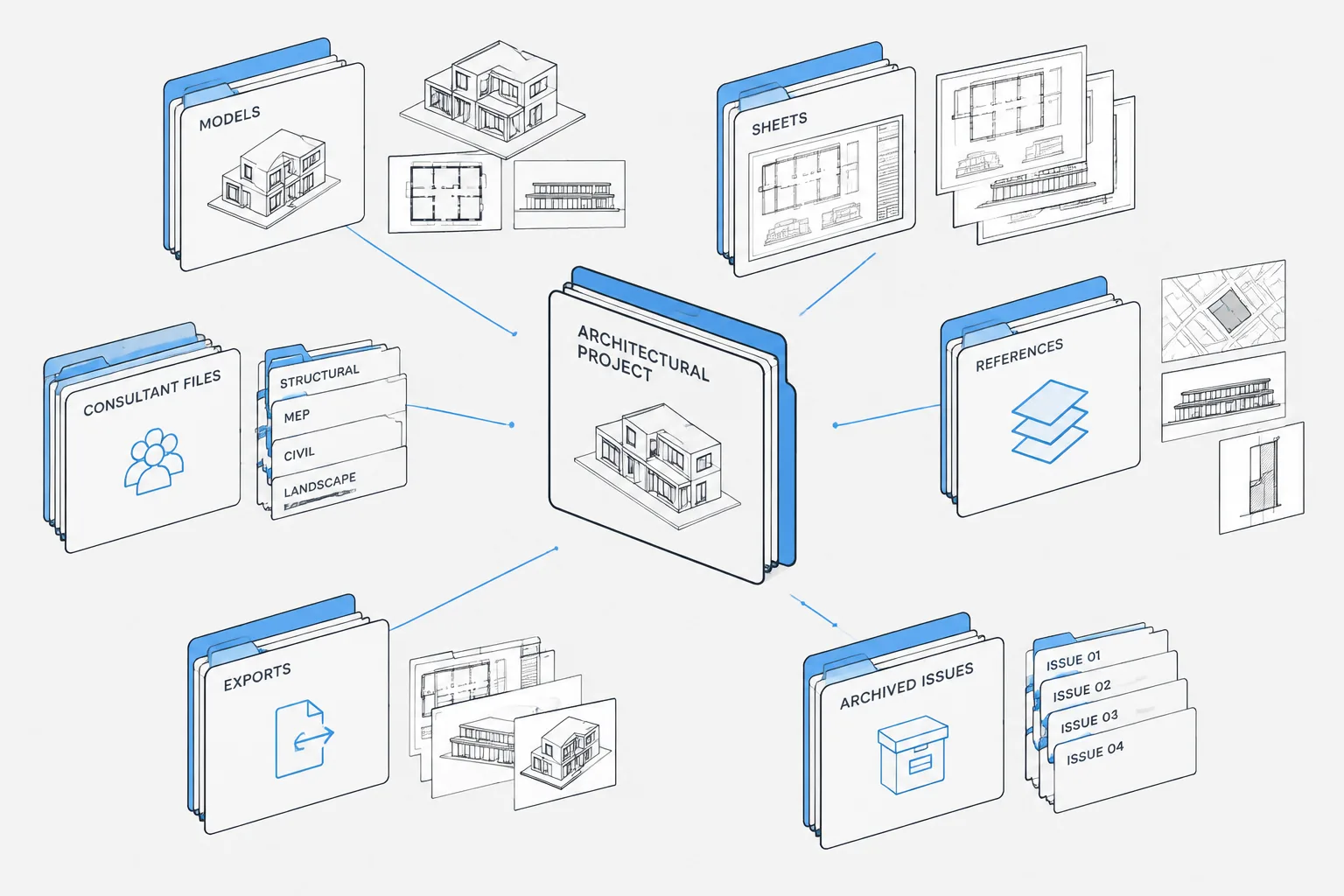
Use a clear layer structure so that parking geometry can be reviewed independently from the survey background. The exact layer names should follow the office CAD standard, but the information should remain logically separated.
| Information group | Typical contents | Drafting purpose |
|---|---|---|
| Reference base | Survey, civil background, property limits, utilities | Provides verified site context |
| Parking geometry | Stall lines, end lines, accessible space markings | Defines the parking arrangement |
| Circulation | Drive aisles, arrows, entrances, turning paths | Explains vehicle movement |
| Pedestrian routes | Walkways, crossings, curb connections | Shows movement between parking and destinations |
| Site elements | Curbs, islands, wheel stops, barriers, signs | Coordinates physical site components |
| Annotation | Dimensions, notes, counts, and labels | Communicates design intent |
Avoid placing all site work on one layer. Separate layers allow designers to test options, isolate conflicts, control plotting, and issue a readable plan without altering the reference file.
Establish the circulation framework first
Parking rows should follow a clear circulation concept. Before arraying stalls, sketch the primary route from the site entrance to the parking areas, building drop-off points, loading zones, and exits. Identify whether each drive aisle is intended for one-way or two-way movement, then coordinate the parking angle and directional arrows with that decision.
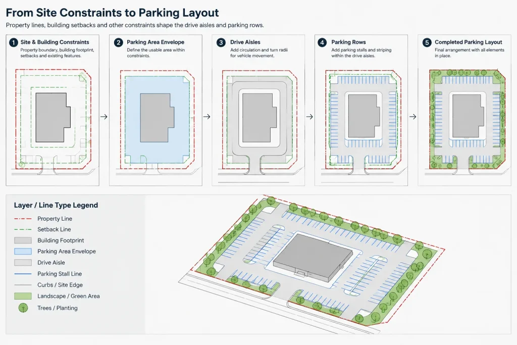
Trace curb returns, medians, islands, and building-side drives as continuous geometry where practical. Closed polylines are useful for paved areas and islands because they support area checks, hatching, and later revisions. Keep centerlines or construction lines on nonplotting layers if they are needed to maintain alignment.
Check connections rather than isolated rows
A parking row may appear efficient by itself but fail where it meets an entrance, cross aisle, building corner, or dead end. Review the complete movement path. Look for abrupt offsets, unclear priority, narrow pinch points, and areas where reversing vehicles may conflict with pedestrians or queued vehicles.
Build parking stalls from controlled geometry
Draft a typical stall module using dimensions verified for the project. A module may be a block, a grouped set of lines, or controlled source geometry that can be copied and arrayed. Whichever method is used, preserve an understandable insertion point and orientation.
Use arrays or evenly spaced copies to establish preliminary rows, but do not leave the result as an unexamined pattern. Break or edit the repeated geometry where rows meet islands, columns, walls, ramps, landscape zones, or other restrictions. Remove partial stalls that could be mistaken for usable spaces.
For angled parking, establish the curb or row baseline first. Construct the stall lines at the intended angle, verify the resulting clear geometry, and then repeat the module. Do not assume that a downloaded parking block has the correct dimensions, angle, units, or linework for the project.
Count actual spaces, not line intervals
Parking counts should be based on complete, usable spaces. If blocks represent stalls, attributes or data extraction may help with counting, but the result still needs visual review. If stalls are drafted as lines, use a consistent counting method and record the count in a schedule or plan note that can be checked against the drawing.
Separate categories when the project requires them, such as standard spaces, accessible spaces, compact spaces, electric-vehicle spaces, loading spaces, or spaces assigned to a particular use. Do not infer category requirements from a generic CAD template.
Coordinate accessible parking with the full route
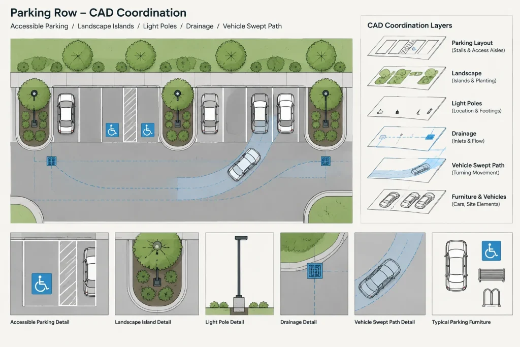
Accessible parking cannot be coordinated only as a special stall symbol. Review the parking space, access aisle, curb transition, pedestrian route, entrance location, surface conditions, signs, and potential vehicle overhangs as one connected arrangement.
Use dimensions and notes confirmed for the governing jurisdiction and project type. Requirements may depend on the parking count, facility use, vehicle type, route configuration, and local adoption. Keep access aisles and pedestrian paths graphically distinct from ordinary striping so they remain legible in both model space and plotted sheets.
Test vehicle movement with appropriate templates
Turning paths are valuable coordination tools, but they are not decorative symbols. Use a vehicle template that represents the design vehicle established by the project team. A passenger car, delivery vehicle, refuse vehicle, emergency vehicle, and moving truck can produce very different path requirements.
Place turning-path geometry on a dedicated review layer. Check entrances, tight corners, parking row ends, loading areas, drop-off loops, gates, ramps, and dead-end turnarounds. Consider both the vehicle body and its swept path rather than tracing only the wheel path.
Vehicle simulation results depend on assumptions about speed, steering, driver behavior, and vehicle geometry. Treat them as coordination evidence to be reviewed by the responsible design discipline, not as automatic approval.
Add pedestrian, landscape, and service relationships
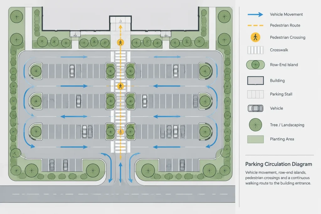
A strong parking plan shows how people move after leaving a vehicle. Draw walkways and crossings early enough to influence the parking arrangement. Direct routes to primary entrances are generally easier to understand than paths that weave behind parked vehicles, but every project must respond to its own site constraints.
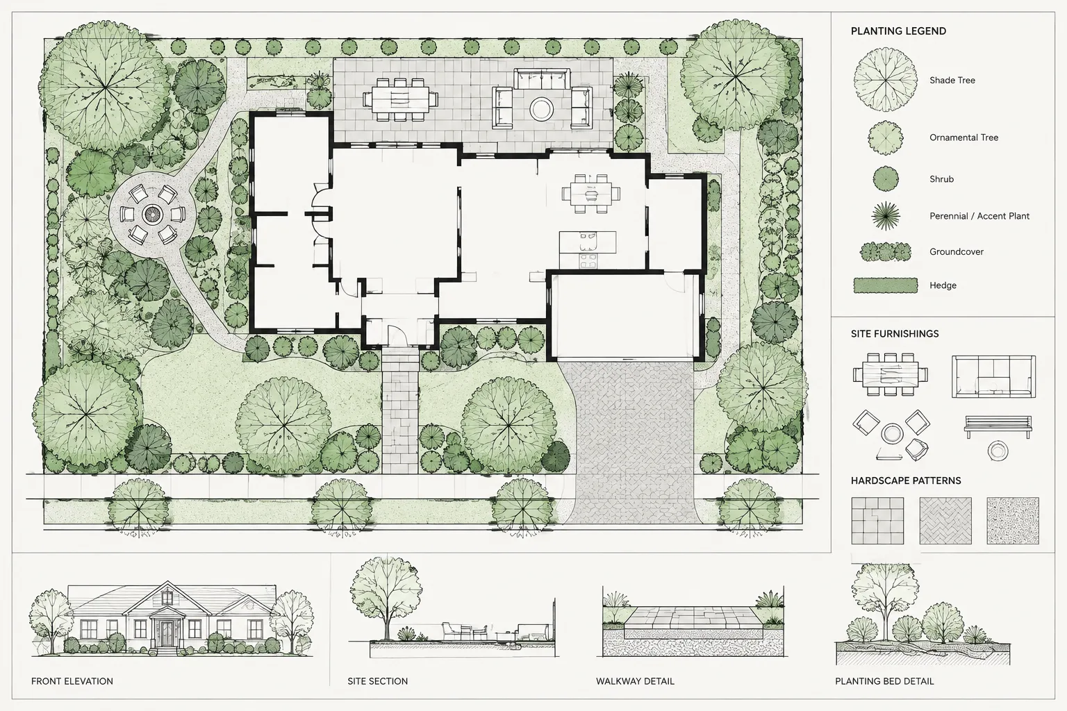
Coordinate islands and landscape areas with stall ends, sightlines, lighting, drainage, snow-management needs where relevant, and vehicle overhang. Confirm that trees, poles, signs, hydrants, utility cabinets, and similar elements do not occupy required movement or visibility zones.
Loading, refuse collection, delivery, and service access also need deliberate geometry. Show the operational area needed for the selected service approach, and prevent routine service movements from blocking primary pedestrian routes or trapping parked vehicles.
Dimension for verification, not decoration
Dimensions should help reviewers confirm the design. Prioritize dimensions that establish the controlling geometry, including overall parking bays, typical stalls, drive aisles, offsets from buildings, island locations, and critical site connections. Avoid dimensioning every repeated line when a typical dimension and a clear layout communicate the same intent.
Keep dimensions associative when the office workflow supports it, and place them on dedicated annotation layers. After significant revisions, inspect dimension origins rather than assuming all strings updated correctly. Notes should identify unusual conditions, but they should not substitute for visible geometry.
Run a parking-plan quality-control review
Before sharing or plotting the drawing, perform a focused review:
- Confirm that the latest survey and architectural backgrounds are referenced.
- Check property constraints, easements, and required setbacks against verified criteria.
- Verify parking modules, angles, and categories using current project information.
- Review entrances, drive aisles, row ends, and dead ends for understandable circulation.
- Check designated vehicle turning paths with the correct project vehicle assumptions.
- Trace pedestrian routes continuously from parking areas to building entrances.
- Coordinate accessible spaces, access aisles, curb transitions, routes, and signs.
- Review conflicts with columns, curbs, landscape elements, utilities, lighting, and drainage.
- Recount spaces after every layout revision.
- Plot at the intended sheet scale and confirm that striping, symbols, arrows, and notes remain readable.
Keep conceptual and verified information distinct
Early parking studies often use provisional modules to compare layout options. Label those studies appropriately and avoid presenting conceptual geometry as a verified construction plan. Once project criteria are confirmed, update the source modules, recount the spaces, and repeat the circulation and coordination checks.
A reliable parking layout in architectural CAD is built through controlled geometry and multidisciplinary review. By establishing circulation first, using verified modules, coordinating pedestrian and service needs, and maintaining clear layers and annotations, the drawing becomes more than a pattern of stalls: it becomes a useful site-planning and decision-making tool.
Use the parking plan as a coordination record
A well-managed parking drawing should make design decisions traceable. Reviewers need to distinguish referenced conditions from proposed geometry, identify which vehicle and stall assumptions were used, and understand whether the plan is conceptual or based on verified project criteria.
When the layout changes, review the effects beyond the edited row. A shifted curb or island may affect circulation, pedestrian routes, drainage coordination, landscape space, lighting locations, service access, and the parking count. Treat each revision as a site-wide coordination change rather than an isolated drafting correction.
Prepare a clear consultant handoff
- Keep referenced backgrounds separate from editable parking geometry.
- Identify the source and status of the project criteria used for the layout.
- Remove abandoned options or place them on clearly controlled nonplotting layers.
- Confirm that blocks, linework, labels, and schedules communicate the same parking categories.
- Flag unresolved turning, grading, utility, accessibility, or landscape questions for the responsible discipline.
- Issue a plotted review sheet with the CAD file so recipients can compare the intended graphic result.
This approach helps prevent a visually complete drawing from being mistaken for a fully coordinated design. Final suitability depends on verified site information, current project requirements, and review by the appropriate professionals.
Parking Layout CAD Frequently Asked Questions
Should parking stalls be drawn as blocks or individual lines?
Either method can work. Blocks support consistent insertion, category identification, and counting, while controlled linework can be convenient where row geometry changes frequently. The important points are verified source geometry, clear orientation, consistent layers, and a counting method that can be checked visually.
Why should circulation be drafted before parking rows?
Circulation establishes how vehicles enter, move through, and leave the site. Starting with repeated stalls can produce efficient-looking rows that create conflicts at entrances, intersections, dead ends, loading areas, or building approaches.
Can a downloaded parking CAD block be used without modification?
It should be checked before use. Confirm its units, scale, insertion point, orientation, layer assignments, linework, and relationship to the verified project criteria. A generic block is drafting geometry, not evidence of compliance.
How should parking counts be maintained during revisions?
Use complete spaces as the basis of the count and separate any required categories. Automated extraction can assist when consistent attributed blocks are used, but the reported result should still be compared with the visible plan after each layout change.
What should be included in a parking-plan coordination review?
Review the current backgrounds, property constraints, circulation, turning assumptions, pedestrian routes, accessible parking arrangement, service access, site elements, annotations, category counts, and plotted readability. Unresolved issues should be identified rather than hidden by finished-looking graphics.
Does a turning-path diagram prove that a layout is acceptable?
No. Its usefulness depends on the selected design vehicle and the assumptions used to generate the path. It is a coordination tool that must be interpreted and reviewed by the responsible project disciplines.