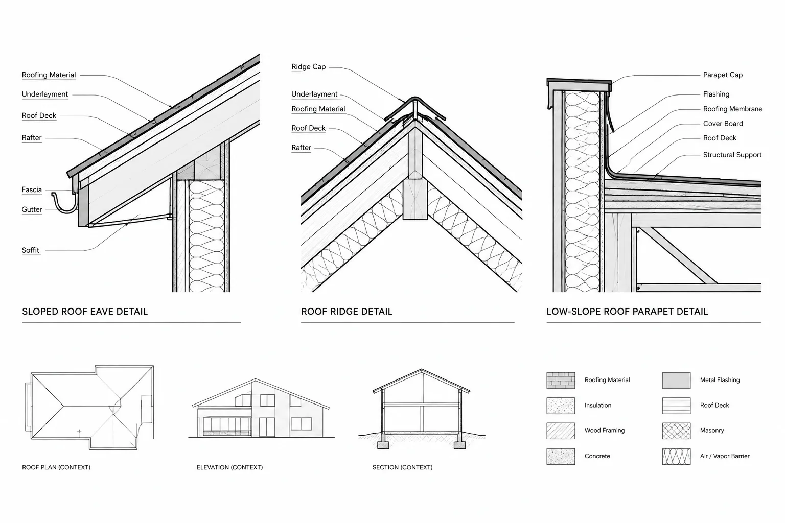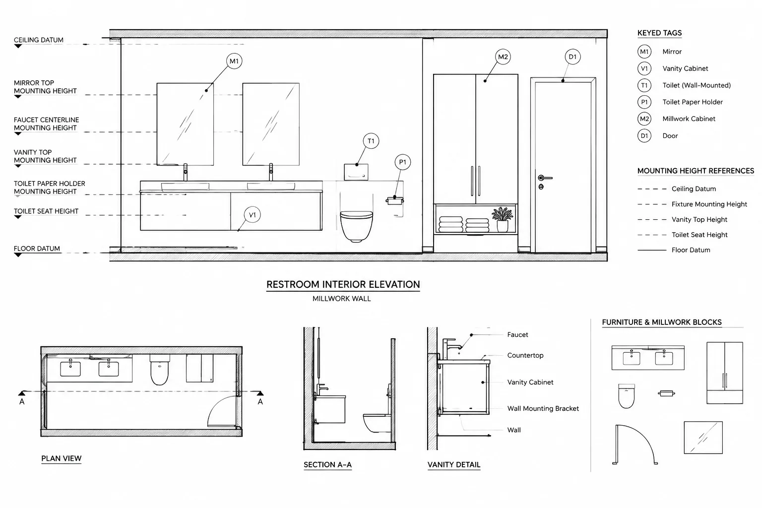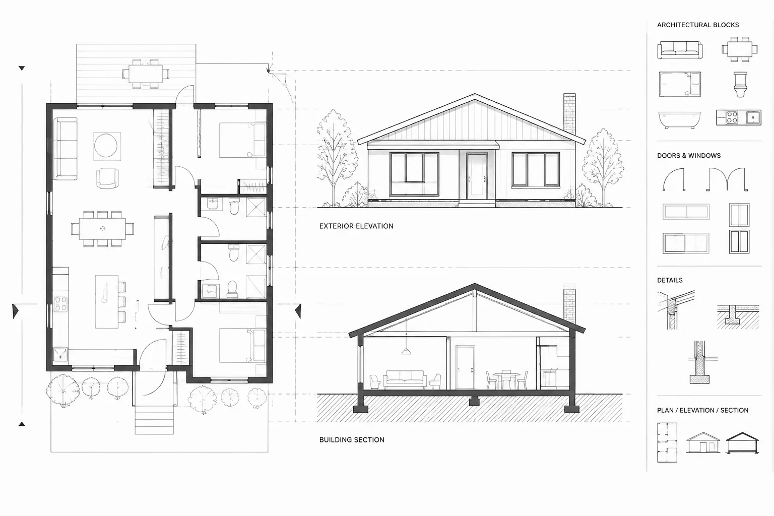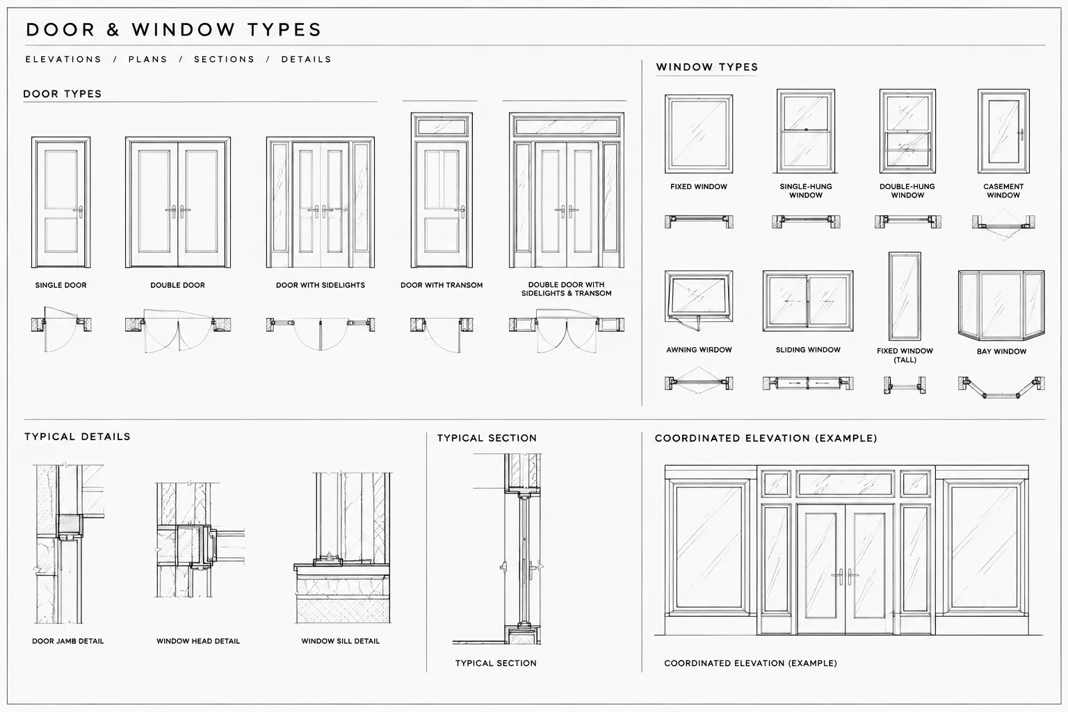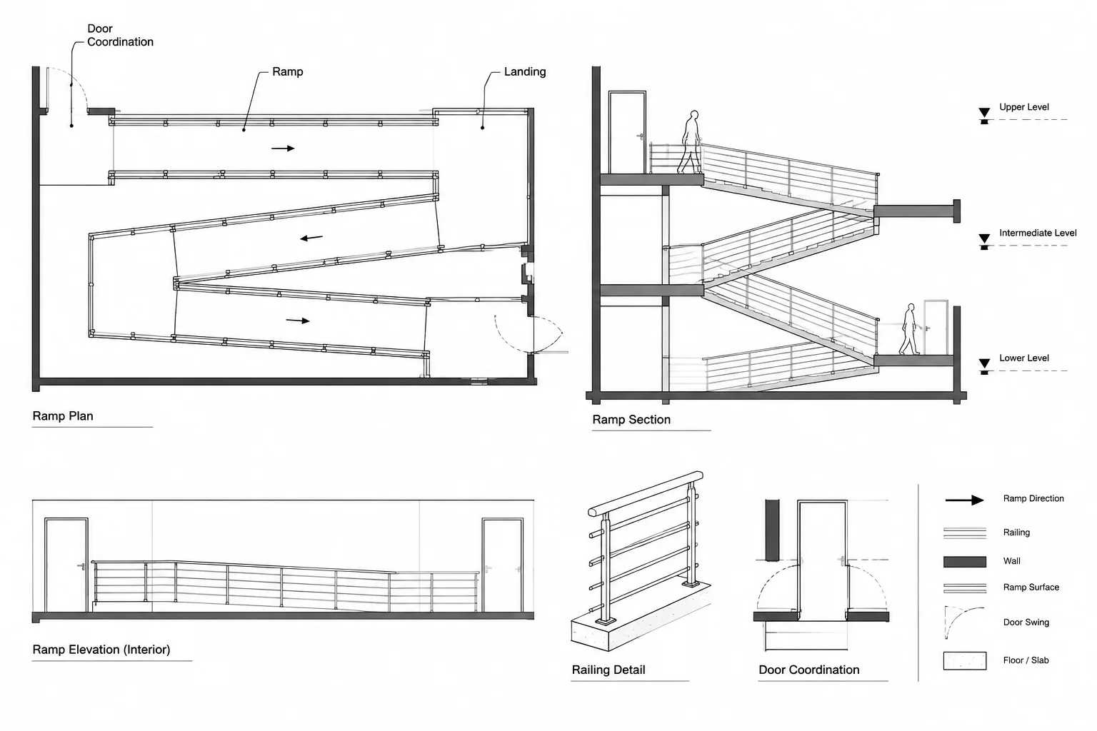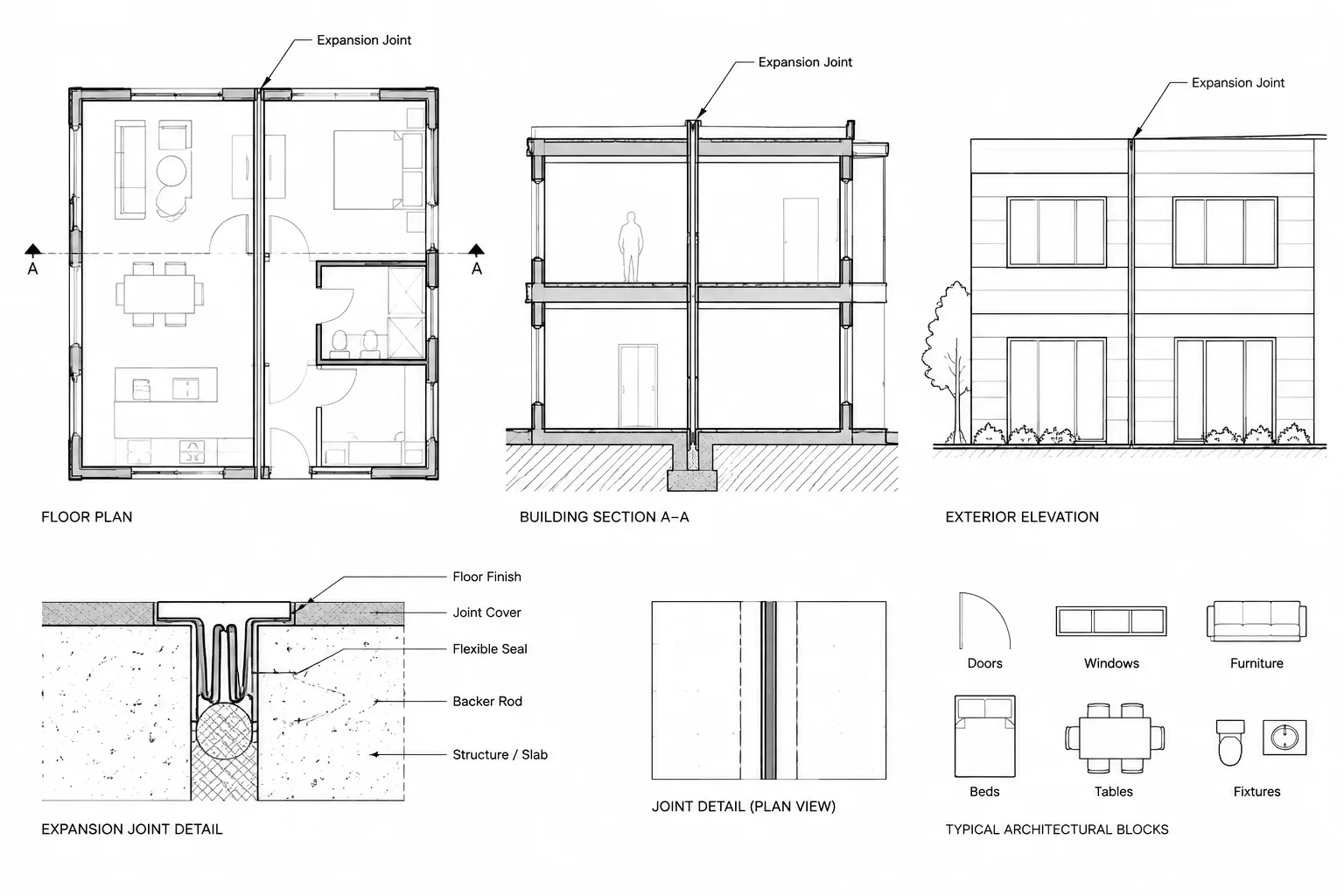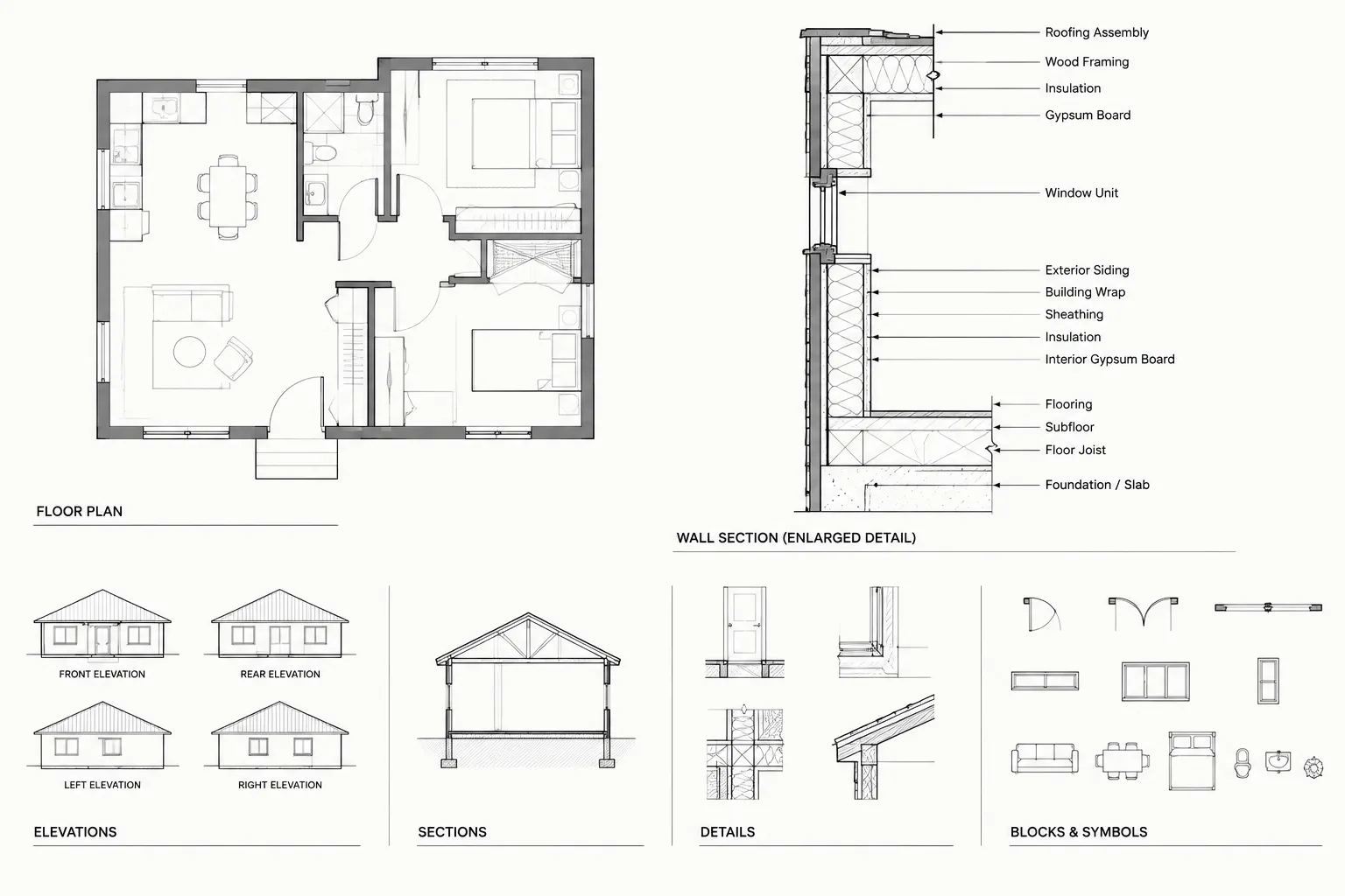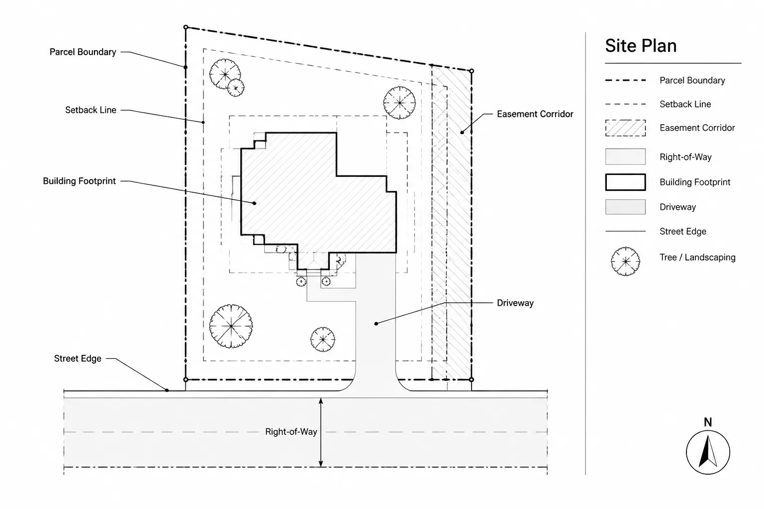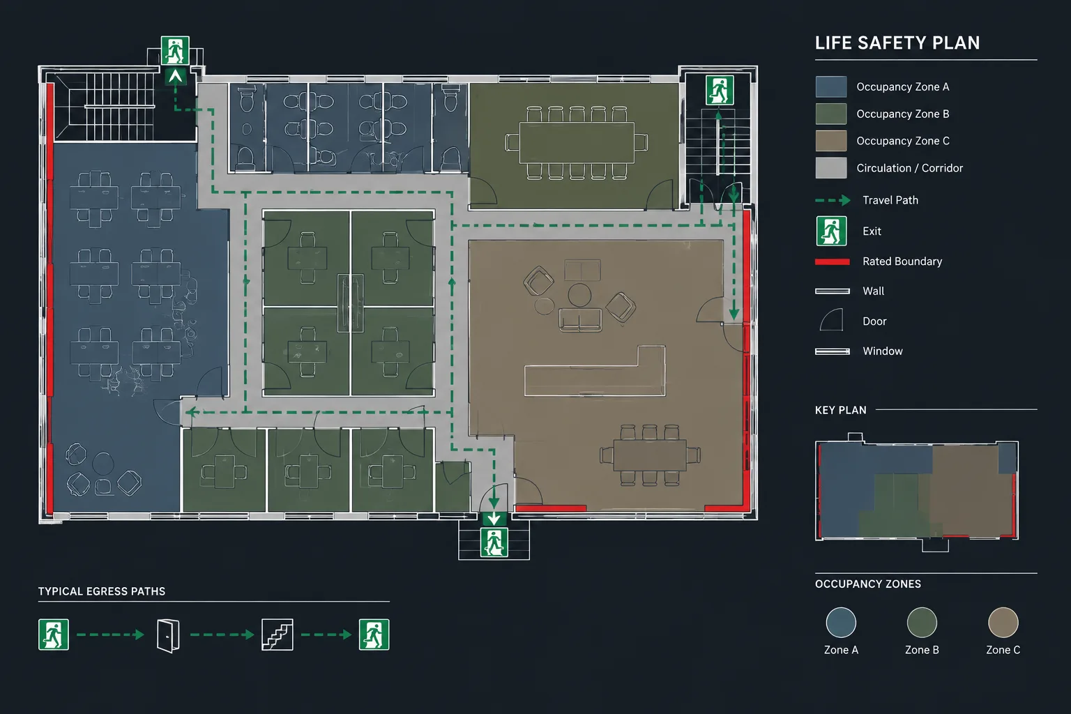
A well-organized life safety plan in CAD connects architectural geometry with reviewed code-analysis information. The drafter’s role is to present that information clearly, maintain its relationship to the current design, and make changes easy to identify during coordination.
This guide explains a practical drawing workflow for backgrounds, layers, travel paths, occupancy areas, rated construction, legends, and quality control. It focuses on drafting and coordination rather than establishing project compliance, which remains the responsibility of the qualified professionals reviewing the applicable requirements.
A life safety plan translates code analysis and project decisions into a coordinated architectural drawing. It may communicate occupancy information, exit access, exits, travel paths, rated separations, door conditions, occupant loads, and other items requested by the permitting authority or project team.
Although it is often built from the architectural floor plan, a life safety plan is not simply another background with colored arrows added. Its information must agree with the current design, the applicable code analysis, door data, wall types, and supporting consultant drawings. The drafting process should make that information legible without implying that an unverified CAD symbol or downloaded block establishes compliance.
Define the drawing’s purpose before drafting
Life safety drawing requirements vary by jurisdiction, building type, project scope, and submission stage. Before creating layers or symbols, determine what the plan is expected to communicate. A permitting diagram may differ from an internal egress study or a construction-document sheet.
Confirm the governing criteria with the responsible architect or code professional. The CAD drafter should receive documented direction rather than infer requirements from a previous project. At minimum, clarify which plan levels are included, which code analysis is current, what classifications and calculations must appear, and whether supporting diagrams or schedules are required.
Create a short content checklist for the project. Depending on the approved drawing scope, it may include:
- Occupancy or use classifications and boundaries
- Room or area occupant-load information
- Exit-access paths and travel-distance measurements
- Required exits and discharge routes
- Rated walls, barriers, partitions, floors, or horizontal assemblies
- Protected openings and relevant door information
- Areas of refuge, accessible means of egress, or similar project-specific provisions
- Fire and smoke protection features identified by the code analysis
- Legends, calculation tables, and general notes
This list is not a substitute for a project-specific code review. It is a framework for organizing information after the required content has been identified.
Start from a controlled architectural background
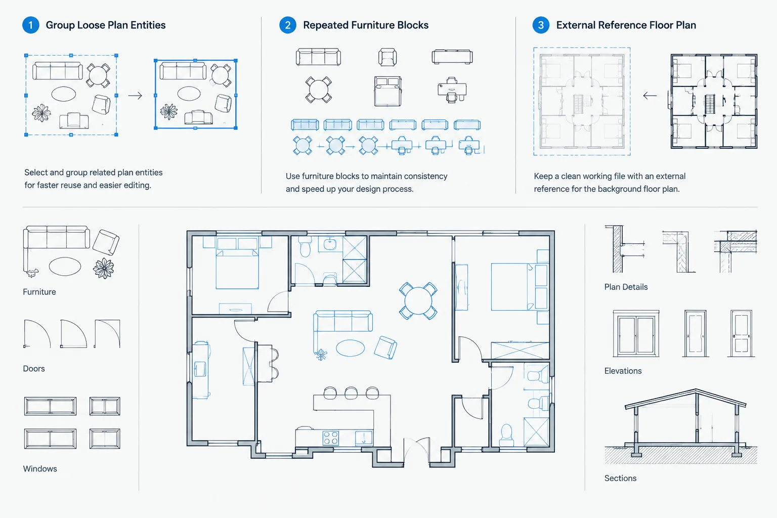
Use the current architectural plan as an external reference whenever the project workflow permits. A referenced background reduces duplicate geometry and helps expose design changes. Avoid copying walls, doors, and rooms into an independent life safety file unless the file structure requires it, because copied plans can become outdated without an obvious warning.
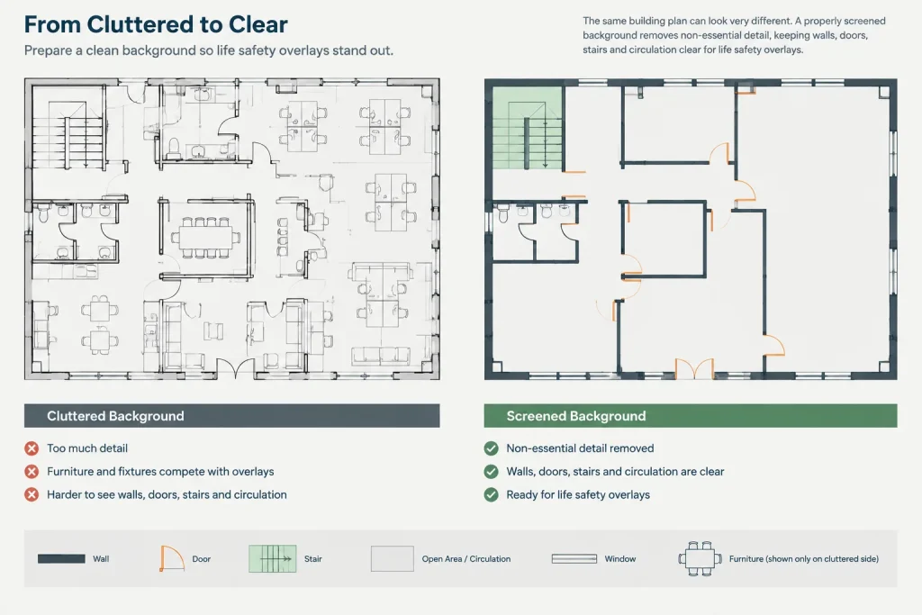
Display only the background information needed to understand the analysis. Furniture, finish patterns, minor casework, and dense dimensions can obscure travel paths and rated boundaries. Keep essential walls, openings, stairs, room identifiers, and circulation geometry visible. Apply a restrained graphic treatment to the background so that life safety information remains dominant.
Check the base plan before analysis graphics
- Verify that the correct floor and project area are referenced.
- Confirm drawing units and the reference scale.
- Check that doors, stairs, ramps, and exterior discharge points match the latest plans.
- Review room names and boundaries against the current program.
- Look for unresolved design options or hidden layers that could change the analysis.
A travel path drawn accurately over an obsolete plan is still incorrect. Background verification should occur before drafting and again before issue.
Separate analysis graphics from building geometry
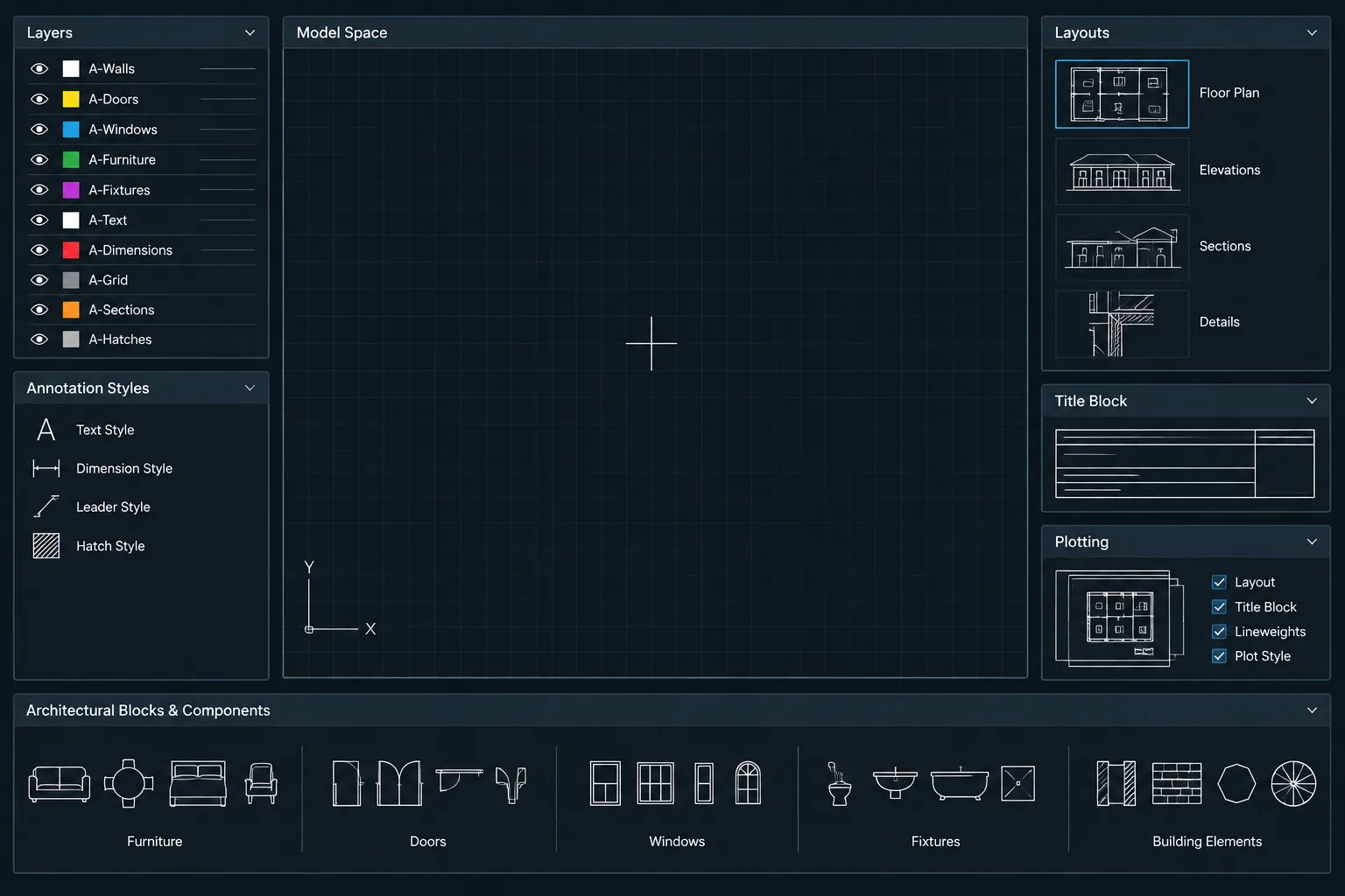
Place life safety information on dedicated, clearly named layers. The exact naming system should follow the office standard, but separate layers are useful for travel paths, rated boundaries, occupancy areas, symbols, text, and calculation graphics. This allows the team to control plotting, isolate information for review, and update one category without disturbing another.
| Information category | Useful CAD treatment | Coordination concern |
|---|---|---|
| Travel paths | Distinct polylines with clear directional graphics | Must follow the analyzed route rather than cutting through obstacles |
| Occupancy areas | Closed boundaries, light hatches, or keyed fills | Boundaries must agree with the calculation method |
| Rated construction | Consistent linework or coded graphic overlays | Must match wall types, details, and door information |
| Exit and protection symbols | Controlled blocks with readable labels | Symbols should represent verified project conditions |
| Calculations and notes | Tables or aligned text fields | Values need a traceable source and review process |
Do not encode critical meaning through color alone. Drawings may be printed in grayscale, viewed on different displays, or reproduced at reduced size. Combine color with line type, lineweight, hatch, text, or symbols so that the plan remains understandable in its intended output format.
Draft travel paths as measurable geometry
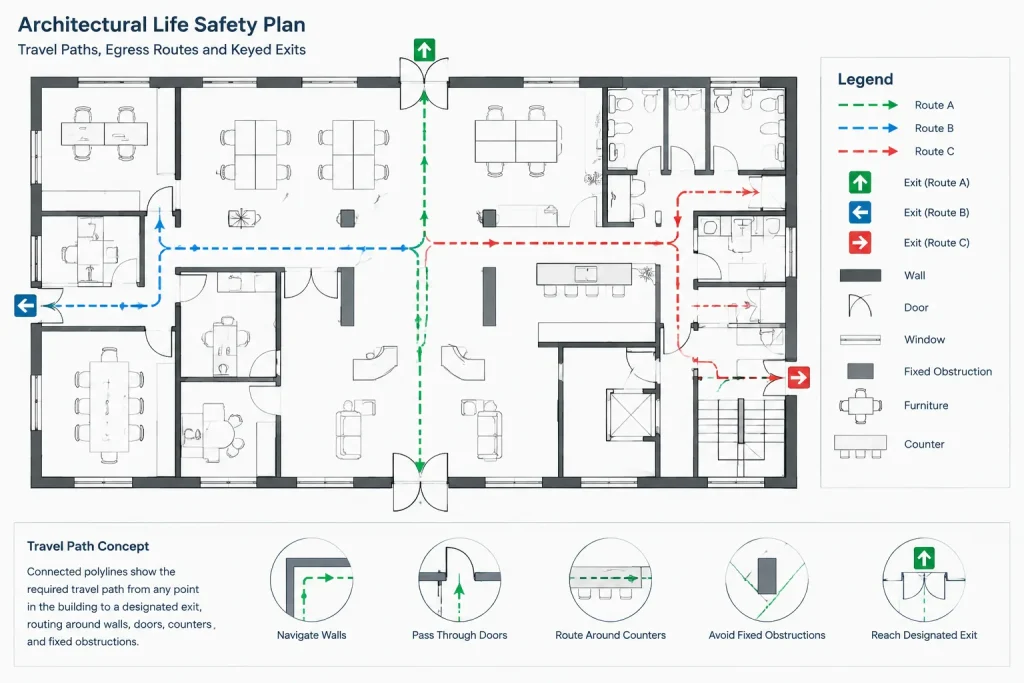
Use connected polylines or another consistently measurable method for travel routes. Place vertices where the path changes direction and route the line through the actual circulation path shown by the plan. Do not draw a direct diagonal through walls, fixed equipment, counters, or other obstructions simply because it produces a shorter distance.
Travel-distance rules and measurement conventions depend on the applicable requirements and project conditions. The responsible professional should establish where measurement begins, where it ends, and how the route passes through rooms, doors, stairs, and exterior areas. CAD provides the geometric length; it does not determine whether the measurement method is correct.
Keep route labels associated with their paths. If several paths overlap, adjust the graphic organization without changing the analyzed route. Separate studies by area or use keyed identifiers when the full plan becomes difficult to read.
Coordinate occupancy areas and calculations
Occupancy calculations should be based on reviewed area boundaries and documented factors supplied by the code analysis. Create closed polylines for measured areas where appropriate, and check them for gaps, overlaps, duplicated segments, and unintended islands.
Distinguish between different area concepts used by the project. Room area, department area, code-analysis area, lease area, and gross building area may not share the same boundaries. A CAD field or automated area label can help maintain consistency, but automation does not validate the selected boundary or classification.
Use a calculation table that connects each result to a recognizable plan area. A practical table may identify an area key, use or classification, measured area, approved factor, calculated result, and any rounding method directed by the responsible professional. Do not reuse factors or assumptions from another project without verification.
Show rated construction without concealing the plan
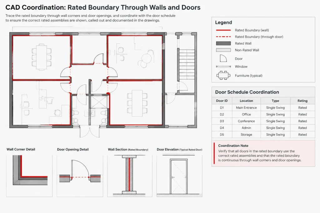
Rated assemblies often require coordination across plans, wall types, door schedules, sections, and details. On the life safety plan, use a consistent overlay or symbol system that makes each reviewed condition easy to trace. Avoid placing a heavy line directly over wall geometry if it hides intersections, openings, or changes in wall type.
Check each rated boundary as a continuous path. Follow it through corners, shafts, doors, curtain wall interfaces, floor edges, and transitions between construction types. A visually continuous CAD line can still conceal an unresolved physical junction, so flag ambiguous locations for design review rather than drafting around them.
Door labels associated with protected openings should coordinate with the door schedule and hardware information. The life safety plan should not become an independent source of conflicting door data.
Build a project-specific legend
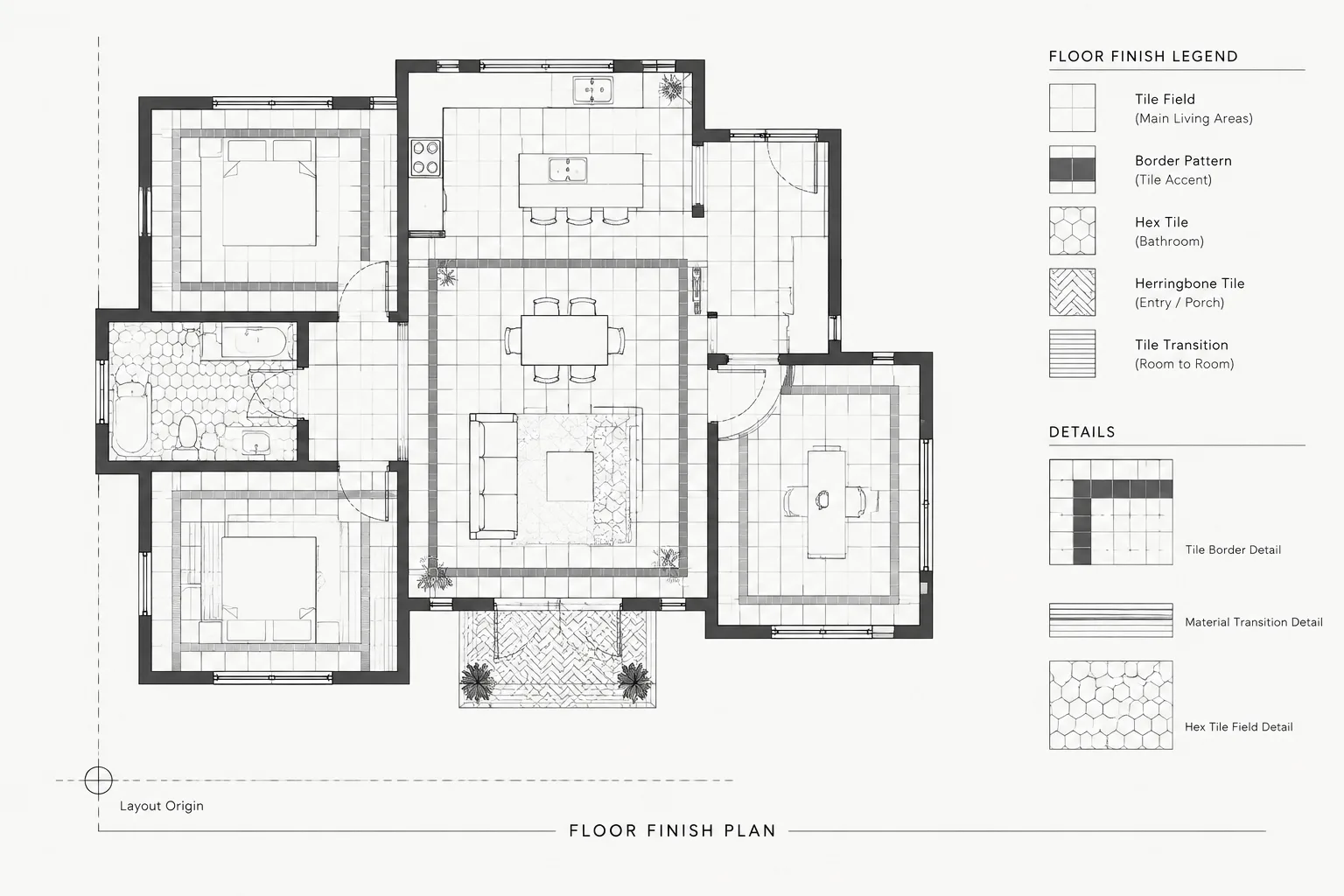
A legend should explain the symbols and graphic conventions actually used on the sheet. Remove inherited symbols that do not occur in the project. Unused entries create uncertainty and can suggest that features exist when they do not.
Keep blocks simple and readable at the plotted scale. Use attributes only when they improve coordination, such as carrying an identifier that can be checked against a schedule. Avoid embedding unverified technical statements inside reusable blocks. A generic symbol can be reused; its project-specific classification, rating, or status must be confirmed each time.
Run coordinated quality-control checks
Review the plan both as CAD geometry and as a construction-document graphic. Isolation tools can help check individual layers, while a plotted PDF review reveals lineweight, masking, color, and legibility problems.
Geometry and data checks
- Confirm that area boundaries are closed and do not overlap unintentionally.
- Recalculate path lengths after plan changes.
- Check that routes pass through current door locations.
- Compare occupancy-area keys with the calculation table.
- Verify that every symbol is defined in the legend.
Cross-drawing checks
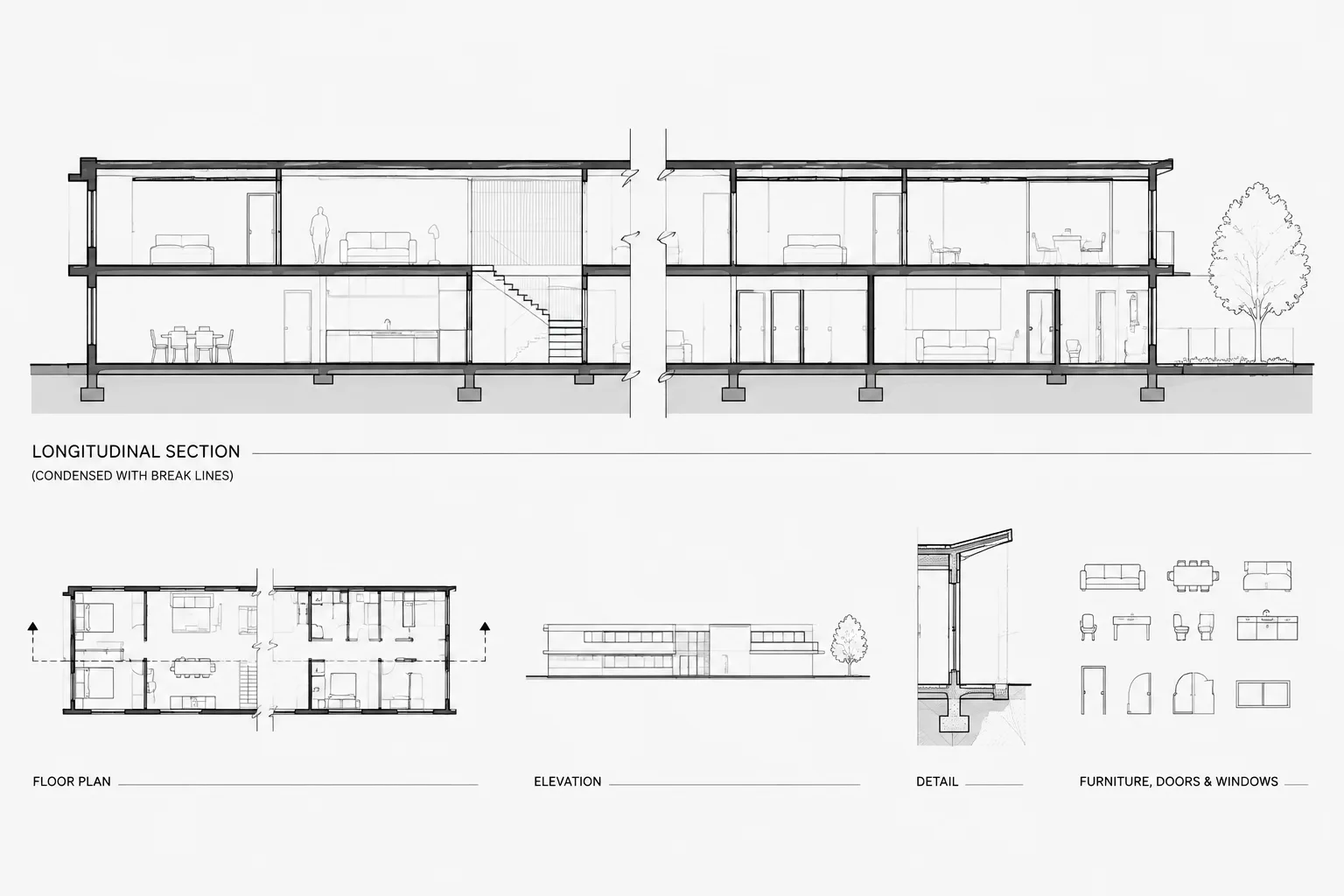
- Compare rated boundaries with wall types and assembly details.
- Compare protected openings with the door schedule.
- Coordinate stairs, ramps, and discharge routes with plans and site information.
- Check room names and uses against the latest architectural plans.
- Confirm that relevant consultant information is current and correctly referenced.
Sheet and plotting checks
- Test readability at the intended sheet size and scale.
- Confirm that grayscale output preserves essential distinctions.
- Look for clipped notes, broken hatches, masked symbols, and hidden paths.
- Ensure that the title, level, plan orientation, and revision status are correct.
Treat the plan as a maintained analysis drawing
Life safety information can change when rooms are reclassified, partitions move, doors are relocated, stairs are revised, or construction types change. Include the life safety plan in the normal revision workflow rather than updating it only before a submission deadline.
When a design change affects circulation or separation, identify the related analysis items that require review. A moved door may alter a travel path, a revised room boundary may change an area calculation, and a wall-type change may affect rated continuity. Recording these relationships in the project checklist helps prevent isolated CAD edits.
The strongest life safety plan is not the one with the most colors or symbols. It is the one that clearly presents reviewed information, remains coordinated with the architectural documents, and makes assumptions easy to identify and verify.
Make every graphic traceable to a reviewed source
A useful coordination principle is to identify who owns each category of information before it appears on the drawing. Architectural geometry may come from the current floor plan, door conditions from the door schedule, rated assemblies from reviewed wall types, and calculation criteria from the project’s code analysis. The life safety plan should communicate these sources without becoming an uncontrolled replacement for them.
Where the source is unresolved, use the project’s established review notation rather than presenting an assumption as final. This distinction helps reviewers separate drafting errors from open design or code-analysis questions.
Use a change-impact review
Revisions should be evaluated by relationship, not only by location. When a wall, opening, room use, stair, or exterior route changes, review every connected item that may depend on it. That can include path geometry, area boundaries, labels, rated continuity, schedule references, and calculation graphics.
- Geometry changed: Check paths, boundaries, openings, and discharge connections.
- Room use changed: Check classifications, area keys, calculations, and notes.
- Wall type changed: Check rated overlays, junctions, doors, sections, and details.
- Sheet graphics changed: Check legends, linework hierarchy, masking, and plotted readability.
Review the drawing in more than one mode
An on-screen CAD review is useful for inspecting layers, object properties, references, and measurable geometry. A plotted-sheet review tests whether the information remains understandable after lineweights, hatches, masks, and background graphics are combined. Both reviews are necessary because a geometrically correct object can still be visually ambiguous.
Before issue, a reviewer should be able to follow each route, recognize each analyzed area, interpret every symbol, and connect important conditions to their supporting architectural information. If those relationships are difficult to trace, the drawing needs coordination rather than additional decoration.
Life safety plan CAD questions
Should a life safety plan be drawn in a separate CAD file?
That depends on the office and project workflow. A separate file can isolate analysis graphics, but it should use a controlled reference to the current architectural plan whenever practical. If the graphics are kept in the main plan file, dedicated layers and careful display control are still important.
Can a CAD block confirm that a condition is code compliant?
No. A block is only a graphic or data container. Its meaning must be supported by the reviewed project documents and code analysis. Reusable symbols should not carry unverified project-specific classifications, ratings, or approvals.
Why should travel paths use connected CAD geometry?
Connected geometry supports consistent measurement and makes the route easier to inspect after plan revisions. The geometry must still follow the approved measurement method and actual circulation path; CAD length alone does not validate the analysis.
How should overlapping routes be shown?
Use clear identifiers, controlled offsets, selective display, or separate keyed studies while preserving the analyzed geometry. Graphic separation should improve readability without implying a different route.
What should be checked when the architectural plan changes?
Review affected routes, area boundaries, room classifications, openings, rated construction, labels, calculations, schedules, and legend entries. Also confirm that the referenced background is current and that obsolete geometry is not still visible.
Is color enough to distinguish life safety information?
No. Combine color with line type, lineweight, hatch, text, or symbols so the information remains understandable in grayscale and under different viewing conditions.