
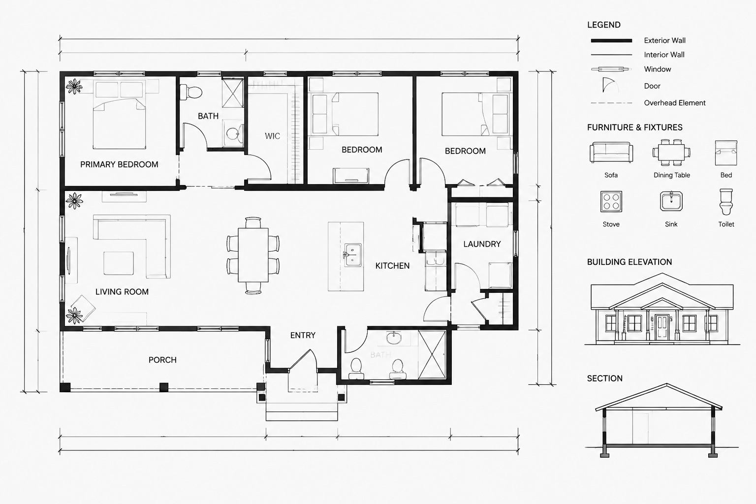
Architectural floor plan dimensioning is not simply the process of adding measurements around a drawing. A useful dimension plan explains where walls, openings, fixtures, and other construction elements belong while remaining readable at the intended sheet scale. It must also stay coordinated when the design changes.
A common drafting mistake is to dimension every visible object. This produces crowded plans, repeated information, and conflicts between dimension strings. A better approach is to identify the geometry that controls construction, organize dimensions by purpose, and apply a consistent hierarchy throughout the drawing set.
Begin with stable plan geometry
Dimensioning should start only after the main plan geometry is reasonably organized. Walls should connect cleanly, openings should be placed intentionally, and grids or reference lines should be coordinated where they are part of the project. Adding dimensions to temporary lines or loosely placed blocks makes later revisions harder to manage.
Before dimensioning, review the plan for:
- Overlapping or duplicate wall lines
- Openings that are not aligned with their host walls
- Blocks inserted at an incorrect scale
- Partitions drawn without a clear locating reference
- Inconsistent wall thicknesses caused by drafting errors
- Fixtures or casework that may still be placeholders
Temporary construction lines can help establish important faces, centerlines, and alignments. Keep these guides on a non-plotting or appropriately managed layer so they do not become accidental drawing content.
Decide what the dimensions are locating
Every dimension should have a clear purpose. It may locate a wall face, a structural grid, the centerline of an opening, the edge of a rough opening, or the face of a fixed component. Mixing these references without a defined convention creates ambiguity.
For example, one opening may be located to its centerline while another is located to its jamb. Both approaches can be useful, but switching between them without explanation makes the plan difficult to interpret. Establish the project convention before placing a large number of dimensions.
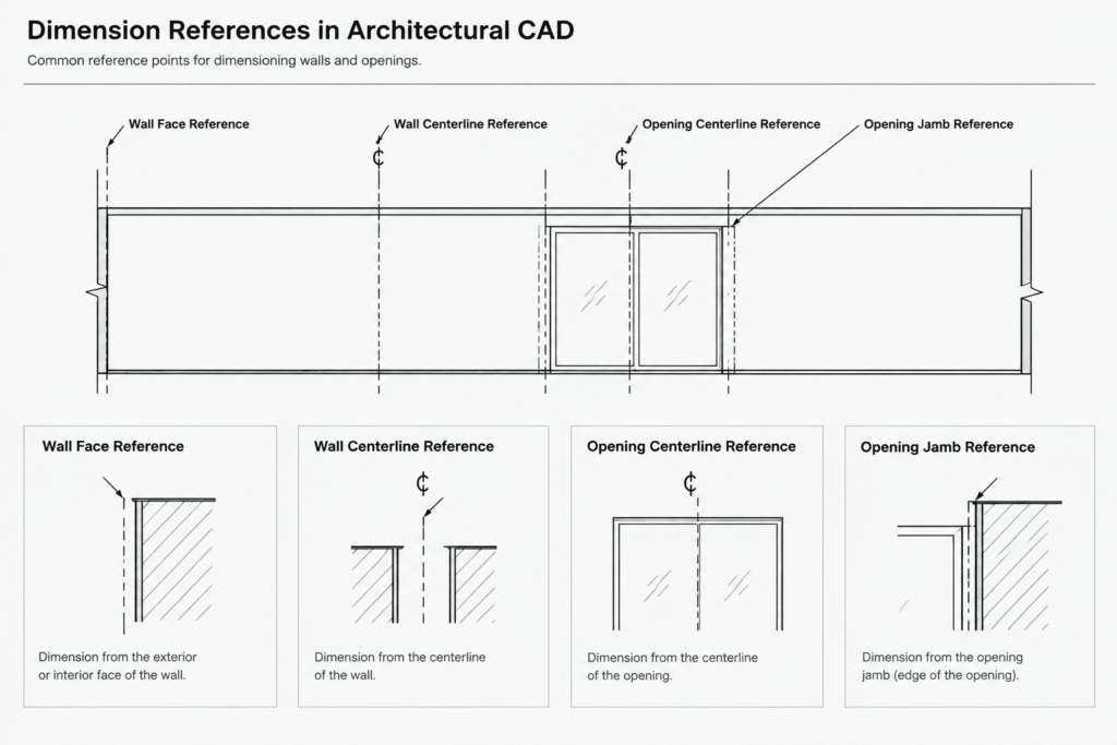
Common dimension references
| Reference | Typical use | Coordination concern |
|---|---|---|
| Wall face | Locating finished spaces, partitions, or clear relationships | Confirm whether the line represents a finish face or another wall component |
| Wall centerline | Symmetrical layouts or selected construction references | Centerlines may not describe the usable room boundary |
| Structural grid | Coordinating major building elements | Architectural dimensions should agree with the current grid layout |
| Opening centerline | Locating regularly arranged doors or windows | The opening width must be documented elsewhere or clearly dimensioned |
| Jamb or opening edge | Controlling the relationship between an opening and an adjacent wall | Avoid adding a second dimension that locates the same edge differently |
| Fixture or casework face | Locating fixed interior components | Verify that the item is fixed work rather than movable furniture |
Build an exterior dimension hierarchy
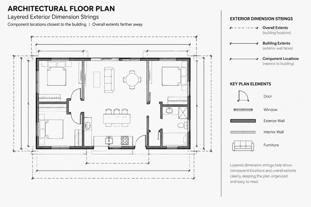
Exterior dimensions are easier to read when arranged in organized strings rather than placed wherever space is available. The strings closest to the building generally describe smaller components, while strings farther away communicate larger relationships.
A practical hierarchy may include:
- Opening widths and the wall segments between openings
- Opening centerlines, wall offsets, or major façade breaks
- Structural or planning references when applicable
- Overall building extents
The exact order depends on the project and office standards. The important principle is that each string should communicate a distinct level of information. Avoid repeating the same overall distance on several sides unless it genuinely improves coordination.
Keep extension lines clear of plan graphics where possible. Dimension text should not sit over wall lines, hatches, tags, or other annotation. When a plan has projections, recesses, or angled walls, break the dimensions into logical groups instead of forcing every condition into one continuous chain.
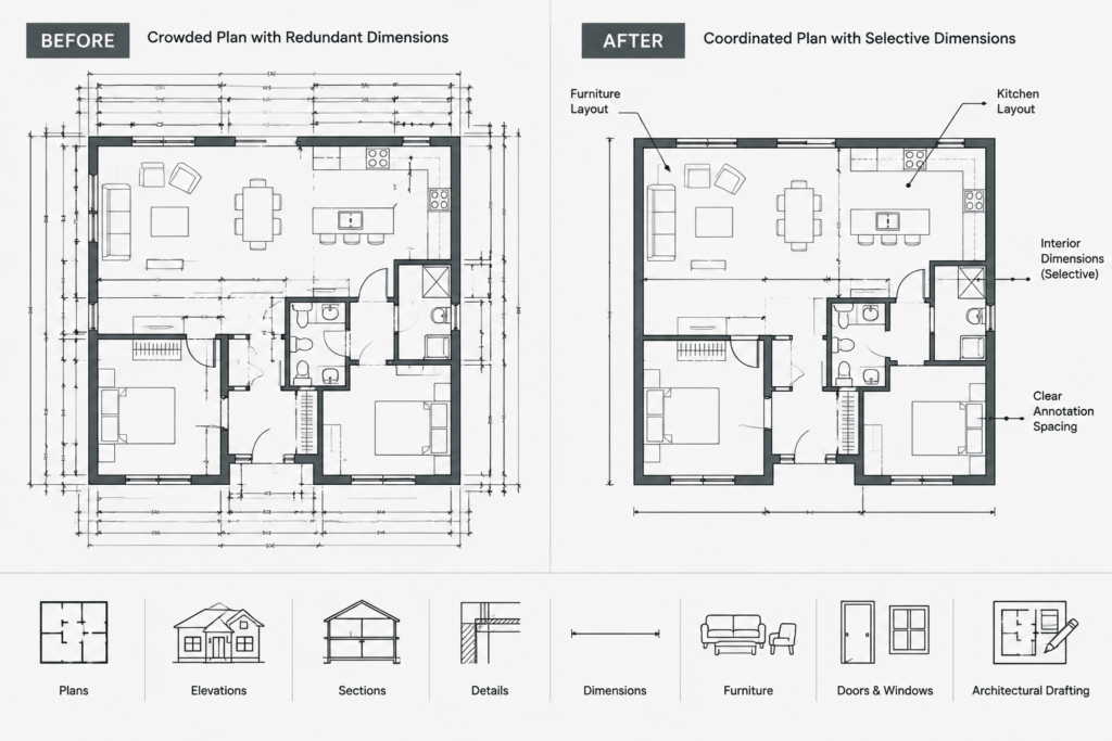
Dimension interior partitions selectively
Interior plans can become unreadable quickly if every room receives dimensions in both directions. Concentrate on partitions and elements that require positive location rather than dimensions that can be derived reliably from surrounding information.
Interior dimensions commonly help locate:
- Corridor boundaries and major circulation alignments
- Partitions that do not align with a grid or exterior wall
- Recesses, niches, shafts, and other plan offsets
- Fixed casework and built-in components
- Plumbing fixture groups when their position is controlled by the design
- Critical relationships between walls, doors, and fixed equipment
Movable furniture is usually better treated as layout information rather than as the primary basis for construction dimensions. If a furniture arrangement drives a partition location, dimension the partition or fixed architectural element instead of relying on the furniture block.
Avoid closed dimension chains
A closed dimension chain occurs when every segment and the overall distance are all treated as controlling values. Small drafting changes, rounding, or revised wall positions can then produce conflicting information.
Choose which dimensions control the layout and which dimensions are informational. In many situations, dimensions can progress from a stable reference toward successive elements, with an overall dimension used as a coordination check. Do not assume that adding more dimensions makes the drawing more accurate.
Repeated dimensions are another common source of conflict. If the same wall location appears on a floor plan, enlarged plan, interior elevation, and detail, determine which view should provide the controlling information. Other views can show only the dimensions needed for their specific purpose.
Use CAD dimension tools consistently
A coordinated dimension style helps maintain consistent text, arrowheads or ticks, spacing, units, and extension-line behavior. Project drawings should not depend on manually resized text or individually altered dimension objects.
Whether dimensions are managed through annotative objects or scale-specific styles, test them at the actual plotted sheet scale. A dimension that appears comfortable in model space may overlap adjacent notes or disappear into linework when viewed on the sheet.
Where the CAD workflow supports associative dimensions, attach dimensions to the intended geometry instead of placing them as disconnected graphics. Association can improve revision behavior, but it does not replace checking. A dimension may remain associated with the wrong endpoint after geometry is edited, copied, or replaced.
Avoid overriding displayed dimension values merely to make the text match an intended result. A text override can conceal incorrect geometry and may remain unchanged during later revisions. Correct the geometry or clarify the dimension reference whenever possible.
Separate dimensions from other annotation
Place dimensions on controlled layers so their visibility, lineweight, and plotting behavior can be managed independently. Exterior dimensions, interior dimensions, and dimensions used only in enlarged views may share a general system or use separate layers according to the project setup.
Do not use layer separation as a substitute for drawing judgment. Even well-layered dimensions can conflict visually with room names, door tags, wall tags, section marks, and revision clouds. Review the entire annotation field rather than editing each category in isolation.
Coordinate dimensions through revisions
Plan revisions should trigger a targeted dimension review. Moving a wall can affect adjacent room dimensions, opening locations, overall strings, enlarged plans, and related elevations. Deleting and redrawing geometry may also break associations that previously appeared correct.
After a significant revision:
- Check dimensions connected to moved or replaced geometry
- Compare overall dimensions with the revised plan extents
- Review door and window locations near changed partitions
- Check enlarged plans and interior elevations for repeated information
- Look for text overrides, detached dimensions, and empty dimension strings
- Plot or preview the affected sheets at their intended scales
Perform a final dimension audit
A final audit should evaluate both technical coordination and visual clarity. Trace the building from a few stable reference points and confirm that major walls and openings can be located without guesswork. Then look for redundant information that can be removed.
Ask whether each dimension answers a construction or coordination question. If it does not locate an element, verify a relationship, or clarify an otherwise ambiguous condition, it may not belong on the plan.
Clear architectural floor plan dimensioning depends on hierarchy, consistent references, and disciplined revision control. A smaller set of coordinated dimensions is generally more useful than a dense collection of measurements that compete with one another or repeat information from other views.


