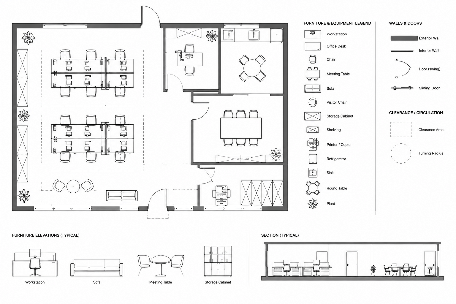
A furniture and equipment plan shows how movable items, casework, appliances, fixtures, and specialized equipment relate to the architecture of a space. It may support space planning, client review, pricing, procurement, installation, or construction coordination. Although it often begins with a floor plan, it should be managed as a coordinated drawing rather than a collection of decorative CAD blocks.
The exact scope varies by project. One drawing may show only furniture, while another combines furniture, fixtures, and equipment. Some projects separate owner-provided items from contractor-installed work. Before drafting, establish what the plan is expected to communicate and who will use it.
Define the drawing scope before placing blocks
A furniture plan and a formal furniture, fixtures, and equipment plan are not always interchangeable. A basic furniture plan may communicate room use and arrangement. A more detailed equipment plan can also coordinate item identities, utilities, mounting conditions, procurement responsibilities, and related schedules.
Prepare a short scope list covering the categories to be shown. Depending on the project, these may include:
- Loose tables, chairs, desks, sofas, beds, and storage pieces
- Built-in or freestanding cabinets and shelving
- Kitchen, laundry, office, retail, medical, or hospitality equipment
- Plumbing fixtures when they are relevant to planning and coordination
- Appliances and equipment requiring power, water, drainage, ventilation, or data
- Clearance zones, service access areas, and movable-panel paths
- Item tags, notes, and schedule references
Also decide which elements belong on other drawings. Lighting generally belongs on a reflected ceiling or lighting plan, while detailed power connections belong on the appropriate engineering drawings. The furniture plan can indicate coordination intent without duplicating every note from another discipline.
Start with a controlled architectural base
Use the current architectural floor plan as the base for the furniture drawing. When the office workflow allows it, reference the architectural background rather than copying walls, doors, and room geometry into the furniture file. A referenced base makes later architectural changes easier to identify and reduces the risk of maintaining conflicting copies.
Display enough background information to support placement decisions. Walls, columns, doors, windows, room names, and major built-ins are usually relevant. Excessive detail can make the furniture plan difficult to read, so reduce the visual strength of secondary background elements through the project’s layer and plotting standards.
Confirm drawing units before inserting any external block. A chair drawn in one unit system can appear plausible at the wrong scale if the mismatch is not caught immediately. Check a known architectural element, inspect the source block, and verify that the block geometry represents its actual intended size.
Organize furniture and equipment by meaningful categories
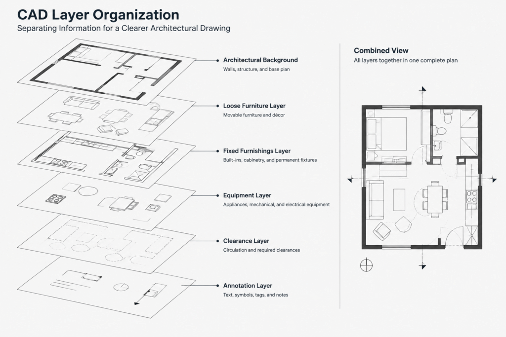
A single layer for every object may be quick at first, but it limits control later. Use categories that reflect how the drawing will be edited, displayed, scheduled, and issued. The layer names should follow the established office or project convention rather than an improvised system used only in one file.
| Drawing category | Typical content | Why separate it |
|---|---|---|
| Loose furniture | Chairs, tables, desks, beds, and movable storage | Allows layout studies and procurement items to be isolated |
| Fixed furnishings | Built-in benches, counters, shelving, and casework | Distinguishes construction-related items from movable pieces |
| Equipment | Appliances, machines, and specialty devices | Supports utility and installation coordination |
| Clearances | Access, operation, service, and movement zones | Permits review without plotting every guide on every issue |
| Tags and notes | Item identifiers, keynotes, and coordination notes | Provides separate control over annotation appearance |
| Existing or relocated items | Items retained, removed, or moved during renovation | Clarifies status and avoids ambiguous reuse assumptions |
Categories should not imply contractual responsibility unless that responsibility has been established. If ownership or installation responsibility matters, record it explicitly in the schedule, notes, or specifications used by the project team.
Prepare CAD blocks for reliable planning
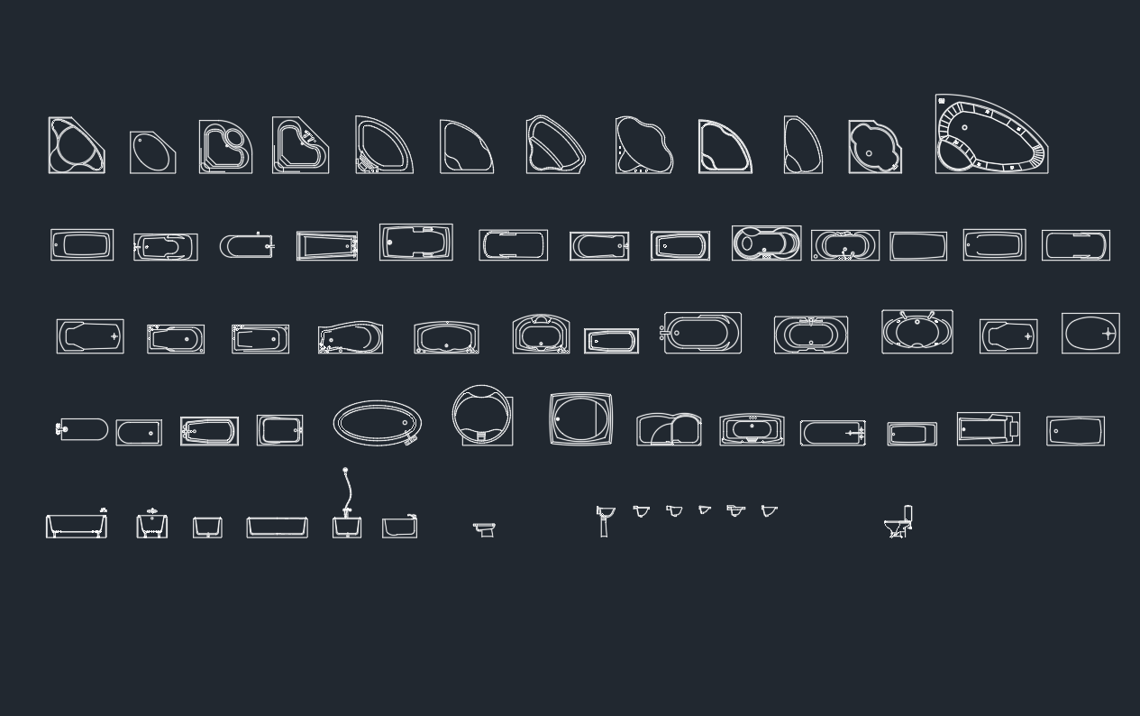
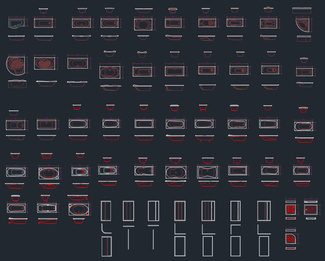
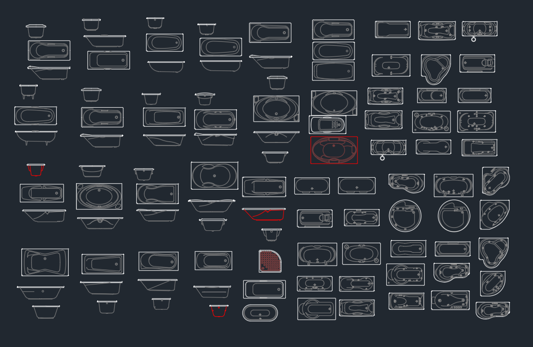
Use blocks that are clean, correctly scaled, and appropriate for the drawing view. Plan blocks should represent the footprint and important operating parts of an item without unnecessary product-level detail. Dense linework, tiny hardware, surface patterns, and repeated contours can make a floor plan noisy and increase file size.
Before adding a downloaded DWG block to the project library, inspect it in a separate working file. Check its units, layer content, linework, base point, nested objects, text, and overall extents. Remove irrelevant geometry and assign properties according to the office block standard. Do not assume a downloaded symbol represents a verified product or a code-compliant layout.
Choose a repeatable placement reference. A block may be based at its center, a back corner, a wall contact point, or another logical alignment location. The best choice depends on how the item is normally positioned. Consistency is more important than forcing every type of furniture to use the same base-point convention.
Develop the layout from circulation and use
Place the largest or least flexible items first. These may include beds, conference tables, workstations, major appliances, reception desks, or specialty equipment. Next, arrange supporting furniture and verify that doors, drawers, chairs, and movable panels can operate as intended.
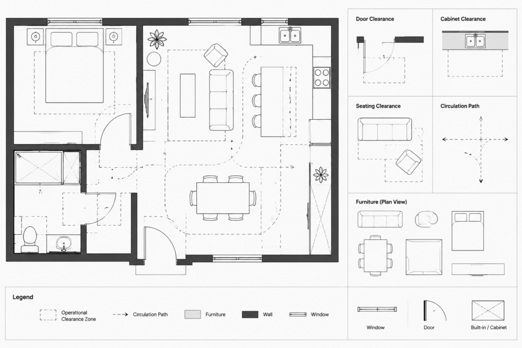
Do not evaluate a layout only by whether the outlines fit inside the room. Consider how occupants approach, use, clean, and maintain each item. Review the routes between doors and occupied areas, access to storage, sightlines where relevant, and conflicts with columns, glazing, radiators, floor boxes, or wall-mounted devices.
Clearance graphics can be valuable working tools. Use simple dashed boundaries, arcs, or separate blocks to represent chair pullback, door operation, equipment service access, or other functional zones. Keep these graphics on controllable layers so they can appear during coordination without overwhelming the issued plan.
Required clearances depend on the occupancy, equipment, jurisdiction, adopted rules, and project criteria. A generic CAD block should never be treated as proof that a room satisfies accessibility, egress, safety, or manufacturer requirements.
Tag items without overcrowding the plan
Tags connect plan symbols to schedules, specifications, selections, or procurement information. Establish a consistent identification method before tagging. An identifier might represent an item type, an individual asset, or a group of matching pieces. Mixing these approaches can produce duplicate or misleading quantities.
Keep tags outside dense linework when possible, and use leaders only where the association would otherwise be unclear. Repeated identical items may be tagged individually or identified as a group, depending on how quantities and locations are tracked. Whatever method is selected, apply it consistently across the drawing and schedule.
Block attributes can help store visible identifiers or other controlled information, but attributes are only as dependable as the editing process behind them. Check for copied blocks that retain an old tag, description, or status. A visually correct symbol can still carry incorrect data.
Coordinate plans, elevations, schedules, and utilities
The plan is only one view of the layout. Wall-mounted equipment, cabinets, mirrors, shelving, and stacked components may require interior elevations or sections to communicate mounting relationships and vertical clearances. Use the same item identifiers across every relevant view.
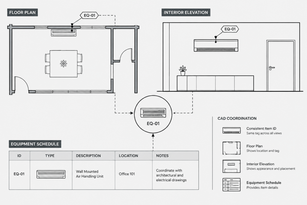
Equipment with utility needs should be compared with electrical, plumbing, mechanical, data, and architectural backgrounds. Check the actual item information available to the project rather than inferring connection locations from a generic block. Product selections may change, so unresolved requirements should be recorded and tracked instead of being silently assumed.
Schedules should be checked against the drawing, not generated or edited in isolation. Review identifiers, descriptions, quantities, room locations, status, and responsibility fields as applicable. If the project distinguishes new, existing, relocated, owner-furnished, or contractor-provided items, make those categories understandable in both the plan and schedule.
Use a repeatable quality-control pass
Complete a focused review before issuing the drawing. A useful furniture and equipment plan check includes:
- Confirming that the architectural background is current
- Checking block scale, orientation, and alignment
- Looking for objects placed inside walls, columns, glazing, or door swings
- Reviewing circulation, operation, and service zones
- Comparing item tags with schedules and related elevations
- Checking quantities for duplicated or missing items
- Verifying that utility-dependent equipment has been coordinated
- Reviewing existing, relocated, and new-item status
- Plotting at the intended sheet scale to test legibility
- Removing temporary notes, abandoned studies, and unused block definitions as appropriate
Run the review again after major plan changes. A shifted partition or revised door can invalidate a layout even when no furniture objects were intentionally edited.
Keep planning graphics separate from verified project information
Furniture blocks are excellent for testing arrangements and communicating design intent, but their linework should not be mistaken for verified product data. Generic blocks may omit handles, cords, controls, access panels, tolerances, or installation constraints. Even manufacturer-based drawings should be checked against the current selected item and project documentation.
A strong furniture and equipment plan combines clean CAD organization with practical spatial review. By controlling the architectural base, standardizing blocks, separating useful categories, coordinating tags and schedules, and checking functional clearances, the drawing becomes a dependable project tool rather than a visual arrangement of symbols.