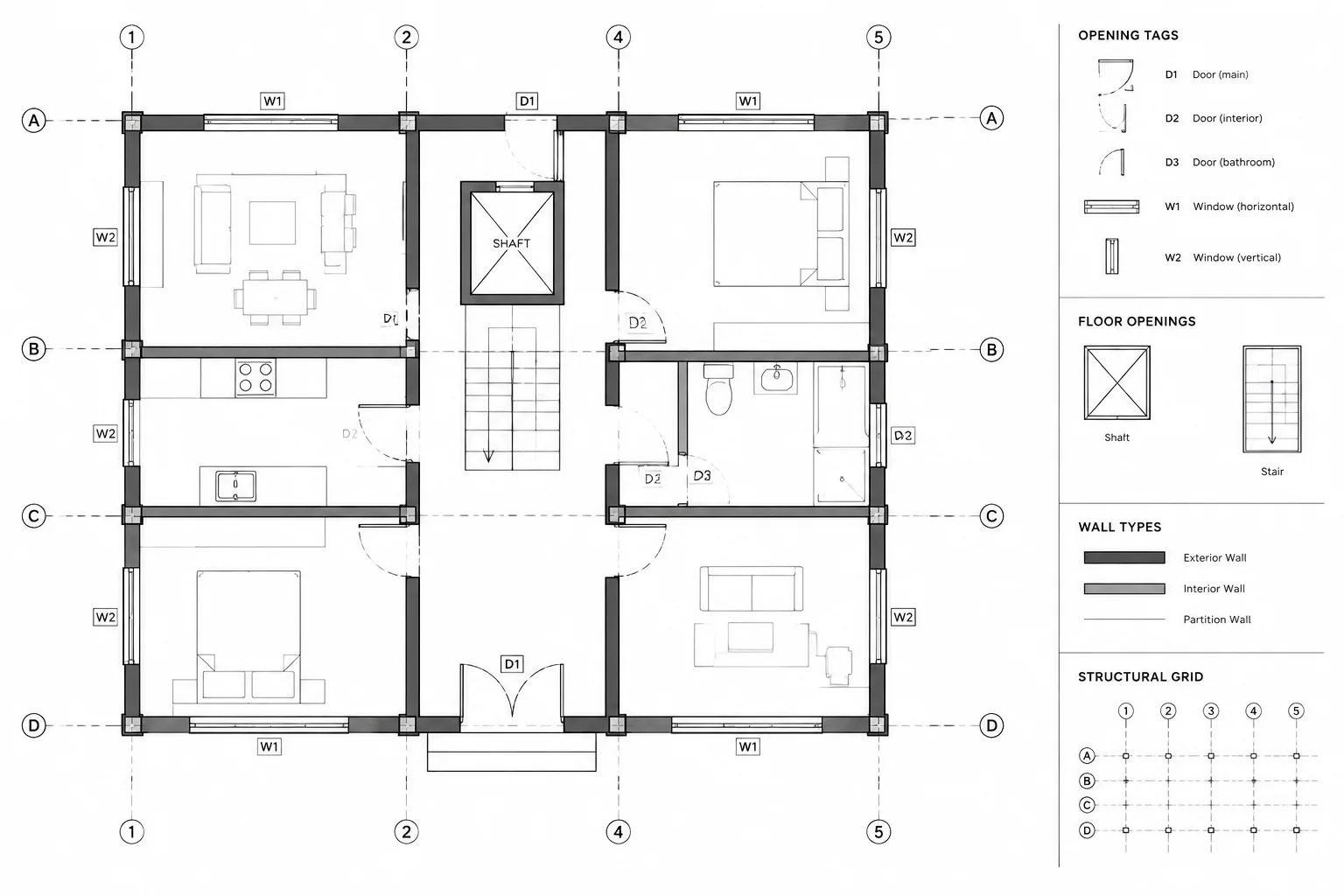
Floor opening coordination in architectural CAD is a drawing-management task as much as a drafting task. The geometry must remain connected to its purpose, requesting discipline, current status, and related views as consultant backgrounds and layouts change.
This guide presents a practical workflow for documenting architectural voids, shafts, equipment openings, sleeves, and service penetrations without treating unverified information as final. It also explains how to organize references, identifiers, layers, sections, and quality-control checks so that discrepancies can be found before an issue set is published.
Floor openings are easy to draw as rectangles, circles, or voids, but they are rarely simple coordination items. A single opening may affect the architectural plan, structural framing, reflected ceiling plan, room layout, fire-resistance strategy, waterproofing, and several building systems. If its location or purpose is unclear, the resulting conflict may not become visible until drawings are compared—or construction begins.
A reliable floor opening coordination workflow treats every opening as a tracked project element rather than an isolated line in a DWG file. The goal is to identify what passes through the floor, establish who controls the opening, and show consistent information wherever the condition appears.
Understand What the Opening Represents
Begin by separating major architectural voids from smaller service penetrations. Their documentation and approval paths are often different.
- Architectural openings: stair wells, atriums, access openings, floor hatches, and other voids directly related to spatial design.
- Vertical shafts: coordinated enclosures for elevators, ducts, pipes, utilities, or other systems.
- Equipment openings: floor voids associated with installed equipment or access requirements.
- Sleeves and penetrations: localized routes for pipes, conduits, ducts, drains, and similar services.
- Temporary or reserved openings: construction access or future-use zones that may later be infilled or modified.
Avoid using one generic symbol for every condition. A large framed opening, an enclosed shaft, and a small sleeve do not communicate the same design intent. Their boundaries, edges, supports, finishes, and discipline responsibilities may differ.
Establish Responsibility Before Drafting Details
The architect may coordinate and depict an opening without being the discipline that determines its final structural size or service requirements. Before developing the drawing, identify the source of the opening request and the party responsible for confirming it.
Useful coordination questions include:
- Which discipline requires the opening?
- Which consultant establishes the final clear area or sleeve size?
- Is the location controlled by a wall, room, grid, fixture, equipment item, or framing member?
- Does the floor edge require a curb, guard, enclosure, finish return, or other architectural treatment?
- Does the condition affect a rated assembly, waterproofed area, acoustic separation, or smoke-control strategy?
- Is the opening visible on more than one level or drawing type?
Answers should come from current project information and qualified team members. Do not infer structural acceptability, required protection, or code compliance from a downloaded block or a previous project detail.
Build a Stable CAD Base
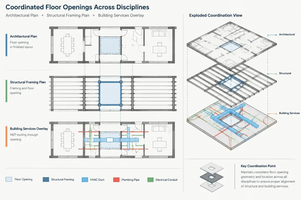
Coordinate openings against referenced discipline backgrounds whenever the project workflow allows it. Referenced files make later changes easier to identify and reduce the risk of tracing obsolete geometry into multiple drawings.
Before placing opening graphics, confirm that the architectural, structural, and building-system files share the correct units, origin, orientation, and floor level. An opening that appears aligned in one view can still be incorrect if a background was moved manually or inserted using the wrong settings.
Keep opening geometry on identifiable layers rather than placing it with walls, fixtures, or miscellaneous notes. A project may separate layers by opening type, status, or drawing purpose. Whatever structure is used, it should let the team isolate opening boundaries, tags, overhead graphics, and demolition information for review.
Create a Repeatable Opening Record
For openings that require active coordination, assign a unique identifier. The identifier can connect the plan symbol to a schedule, coordination register, detail, or consultant response. It also provides a stable reference when locations change.
A useful record may include:
- Opening identifier
- Floor or level
- Associated room, grid, or nearby reference
- Opening type and purpose
- Requesting discipline
- Nominal geometry or clear area, when verified
- Vertical extent
- Status, such as proposed, coordinated, revised, or removed
- Related drawing, section, detail, or equipment reference
- Outstanding confirmation or responsible party
The record does not need to become a large schedule on the construction sheets. It can be an internal coordination tool, provided that the information shown in issued drawings remains consistent with it.
Draft the Opening in Plan
Draw the true opening boundary whenever it is known. Avoid representing a coordinated void only with a centerline or marker, because reviewers need to understand the actual area affected. If the final boundary is still unresolved, clearly distinguish preliminary geometry from confirmed construction information.
Dimension the opening from stable project references. Grid lines, established wall faces, shaft boundaries, and other controlled geometry are generally more reliable than nearby furniture or movable equipment. Do not create redundant dimension chains that can disagree after a revision.
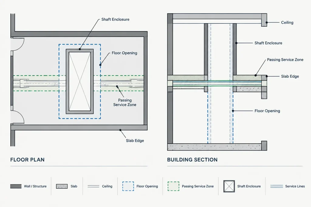
The plan should make the viewing relationship clear:
- An opening cut by the plan view should read as a primary plan element.
- An opening above or below the active level should use the project’s convention for beyond-view or overhead information.
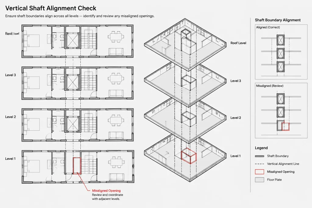
- A shaft continuing through several floors should be checked on every affected plan.
- An opening at a change in floor elevation should be supported by level information or a section reference.
Use concise notes. The plan should identify the condition and direct the reader to relevant information without repeating a full specification or coordination history.
Coordinate Plans, Sections, and Details
Plan geometry alone may not explain the vertical condition. Add a section or detail when the relationship among the slab, finish, curb, enclosure, ceiling, or passing service cannot be understood in plan.
| Drawing view | Primary information to verify |
|---|---|
| Architectural floor plan | Opening boundary, location, tag, adjacent walls, and circulation impact |
| Structural plan | Framing relationship, slab edge, support condition, and engineer-confirmed geometry |
| Reflected ceiling plan | Items passing through the ceiling, access needs, and visible coordination below the floor |
| Section | Vertical extent, floor buildup, curb or edge condition, enclosure, and level relationship |
| Detail | Construction interface, finish termination, protection, and discipline boundaries |
Do not draft structural reinforcement, proprietary firestopping, waterproofing assemblies, or equipment-specific requirements based only on appearance. These conditions require verified project details and appropriate technical input.
Check Openings Against Adjacent Architecture
A technically requested penetration can still create an architectural conflict. Review each opening in context rather than checking only whether it overlaps a structural element.
Walls and partitions
Confirm whether the opening must align with a shaft wall, remain within a service zone, or avoid intersecting a partition base. Check that wall thicknesses and finishes have not reduced the intended clear area.
Doors and circulation
Look for conflicts with door swings, thresholds, accessible routes, floor transitions, and maintenance paths. Required clearances and protection must be verified for the project rather than assumed from a typical layout.
Casework, fixtures, and equipment
Compare the opening with fixed cabinets, plumbing fixtures, appliances, access panels, and equipment footprints. A service opening may be correctly centered on equipment but inaccessible after adjacent construction is installed.
Wet and finished areas
Openings in roofs, terraces, kitchens, bathrooms, and other moisture-sensitive locations require careful coordination with slopes, drains, membranes, curbs, and finish layouts. The architectural drawing should identify the interface, while verified details establish how it is constructed.
Manage Revisions Without Losing History
Opening locations commonly change as equipment and routing develop. Do not erase an old opening and add a new one without recording the revision. Retain the identifier when the same opening moves, or establish a clear relationship between removed and replacement items.
When backgrounds are updated, compare them with the previous issue instead of relying only on visual memory. Review changes to opening edges, nearby framing, wall locations, equipment orientation, and level references. If consultants issue separate opening drawings, reconcile their identifiers with the architectural plans before publishing the next drawing set.
Run a Focused Quality-Control Review
Before issuing drawings, isolate or visually emphasize all opening-related layers and review the project floor by floor. A focused review often reveals omissions hidden in a dense plan.
- Every required opening has a clear purpose and owner.
- Identifiers are unique and readable.
- Locations are tied to stable references.
- Architectural and structural boundaries agree where coordination is complete.
- Vertical shafts align through all applicable levels.
- Plan, section, detail, and schedule information does not conflict.
- Removed openings are not still shown in another discipline file.
- Openings do not unintentionally conflict with walls, doors, ceilings, fixtures, or equipment access.
- Unresolved sizes or locations are clearly tracked and are not presented as verified.
- Plot previews show the intended lineweight and graphic hierarchy.
Treat Openings as Coordinated Objects, Not Loose Geometry
Effective floor opening coordination depends less on drawing complex shapes and more on maintaining reliable relationships. Each opening should connect a design need, a responsible discipline, a controlled location, and the views required to explain it.
A consistent identifier system, stable CAD references, disciplined layer use, and targeted quality control make changes easier to manage. They also help the project team distinguish confirmed construction information from unresolved coordination—one of the most important distinctions an architectural drawing can communicate.
Use a Clear Coordination Handoff
An opening request should move through a recognizable sequence from request to confirmation, drawing incorporation, and final review. This makes it easier to determine whether a discrepancy comes from outdated geometry, an unresolved consultant response, or an architectural drafting error.
- Request: Record why the opening is needed and which discipline initiated it.
- Locate: Relate the opening to controlled project geometry rather than temporary layout elements.
- Confirm: Obtain the required geometry and technical conditions from the responsible project team member.
- Document: Show the opening consistently in the relevant plans, sections, details, and coordination records.
- Review: Compare current backgrounds and check the opening against adjacent architecture before issue.
If confirmation is incomplete, the drawing status should communicate that condition. Preliminary geometry should not appear indistinguishable from coordinated construction information.
Review the Information, Not Only the Shape
A visual overlay can reveal misalignment, but it cannot confirm responsibility, approval, or technical suitability. A complete review also checks the opening identifier, purpose, level, source, status, and references to related views.
This distinction is especially important when several disciplines display similar boundaries. Matching linework may have been copied from the same outdated background, while different linework may reflect a legitimate change that has not yet reached every file. The coordination record provides the context needed to resolve the difference.
Preserve an Audit Trail for Changed Openings
When an opening moves or is removed, retain enough project history to explain what changed. Update the tracked status, reconcile the affected views, and check whether obsolete geometry remains in consultant references, demolition information, details, or schedules.
A disciplined audit trail reduces the chance that a superseded opening will reappear during a later drawing update. It also helps reviewers distinguish a relocated opening from an accidental duplicate.
Frequently Asked Questions
What is the difference between a floor opening and a penetration?
A floor opening generally describes a defined void in the floor construction, while a penetration describes a service or component passing through an assembly. Project terminology varies, so the drawings should identify the actual condition and its purpose rather than relying on a generic symbol.
Who determines the final size of an opening?
The responsible party depends on what creates the opening and what construction it affects. The architect may coordinate its location and architectural interface, but structural geometry, service requirements, equipment conditions, and protection details must come from the qualified project participants responsible for those systems.
Should every penetration receive an identifier?
Identifiers are most useful for items that require active coordination, repeated review, consultant confirmation, or references across several drawings. The project team should establish a consistent method that supports tracking without making the plans unnecessarily difficult to read.
How should an unresolved opening appear in CAD?
Use the project’s approved graphic and annotation conventions to distinguish preliminary information from confirmed work. Record the outstanding decision and responsible party so unresolved geometry is not mistaken for verified construction information.
What should be checked after a referenced background changes?
Compare the current reference with the previous issue and review opening boundaries, identifiers, nearby framing, walls, equipment, levels, and related sections or details. Confirm that the reference still uses the correct units, origin, orientation, and level relationship.
Can a typical detail be reused for a floor penetration?
A typical detail can help organize drawing information, but it should not be assumed to resolve every condition. Verify the assembly, passing service, finish interface, environmental exposure, and discipline responsibilities for the actual project before relying on it.