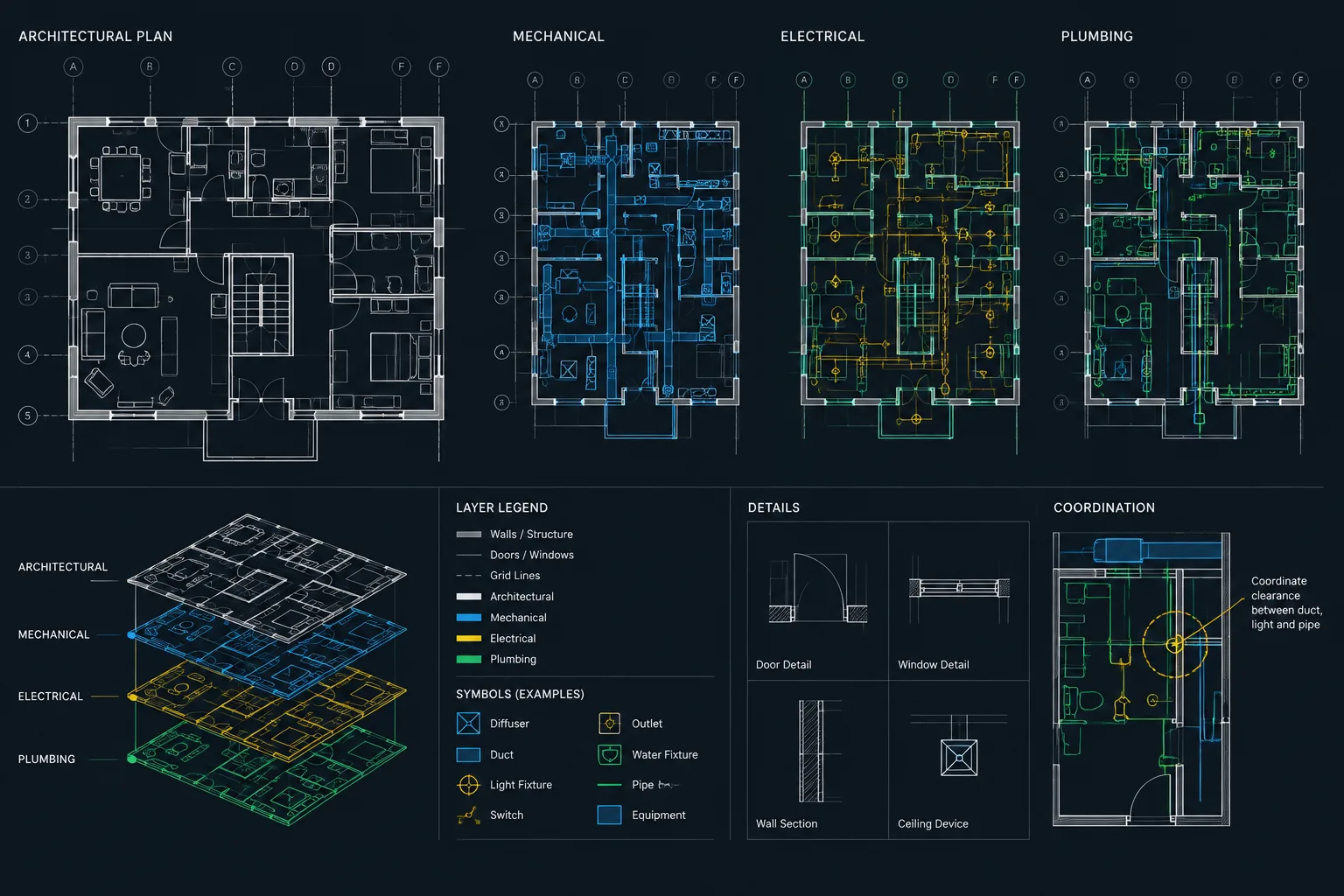
Coordinating architectural CAD plans with mechanical, electrical, and plumbing consultant drawings requires more than checking whether linework overlaps. The architectural team must establish a dependable reference background, confirm that incoming files align correctly, and distinguish actual design conflicts from differences in file setup or graphic representation.
This guide presents a practical MEP CAD coordination workflow for reviewing consultant DWGs while preserving discipline ownership. It focuses on reference management, systematic overlay review, issue tracking, revision control, and the consistent transfer of approved decisions into affected architectural drawings.
MEP CAD coordination is more than placing mechanical, electrical, and plumbing drawings beneath an architectural floor plan. Consultant files may arrive with different layer systems, drawing limits, origins, naming conventions, and levels of completeness. If those differences are not managed carefully, apparent conflicts can be mistaken for real ones, while important coordination issues remain hidden.
A dependable workflow keeps consultant drawings separate from the architectural model, verifies alignment before review, and records decisions without silently altering another discipline’s work. The goal is not to redesign consultant systems. It is to provide a clear architectural background, identify spatial conflicts, and incorporate agreed changes into the correct source drawings.
Begin with a controlled architectural background
Consultants should receive a deliberate background rather than an uncontrolled copy of the live architectural file. The background should contain the geometry and reference information required for coordination while excluding unnecessary presentation graphics, sheet annotations, and unrelated alternatives.
Before issuing the background, review the following items:
- Project origin, orientation, drawing units, and floor-level identification
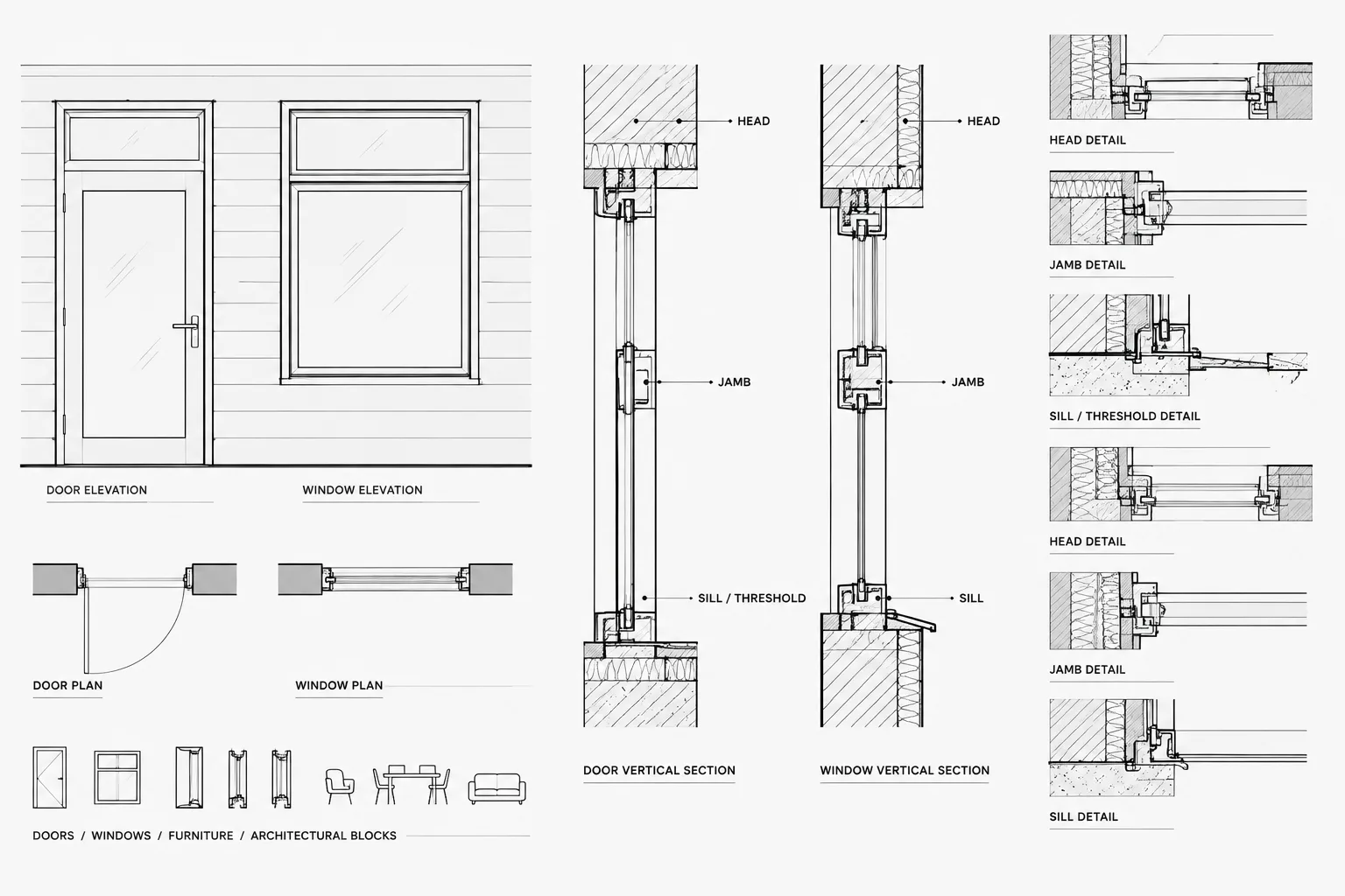
- Current wall, door, window, column, shaft, stair, and major ceiling geometry
- Room names or numbers needed for system coordination
- Relevant grids and architectural reference points
- Existing construction and demolition information when applicable
- File name, issue date, and revision status
Decide whether dimensions and notes belong in the shared background. Some consultants need selected dimensions for context, but excessive annotation can obscure system layouts. Geometry should remain the primary coordination reference.
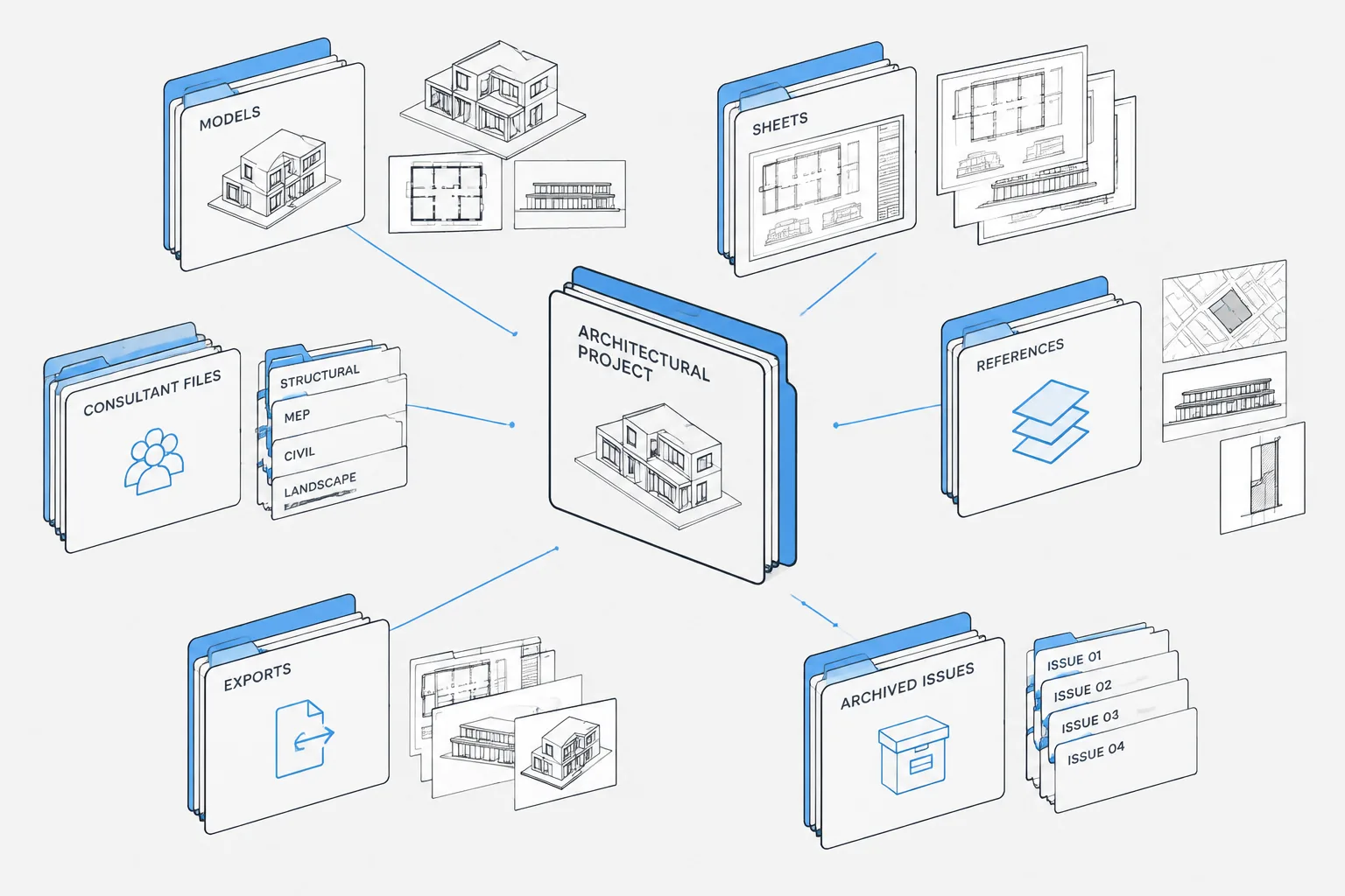
Retain an archived copy of every issued background. Without an issue record, it becomes difficult to determine whether a consultant worked from the current architectural plan or an earlier layout.
Check incoming consultant DWGs before attaching them
Do not immediately insert a received DWG into the working architectural file. Open or inspect it separately first. A preliminary check can reveal unit problems, remote objects, broken references, unexpected layouts, or geometry placed far from the intended project area.
Confirm file identity and status
Verify the discipline, floor or area, issue status, and date. File names alone may not reliably indicate whether a drawing is current. If the consultant package contains multiple files, identify which files are model backgrounds and which are sheets, details, diagrams, or supporting references.
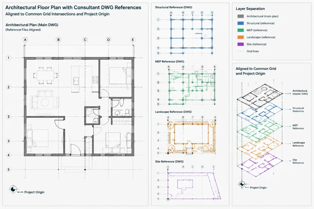
Verify units, origin, and orientation
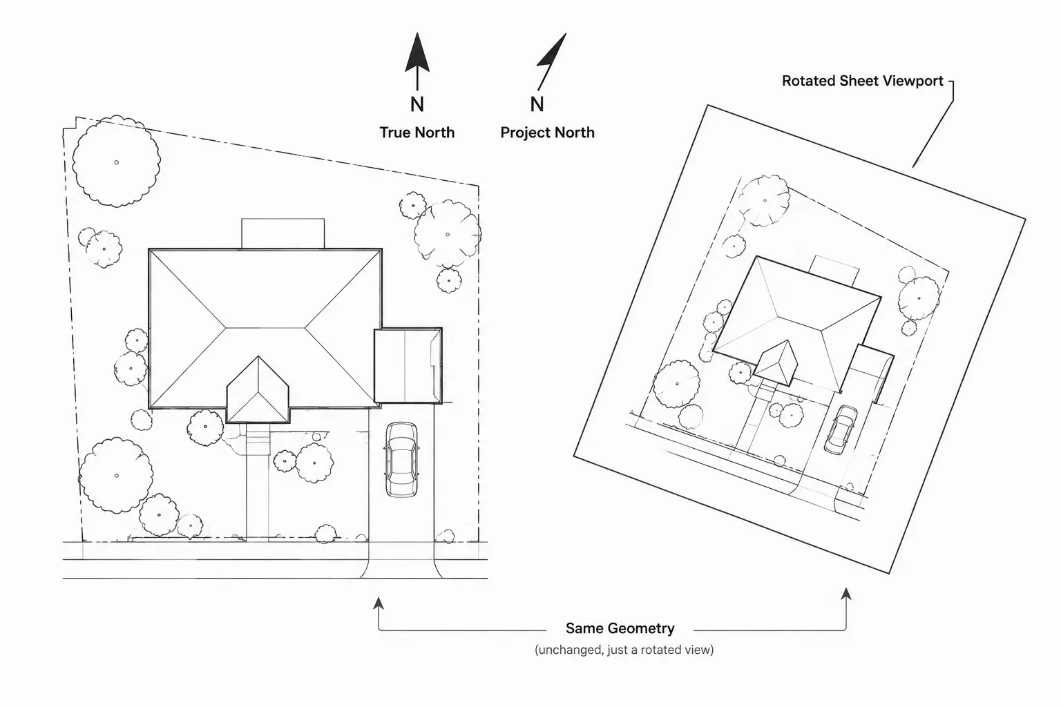
Confirm that the consultant file uses the expected drawing units and project reference system. Compare known grids, exterior corners, shafts, or other stable control points. Avoid moving, rotating, or scaling consultant geometry merely to make it appear aligned. That can conceal a source-coordinate problem and make the next update difficult to replace.
If adjustment is genuinely required, document it and request a corrected source file. A temporary transformation used for review should be clearly identified and should not become the permanent coordination method.
Review external references and drawing extents
Determine whether the consultant file depends on additional references. Missing architectural backgrounds or nested discipline files can make the received drawing appear incomplete. Also check for distant text, stray lines, or unused geometry that expands the drawing extents and complicates navigation.
Attach consultant drawings as references
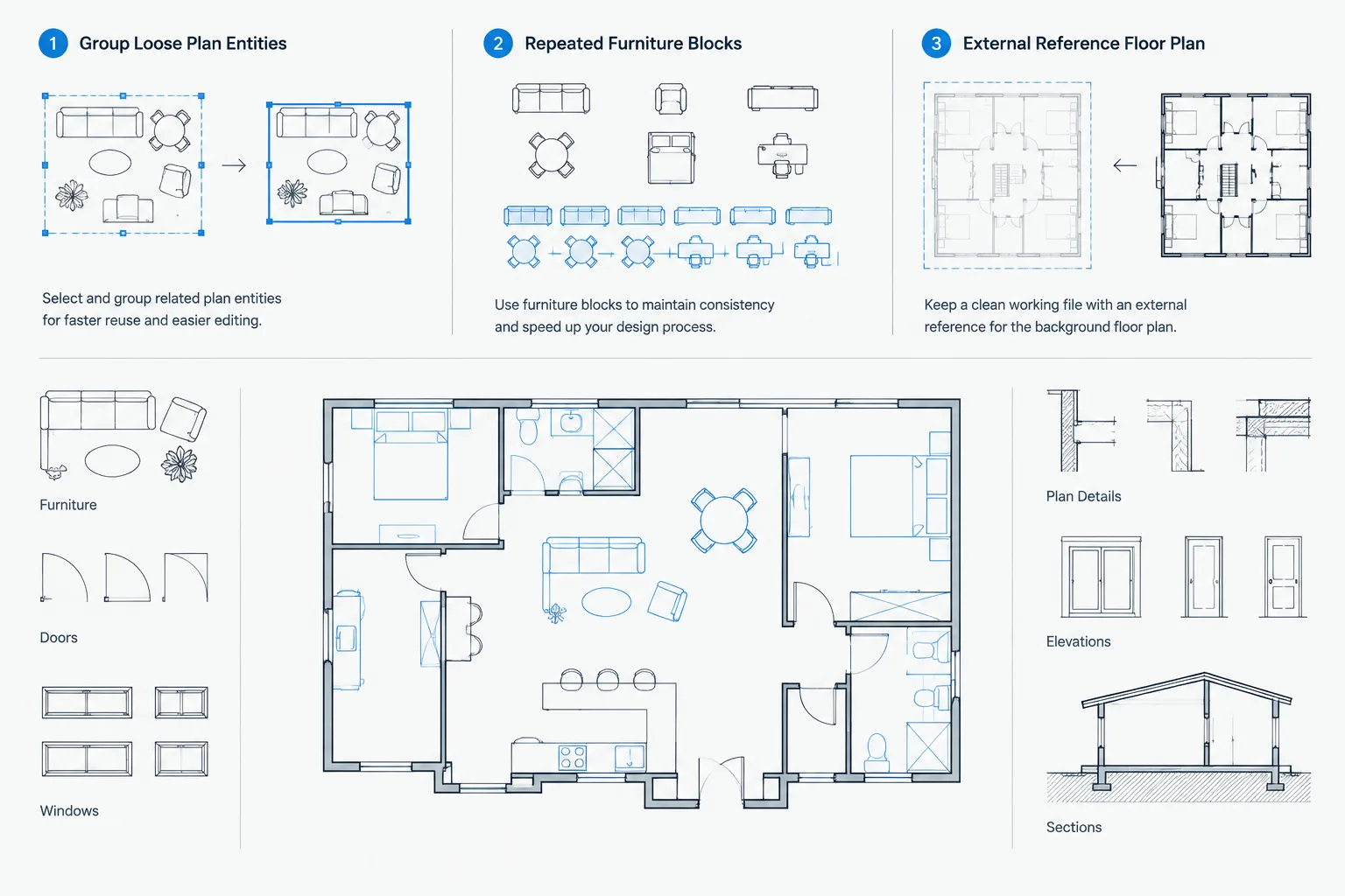
For ongoing coordination, attach each consultant DWG as an external reference rather than copying its objects into the architectural model. Referencing preserves ownership boundaries and allows an updated file to replace the previous version without rebuilding the overlay.
Use a predictable folder and naming structure. Separate received consultant files from files created by the architectural team, and avoid editing the received originals. If a file must be cleaned for technical reasons, preserve the original and label the processed copy clearly.
Keep each discipline independently controllable. Mechanical, electrical, plumbing, structural, and other systems should not be merged into one anonymous overlay. Independent references make it easier to isolate conflicts and determine who owns the affected geometry.
Create review displays instead of changing source graphics
Consultant layers are often organized for that discipline’s production needs, not for an architectural coordination view. Use reference-layer controls, saved layer states, or dedicated review files to create readable overlays without permanently changing the consultant drawing.
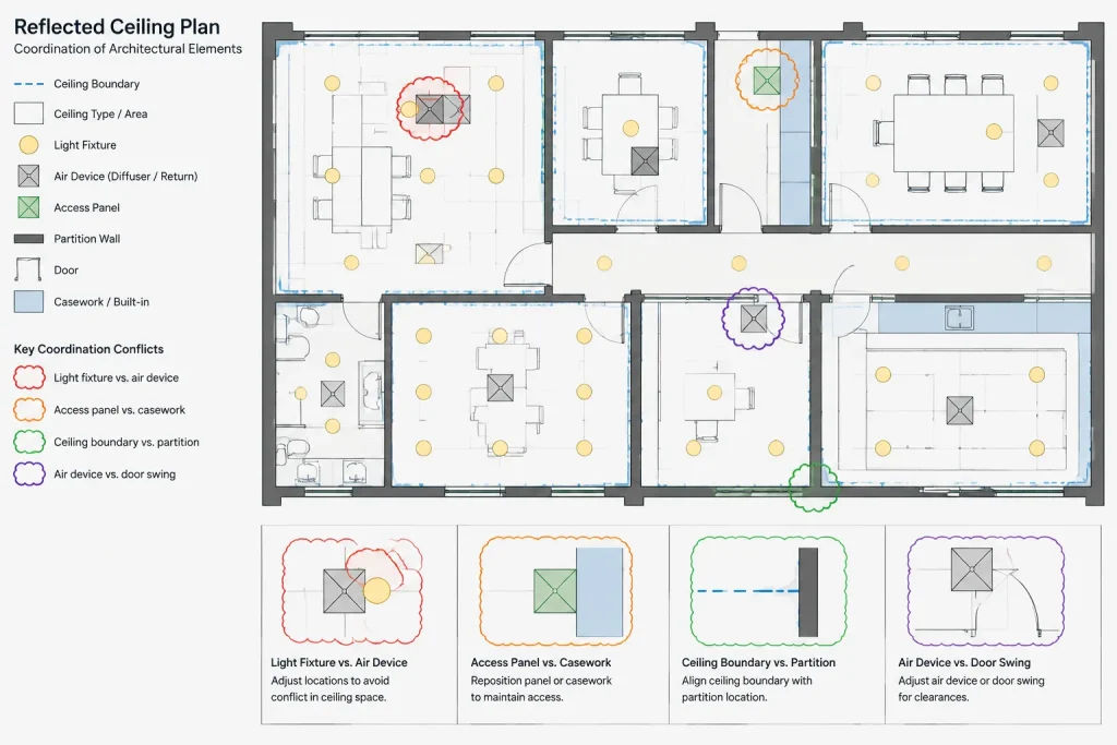
A useful review display typically emphasizes:
- Architectural walls, openings, rooms, ceilings, shafts, and fixed equipment
- The consultant system currently under review
- Control information such as grids and reference points
- Markup identifying questions, conflicts, and required decisions
De-emphasize information that does not support the current review. For example, an electrical review may require devices and equipment locations to remain prominent while unrelated notes or diagram graphics are reduced. Review one discipline or system at a time before examining the combined overlay.
Review coordination by architectural zone
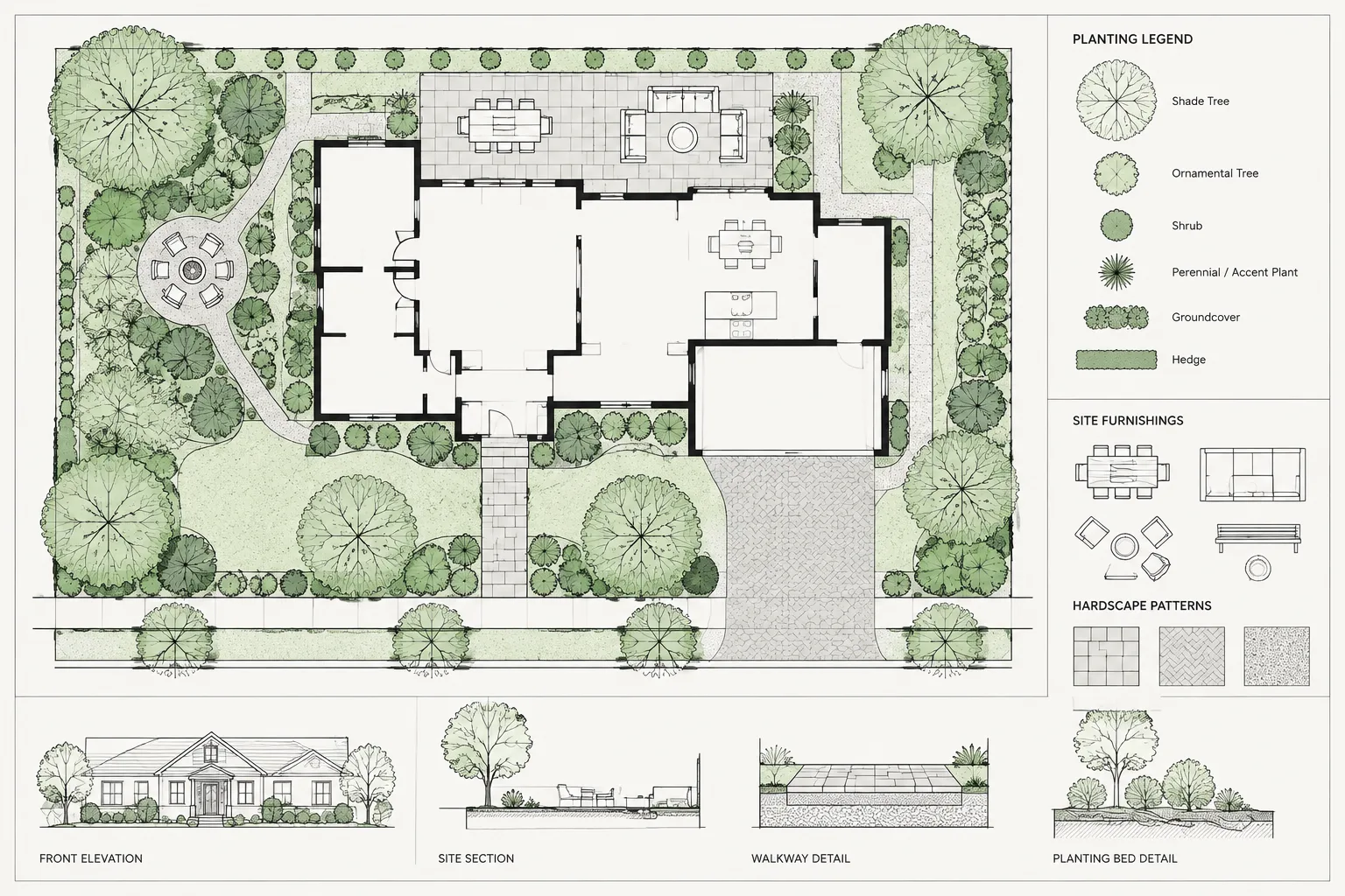
Scanning an entire plan randomly makes omissions likely. Divide the building into repeatable review zones such as rooms, circulation areas, service spaces, ceiling zones, exterior walls, roof areas, and vertical shafts. Then check each zone against a consistent set of questions.
| Review area | Architectural items to compare | Typical coordination question |
|---|---|---|
| Walls and partitions | Wall location, thickness, openings, and rated or specialty designations shown by the project team | Does equipment or distribution cross a wall where an opening has not been coordinated? |
| Doors and circulation | Door swings, frames, access routes, and movable elements | Does a device, fixture, or unit interfere with operation or intended circulation? |
| Ceilings | Ceiling boundaries, soffits, access panels, lights, diffusers, and other visible devices | Are visible elements arranged consistently with the ceiling design and available space? |
| Shafts and service spaces | Enclosure boundaries, access locations, and floor openings | Do the systems fit within the coordinated architectural zone without relying on outdated boundaries? |
| Casework and equipment | Cabinets, counters, appliances, plumbing fixtures, and owner equipment | Are required connections located relative to the current architectural arrangement? |
| Exterior and roof | Wall penetrations, louvers, screens, roof openings, and equipment zones | Has the architectural impact of each visible or weather-exposed component been addressed? |
These checks identify drawing conflicts, but they do not replace discipline-specific design, engineering, code review, manufacturer requirements, or field verification.
Distinguish geometry conflicts from information conflicts
Not every coordination issue is a physical clash. Some are information mismatches that can produce equally serious drawing errors.
- Geometry conflict: Two objects occupy incompatible space or obstruct intended movement.
- Reference conflict: Disciplines use different grids, room numbers, levels, or background revisions.
- Scope conflict: It is unclear which discipline must show, specify, or locate an item.
- Representation conflict: The same item appears differently in plan, ceiling plan, elevation, section, or schedule.
- Status conflict: One drawing shows an item as new while another shows it as existing, removed, or unresolved.
Classifying the issue helps route it to the correct person and prevents lengthy discussions caused by vague markup.
Record issues without drawing over the answer
Use a coordination log or organized markup process instead of immediately changing architectural geometry to accommodate every consultant line. Each issue should identify the location, affected disciplines, drawing or view, concise description, responsible party, and current status.
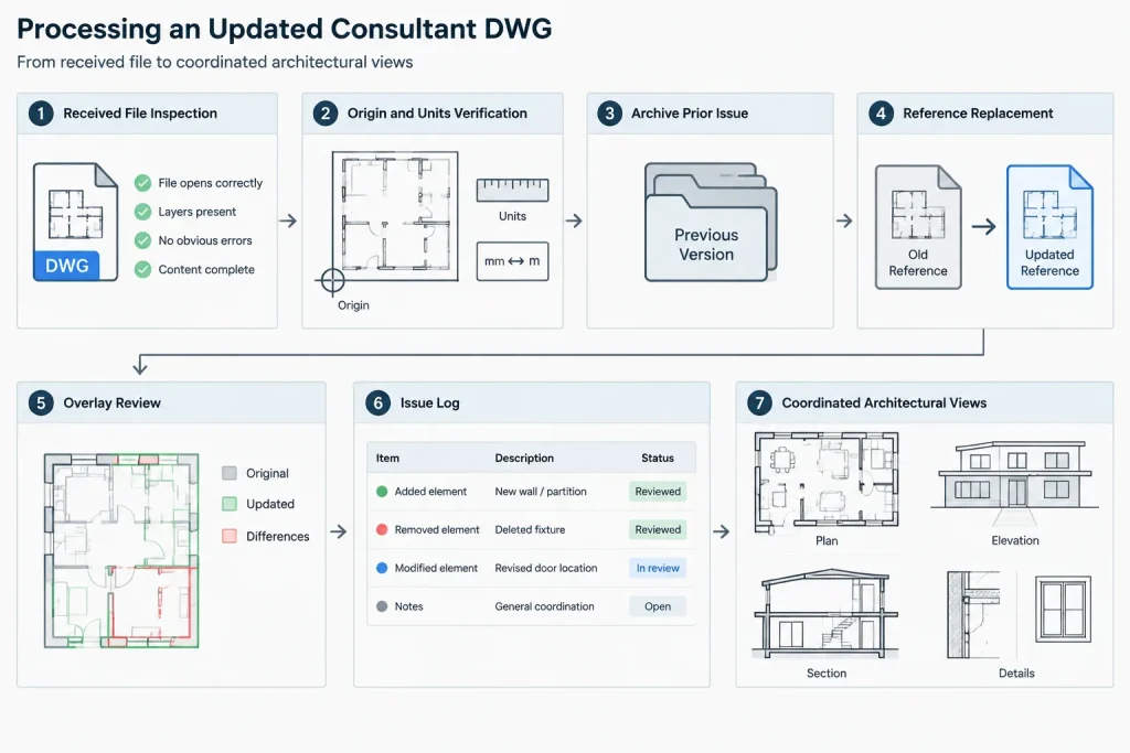
Markups should separate questions from approved changes. A cloud or note indicates that an issue exists; it does not establish the final design solution. When a decision is reached, update the responsible source drawing and record the response. Avoid leaving important resolutions only in email, meeting notes, or temporary review files.
Process updated files as replacements, not additions
When revised consultant drawings arrive, archive the previous set and replace references through a controlled file process. Do not attach the new drawing beside the old one without a clear comparison plan. Confirm that the updated file still uses the expected units, origin, orientation, and reference structure.
Compare the update with the prior issue and focus on more than the items previously marked. Consultant changes can affect room layouts, ceiling coordination, access locations, equipment clearances, openings, and elevations elsewhere in the drawing.
After accepted decisions are incorporated, verify related architectural views. A shifted service opening shown on a floor plan may also affect an elevation, section, roof plan, ceiling plan, detail, or schedule. Coordination is complete only when the change is reflected consistently across the drawing set.
Maintain discipline ownership
A clean CAD workflow respects who owns each piece of information. The architectural team should not quietly redraw consultant systems to make a coordination sheet look correct. Similarly, consultant backgrounds should not become accidental substitutes for the current architectural model.
Keep received references read-only where practical, document file transformations, and return discrepancies to the authoring discipline. This approach creates a traceable exchange process and reduces the risk that an unverified overlay becomes treated as approved project information.
A concise MEP CAD coordination checklist
- Issue a controlled and archived architectural background.
- Inspect incoming files before attaching them.
- Confirm units, origin, orientation, floor, and issue status.
- Reference consultant drawings rather than copying their objects.
- Keep disciplines independently visible and manageable.
- Create purpose-specific overlay displays for review.
- Check plans systematically by zone and building element.
- Classify and log conflicts instead of making undocumented edits.
- Archive previous consultant issues before processing replacements.
- Carry accepted changes into every affected architectural view.
Effective MEP CAD coordination depends on controlled backgrounds, reliable alignment, readable overlays, and documented decisions. A disciplined process makes consultant updates easier to review and helps the architectural drawing set remain internally consistent without blurring responsibility between project teams.
Turn overlay review into a decision process
A coordinated overlay is useful only when the team can convert visible discrepancies into clear actions. Review comments should explain what is inconsistent, where it occurs, which drawings are affected, and which discipline needs to respond. This is more useful than a general note stating that systems must be coordinated.
During review, separate issues that prevent reliable comparison from issues involving the design itself. A file with an uncertain origin, incorrect background, or unclear revision status should be corrected before its apparent clashes are treated as project conflicts. Otherwise, the team may spend time resolving problems created by file setup rather than by the proposed work.
Prioritize issues by dependency
Some decisions influence many downstream drawings. Shaft boundaries, ceiling arrangements, equipment locations, service openings, and fixed architectural elements can affect several plans, sections, elevations, details, and schedules. Resolve these foundational relationships before refining isolated graphic discrepancies.
When an issue affects several disciplines, identify the information needed from each participant rather than assigning a vague coordination note to the entire team. The architect may need to clarify an enclosure or finish condition, while the consultant may need to confirm routing, access, or equipment requirements. The final decision should then be incorporated by each responsible author into the appropriate source file.
Use closure criteria for coordination comments
A comment should not be considered closed merely because it was discussed. Closure means that the responsible discipline has provided a clear response, the accepted change appears in the current source drawing, and related architectural views have been checked for consistency.
If a temporary assumption is required to keep drafting work moving, label it as unresolved and retain it in the coordination record. This prevents a provisional graphic adjustment from being mistaken for an approved design decision.
What a reliable coordination handoff should communicate
At each exchange, the receiving team should be able to determine what file was issued, what architectural background it was based on, what changed, and which questions remain open. Consistent file identification and a brief issue summary make the drawing package easier to evaluate without relying on memory or informal conversations.
The result of MEP CAD coordination is not a single perfect overlay. It is a traceable sequence of reviewed files and documented decisions in which architectural and consultant drawings remain aligned, readable, and controlled by their respective authors.
Frequently Asked Questions
Should MEP consultant objects be copied into the architectural CAD file?
For ongoing coordination, consultant drawings are generally better maintained as separate external references. Copying objects into the architectural model can obscure ownership, create duplicate information, and make later consultant updates harder to process.
What should be checked when a consultant DWG does not align?
Check the drawing units, project origin, orientation, floor or area identification, reference structure, and background revision before moving or scaling anything. An unexplained manual adjustment can hide the real source of the mismatch.
How can a dense MEP overlay be made easier to review?
Isolate the discipline or system being reviewed, emphasize relevant architectural geometry, and de-emphasize unrelated notes and graphics. Review by room, zone, or building element rather than attempting to interpret every system simultaneously.
Who should edit geometry when a conflict is found?
The discipline that owns the affected information should revise its source drawing after the team agrees on the solution. Architectural staff should avoid silently redrawing consultant systems, and consultants should receive current architectural backgrounds rather than reconstructing them independently.
When is a coordination issue considered resolved?
An issue is resolved when the responsible party has answered it, the approved change appears in the current source file, and every related architectural view or schedule has been reviewed for consistency.
Does a coordinated CAD overlay replace engineering or code review?
No. An overlay can reveal spatial and documentation conflicts, but it does not replace professional discipline design, applicable code evaluation, manufacturer requirements, or field verification.