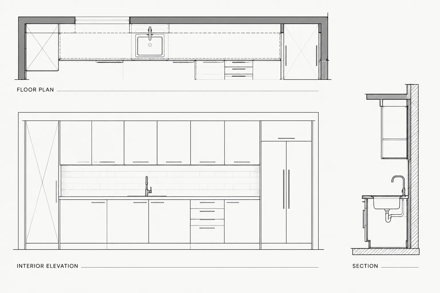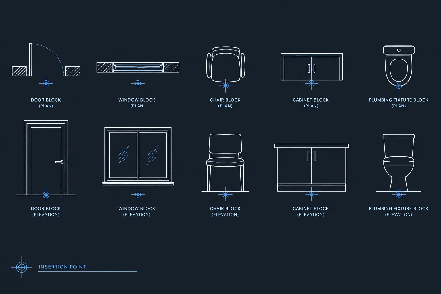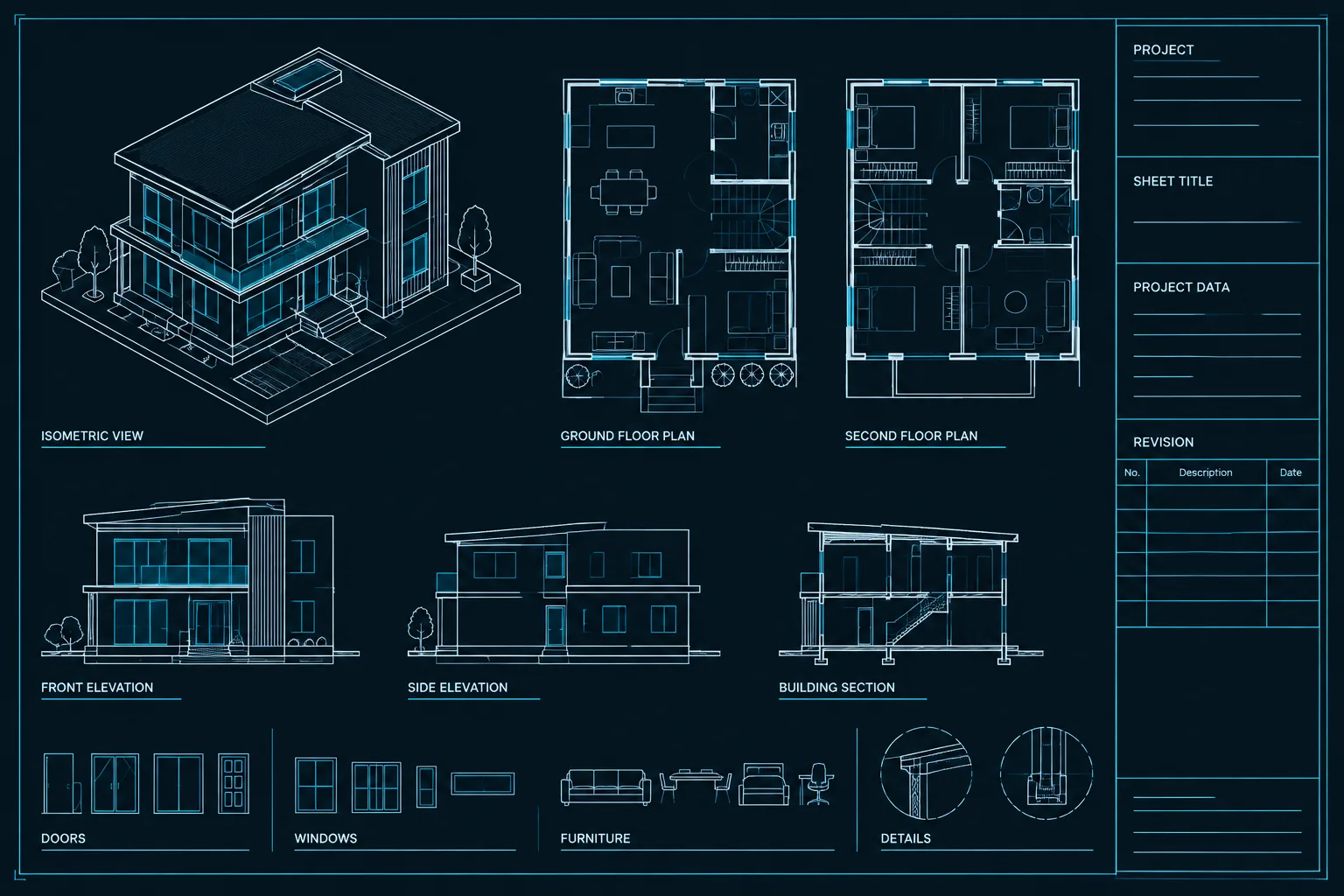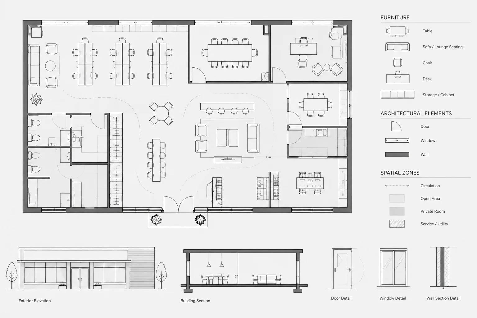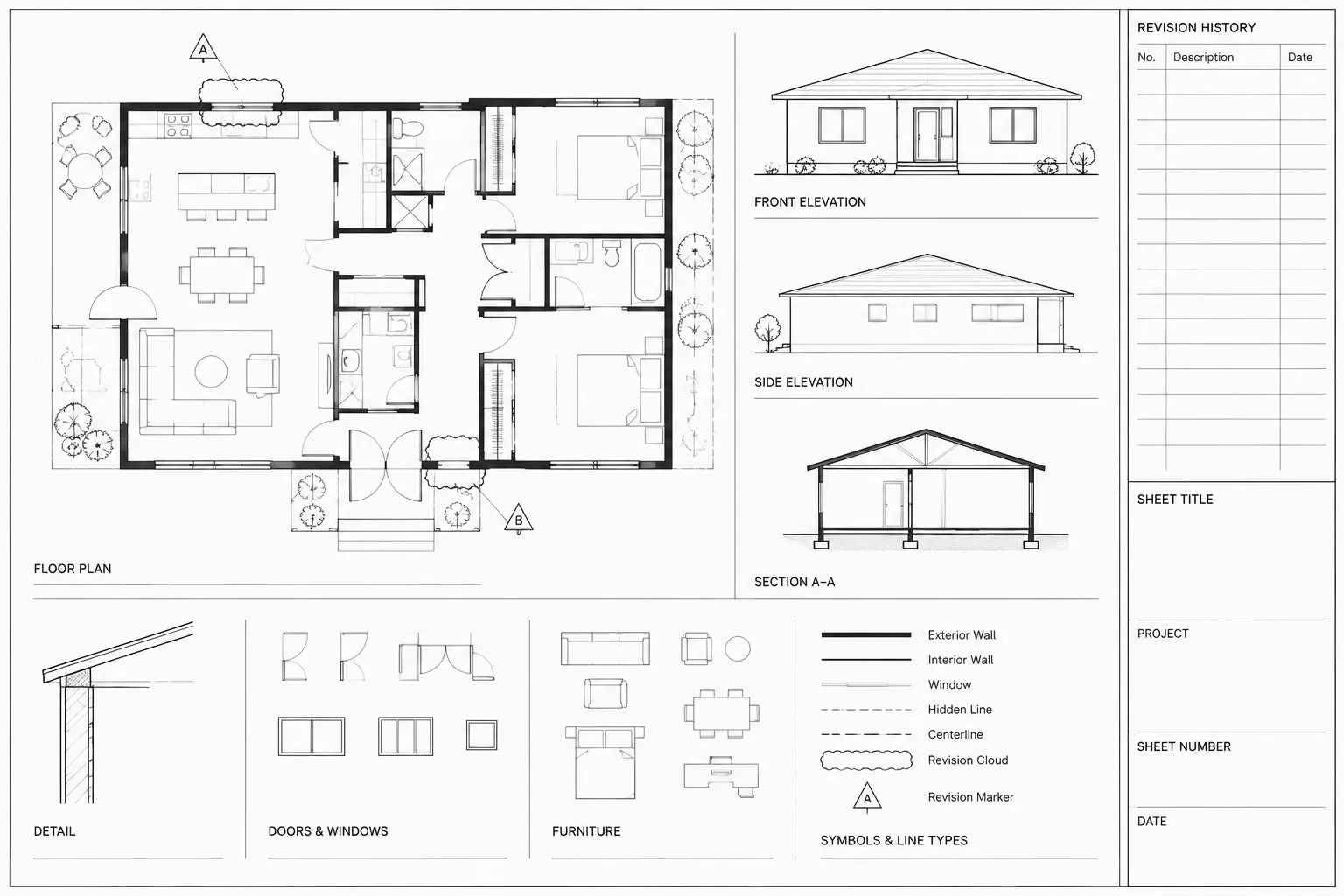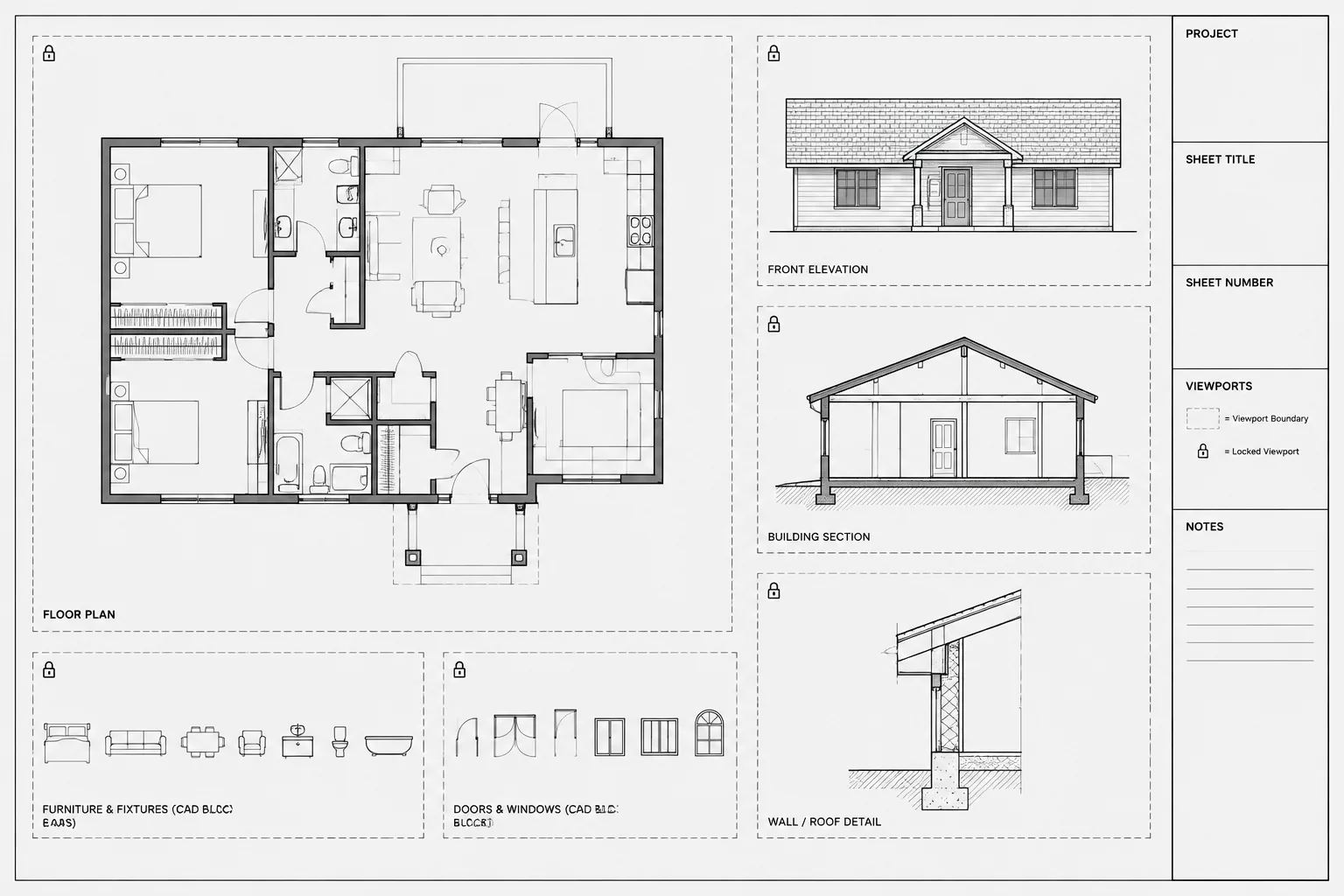
Building a dependable window schedule requires more than arranging marks and dimensions in a CAD table. The schedule must remain coordinated with plans, elevations, type drawings, wall details, glazing information, and project revisions.
This guide explains how to define the schedule’s role, choose an identification method, organize useful fields, evaluate different CAD production methods, and check the completed schedule across the architectural drawing set. The goal is a traceable documentation system rather than an isolated table.
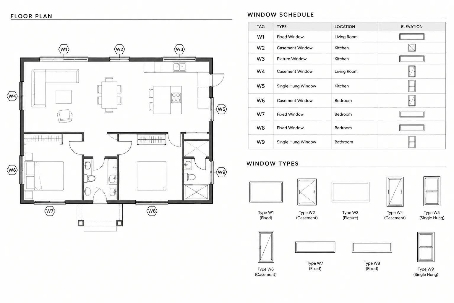
A window schedule in architectural CAD is more than a list of opening sizes. It is a coordination tool connecting window tags on plans and elevations with type drawings, wall conditions, details, specifications, and product selections. When these sources disagree, installers and reviewers may be left to determine which information is current.
A reliable schedule begins with a clear information strategy. The project team should decide what the schedule controls, what belongs in supporting drawings or specifications, and how changes will be checked. The following workflow applies whether the schedule is drawn directly in a DWG file, generated from attributed blocks, or maintained through another project data source and placed on a CAD sheet.
Define the purpose of the window schedule
Before creating columns, establish how the schedule will be used. A small project may need a compact list of marks, operation types, and opening information. A more complex project may require coordination of glazing, frame materials, hardware groups, acoustic criteria, security requirements, or related details.
A schedule should identify windows clearly without attempting to reproduce every requirement found elsewhere. Product performance, testing criteria, installation requirements, and detailed material descriptions are often better handled in specifications or referenced details. Avoid filling the schedule with assumptions simply because a field is available.
Establish the window identification system
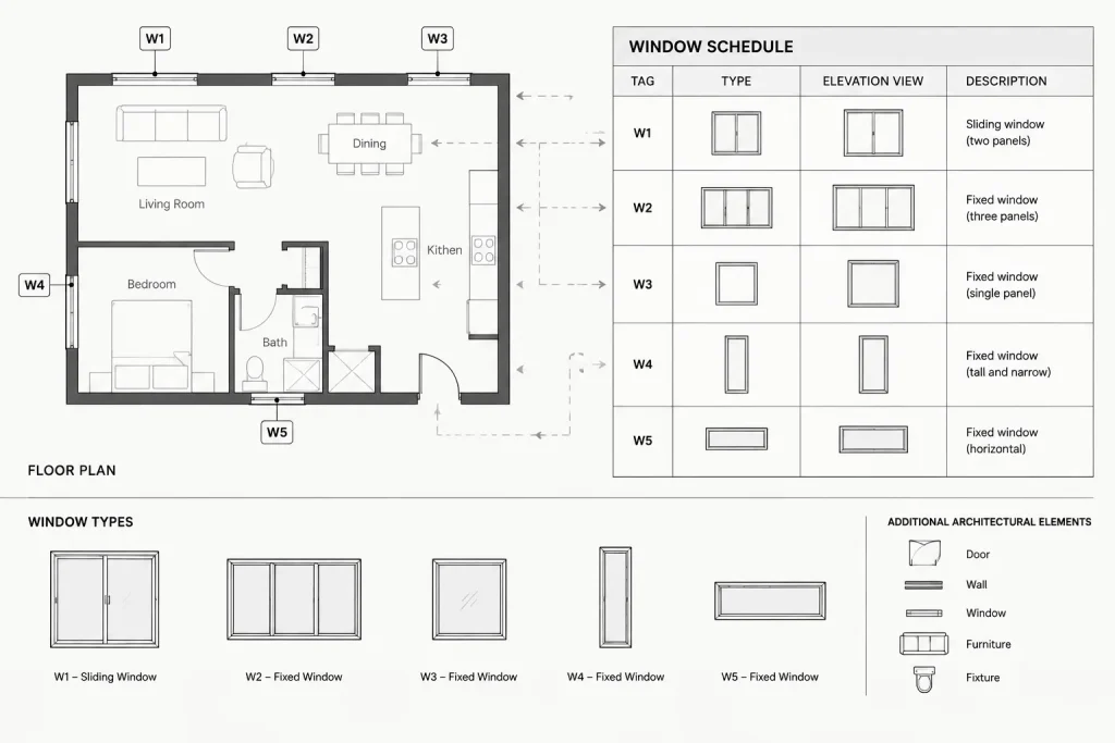
Each scheduled window or window type needs a unique mark. The marking method should match the project’s documentation approach.
- Type-based marks: Multiple windows with the same documented configuration share one type mark.
- Instance-based marks: Each physical window receives its own identifier, even when several units are similar.
- Grouped assembly marks: A multi-unit composition is identified as one assembly, with individual components explained in a type elevation or detail.
Type-based scheduling can keep drawings concise, but it requires the team to confirm that repeated windows are genuinely interchangeable. Instance-based scheduling provides more location-specific control but creates additional records to maintain. A hybrid system may be appropriate when typical units repeat and selected openings have unique conditions.
Use one mark consistently across plans, exterior elevations, interior elevations where applicable, type drawings, details, and the schedule. Avoid reusing a deleted mark for a different window during the same project unless the team has a deliberate renumbering procedure.
Select schedule fields deliberately
Schedule columns should support purchasing, documentation, and coordination without duplicating uncontrolled information. Common fields may include the following:
| Field | Coordination purpose | Common caution |
|---|---|---|
| Window mark | Connects the schedule to drawing tags | Marks must remain unique within the chosen system |
| Type or operation | Identifies the documented window configuration | Use consistent terminology throughout the set |
| Width and height | Records the intended scheduled size basis | State whether dimensions describe units, openings, or another reference |
| Frame material or series | Separates materially different assemblies | Do not imply an unverified product selection |
| Glazing designation | Links the opening to glazing information | Coordinate with specifications and elevations |
| Head, jamb, and sill references | Directs users to installation conditions | Confirm that references match the actual wall condition |
| Remarks | Captures limited exceptions | Do not turn the remarks column into an uncontrolled note list |
The meaning of dimensional fields must be explicit. A listed width could refer to a nominal unit, frame dimension, rough opening, or masonry opening. Those values are not automatically interchangeable. Add a clear schedule heading or general note that identifies the dimension basis, then verify it against the project’s details and selected system.
Build the schedule structure in CAD
Create the schedule using the office’s established table, text, layer, and plotting conventions. The specific production method matters less than maintaining a single dependable source of information.
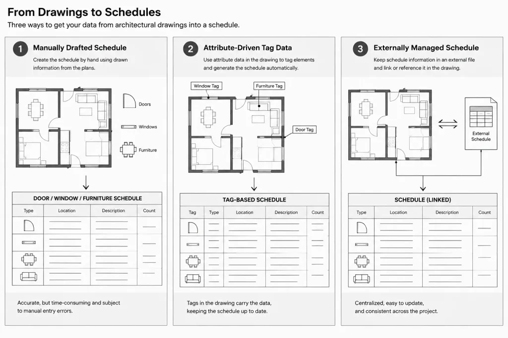
Manually drafted schedule
A manually edited CAD table is straightforward and visually controllable. It works well when the number of records is limited and changes are carefully reviewed. Its main weakness is that window tags and schedule rows are not inherently connected, so omissions and duplicate marks require manual detection.
Attribute-driven schedule
Window tags or planning blocks may contain attributes that can be extracted into a table. This can reduce repeated typing, but only if attribute names, values, and block definitions are managed consistently. Extraction does not validate design intent; it can reproduce incorrect or incomplete data just as efficiently as correct data.
Externally managed data
Some teams maintain window information in a spreadsheet, database, or another design platform and use it to support the CAD schedule. Establish which file is authoritative, who may edit it, and how updates enter the drawing set. Uncontrolled edits in both the DWG and the external source can quickly create conflicting versions.
Coordinate schedule marks with plans and elevations
Begin with a systematic review of every exterior opening and any scheduled interior windows. Move through the plan in a consistent direction or by drawing zone, recording each mark as it is checked.
- Confirm that every relevant window has a legible tag.
- Check that each tag has a corresponding schedule row.
- Look for schedule rows that no longer appear on any drawing.
- Verify that repeated marks represent the same intended type and condition.
- Compare handing, operation, subdivisions, and grouped assemblies with elevations.
- Review windows near corners, roofs, floor changes, ceilings, and adjacent casework for special conditions.
Plans usually establish location and wall relationship, while elevations communicate composition and alignment. Neither view should be checked in isolation. A window that appears acceptable in plan may conflict with an exterior datum, interior ceiling, countertop, or adjacent door when reviewed vertically.
Connect the schedule to window type drawings
Type elevations are useful for showing operation, frame divisions, glazing subdivisions, and dimensional relationships that would make the schedule too crowded. Keep schedule marks and type labels synchronized so users can move between the two without interpretation.
Clearly distinguish viewed geometry from operational graphics. If dashed lines, arrows, or other symbols indicate window operation, explain them in a legend or drawing note. Do not assume every reader will interpret an office-specific symbol in the same way.
Complex storefront, curtain wall, or custom glazed assemblies may require their own elevations and details rather than being compressed into a conventional window schedule. The drawing index and callouts should make that documentation boundary clear.
Coordinate wall conditions and detail references
A single window type may occur in several wall constructions. This does not necessarily require a new window type, but it may require different head, jamb, sill, flashing, trim, or support details.
Review each scheduled opening against the wall type and surrounding construction. Avoid assigning one generic detail reference to every row unless that detail genuinely addresses all listed conditions. Where multiple detail references are needed, organize them by condition or use a clear reference system that does not overload the table.
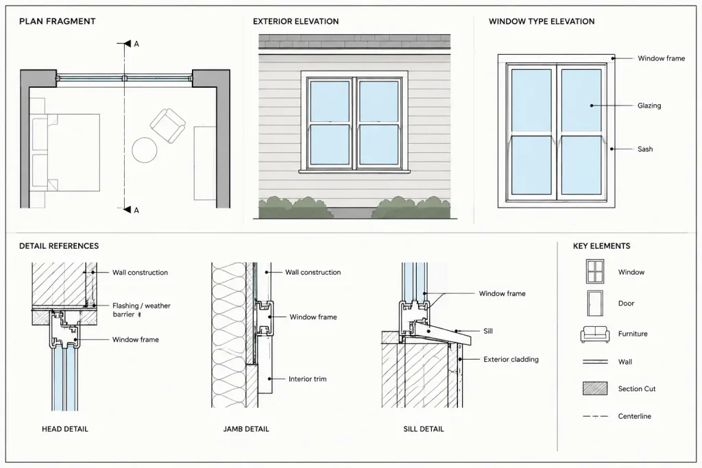
Detail coordination should also consider whether the drawings consistently communicate the opening basis. Plan dimensions, schedule dimensions, and detail dimensions must not silently refer to different parts of the assembly.
Manage revisions without losing traceability
Window changes often arrive through design development, product review, consultant coordination, owner decisions, or field verification. Update all connected locations as part of one revision task rather than treating the schedule as a separate cleanup item.
For each change, review the mark, plan opening, elevation graphics, type elevation, schedule row, detail references, and related notes. If a window is removed, determine whether its schedule row should be deleted, retained with an intentional status, or handled according to the project’s revision procedures.
A temporary coordination log can help identify unresolved decisions, but it should not become a competing source of final window data. Close or transfer each item before issue.
Perform a final schedule quality-control pass
Complete the review on both the working DWG and the plotted sheet. A schedule can be correct in model or paper space yet become difficult to use after plotting.
- Sort or organize rows according to the project’s stated method.
- Check for duplicate, missing, or obsolete marks.
- Confirm that headings explain ambiguous dimensional fields.
- Verify text fit, row alignment, lineweights, and page breaks.
- Compare schedule data with plans, elevations, type drawings, and details.
- Confirm that glazing and material terminology matches related project documents.
- Check that referenced details exist and show the correct conditions.
- Review revision indications according to the project’s document-control process.
The strongest window schedule is not necessarily the most detailed one. It is the schedule whose scope is clear, whose marks can be traced through the drawing set, and whose information has been checked against the actual architectural conditions. Product data, code criteria, fabrication requirements, and field dimensions still require project-specific verification by the responsible parties.
Use the schedule as a controlled coordination record
After the schedule is assembled, treat each row as part of a connected documentation chain. A mark should lead the reader from the opening shown in plan to its elevation or type graphic, scheduled information, and applicable construction details. If any part of that chain is unclear, the issue should be resolved rather than hidden in a general remark.
Review discrepancies by information source
When drawings disagree, first identify what each source is intended to communicate. A plan may control location, an elevation may show composition, a type drawing may explain operation, and a detail may describe the surrounding construction. The schedule should summarize and connect those decisions without silently overriding them.
Record unresolved conflicts through the project’s coordination process and assign responsibility for clarification. Avoid correcting only the schedule when the same change also affects tags, elevations, details, notes, or external project data.
Separate confirmed information from pending decisions
Do not present assumptions as finalized window data. If product selection, opening verification, glazing designation, or a detail reference remains unresolved, manage that status through the team’s established review method. Before an issue, confirm that temporary notes and placeholders have either been resolved or intentionally retained.
Check usability as well as data accuracy
A technically coordinated schedule can still fail if tags are difficult to find, headings are ambiguous, or references cannot be followed efficiently. Review the sheet from the perspective of someone who did not create it. The reader should be able to identify an opening, find its schedule entry, understand the basis of the listed information, and locate related drawings without guessing.
Window schedule coordination FAQ
Should a window schedule use type-based or instance-based marks?
The choice depends on the documentation strategy. Type-based marks work well when repeated windows are genuinely identical in the information being scheduled. Instance-based marks provide location-specific records when otherwise similar windows have different conditions. A project may also combine both methods if the distinction is clearly explained and consistently applied.
What does a scheduled window width or height represent?
It may represent a unit dimension, frame dimension, rough opening, masonry opening, or another defined reference. The heading or schedule notes should state the intended basis. Never assume that dimensions taken from different sources refer to the same part of the assembly.
Can CAD block attributes eliminate window schedule errors?
No. Attributes can reduce repeated data entry and help generate tables, but they do not confirm that a mark, value, wall condition, or design decision is correct. Extracted information still requires comparison with plans, elevations, type drawings, and details.
Does every wall condition require a different window type?
Not necessarily. The window configuration may remain the same while the surrounding head, jamb, sill, trim, flashing, or support condition changes. The documentation should distinguish window type information from installation-condition references.
How should deleted windows be handled in the schedule?
Follow the project’s revision and document-control procedure. Confirm that the opening, tag, schedule row, elevation graphics, references, and related notes are updated together. Avoid reassigning the former mark without a deliberate approach that preserves traceability.
What should be checked before issuing a window schedule?
Check for missing, duplicate, and obsolete marks; confirm the meaning of dimensional fields; compare operation and composition with elevations; verify wall-condition references; and review the plotted sheet for legibility. Product information and field conditions also require project-specific verification by the responsible parties.