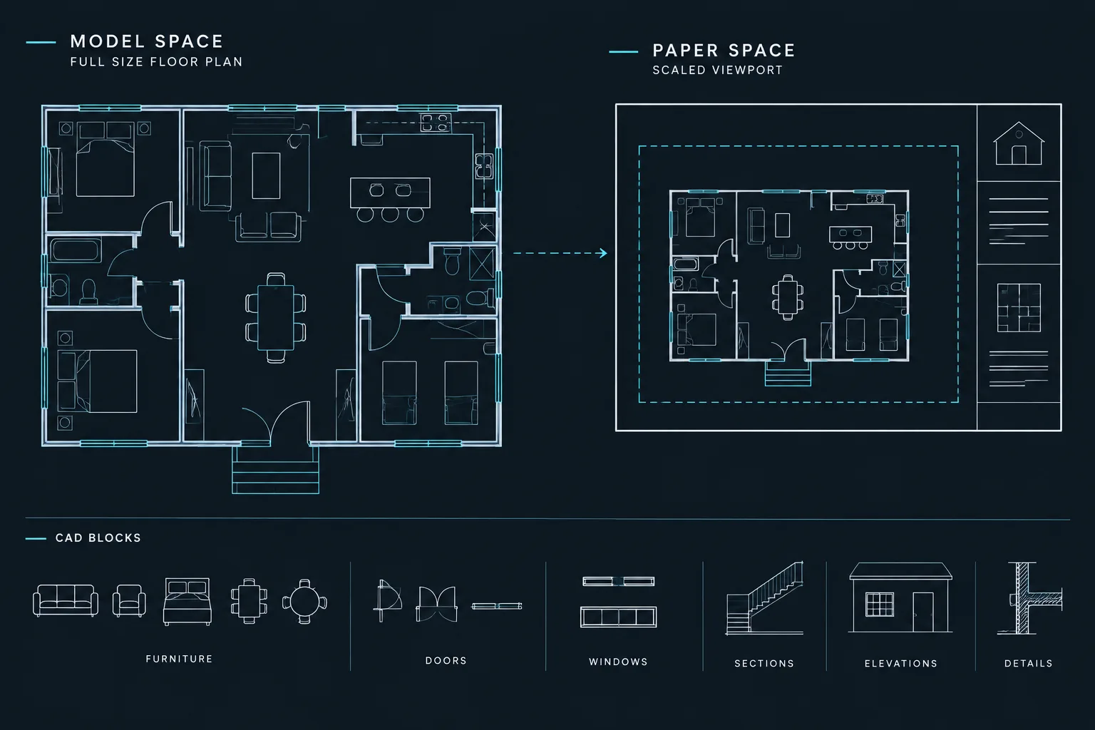
To draw full size in model space is to keep architectural geometry tied to the intended project size while managing its printed appearance separately. This distinction supports accurate measurement, dependable block insertion, coordinated references, and flexible sheet layouts.
This guide explains how model geometry, viewports, annotation, and plotting work together. It also provides a practical way to diagnose drawings that arrive at an unexpected size without relying on visual guesswork.
Architectural CAD geometry should normally represent the building at its actual intended size in model space. A wall, door, room, site boundary, or detail component is drawn according to the project’s working units rather than reduced to fit a sheet. The sheet scale is applied later through a paper space viewport or another controlled plotting method.
This separation between model size and presentation scale is fundamental to dependable DWG production. It allows dimensions to report meaningful values, blocks to remain reusable, external references to align, and multiple views of the same geometry to appear at different plotted scales without duplicating or resizing the design.
The principle is simple, but imported files, legacy drawings, mixed unit systems, and manually scaled details can make implementation less obvious. A reliable workflow begins by distinguishing actual geometry size from its printed appearance.
What “full size” means in architectural CAD
Drawing full size means that model-space geometry represents its real project size in the drawing’s declared unit system. It does not mean that the drawing must use a particular unit convention. An office may work in an imperial or metric environment, but every participant needs to understand what one drawing unit represents.
For example, the distance between two modeled wall faces should reflect the intended construction distance. The geometry should not be reduced merely because it will eventually appear in a viewport on a comparatively small sheet.
This approach creates two distinct environments:
- Model space: Contains building, site, detail, or diagram geometry at its intended size.
- Paper space: Contains the sheet layout, title block, viewports, and sheet-specific information.
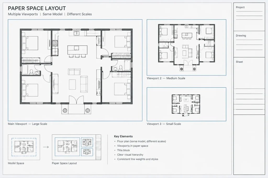
A viewport acts as a controlled window into model space. Its scale determines how large the full-size model appears on the sheet. Changing that viewport scale should alter the presentation, not the underlying building geometry.
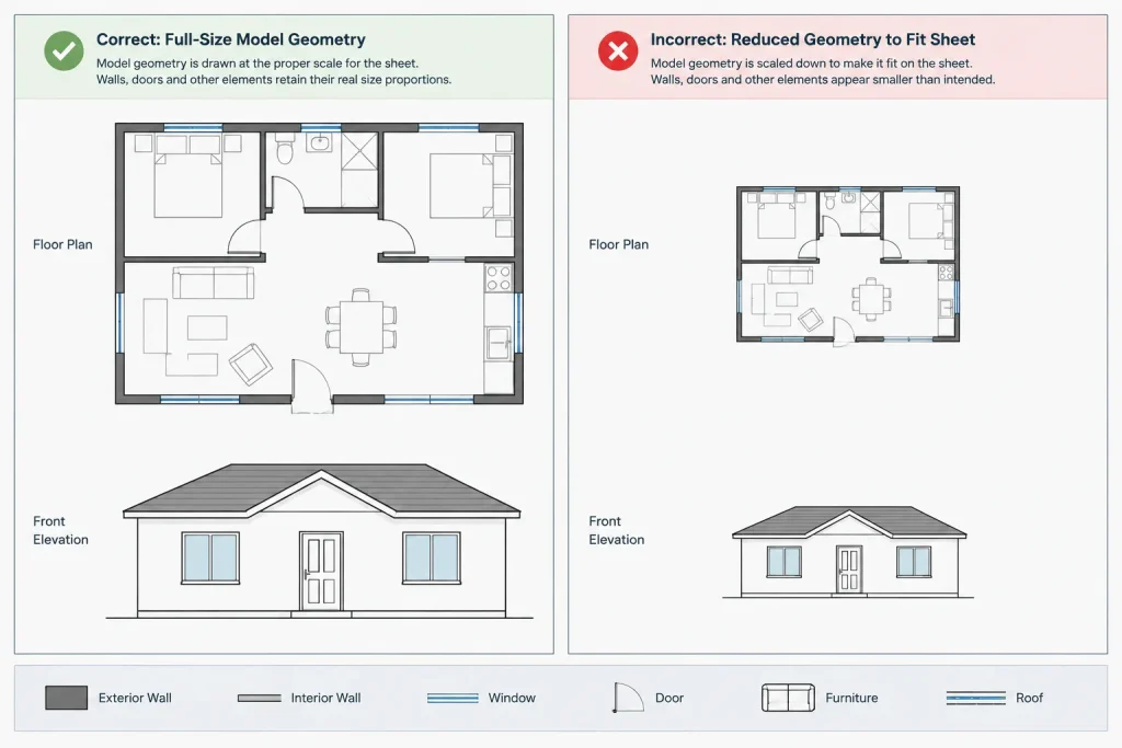
Why reduced model-space geometry causes problems
Scaling a floor plan down to make it fit a sheet may appear to solve an immediate plotting problem, but it transfers presentation decisions into the project geometry. This can create errors that spread through dimensions, references, schedules, blocks, and consultant coordination.
Dimensions can report misleading values
Associative dimensions measure the geometry they reference. If the plan has been reduced in model space, the measured distance no longer represents the intended building size unless a compensating dimension factor or other workaround is introduced. Such workarounds make the file harder to audit because the displayed value and measured geometry may disagree.
Blocks can arrive at inconsistent sizes
Architectural blocks are most useful when they are created in a known unit system and inserted without arbitrary correction. If the host plan has been reduced, users may scale doors, furniture, fixtures, symbols, and equipment differently just to make them look appropriate. The drawing can then contain visually similar objects with unrelated scale factors.
External references may not align
Floor plans and consultant backgrounds generally need a common origin, orientation, and unit interpretation. Scaling a referenced plan to fit a sheet breaks that coordinated relationship. A file may look correct in one viewport while no longer matching the project coordinate framework.
One model cannot serve several presentation scales cleanly
A single plan may appear as an overall view, an enlarged area, and a coordination background. If the geometry itself is tied to one plotting scale, additional views often require copied and resized geometry. Full-size model geometry allows each viewport to present the same source at an appropriate scale.
Model size, viewport scale, and annotation are different controls
| Control | Primary purpose | What it should affect |
|---|---|---|
| Model geometry | Represent the project | Actual locations, lengths, openings, objects, and assemblies |
| Viewport scale | Fit a view onto a sheet | The apparent size of model geometry in paper space |
| Annotation setup | Maintain readable notes and symbols | Text, dimensions, tags, leaders, and other plotted information |
| Plot configuration | Produce the final sheet | Paper size, plot area, orientation, plot styles, and output settings |
These controls are related, but they are not interchangeable. If a plan is too large for a sheet, adjust the viewport or sheet arrangement rather than shrinking the building. If text is unreadable, correct the annotation workflow rather than resizing nearby walls. If an imported block is incorrect, investigate its source units and definition rather than assuming the entire model needs adjustment.
A practical full-size drawing workflow
1. Confirm the project unit convention
Before drafting, identify what one drawing unit represents and confirm that the team uses the same interpretation. Check template settings, dimension styles, existing project files, and known geometry. Do not rely only on how large the drawing appears on screen because zoom level has no relationship to actual model size.
2. Test a known distance
Measure a trustworthy element from the project information, such as a documented grid spacing or overall building dimension. Compare the measured CAD distance with the stated project value. Choose an element that has been verified rather than estimating from furniture or graphic symbols.
3. Draft geometry at intended size
Create walls, openings, stairs, casework, site elements, and other components using project dimensions. Avoid applying a global reduction factor for plotting. Details can also be drafted full size in model space, even when they will be shown through a much more enlarged viewport than a floor plan.
4. Place the sheet framework in paper space
Set up the title block and sheet composition in a layout. Create viewports for plans, elevations, sections, or details. Select a suitable viewport scale based on the required content, legibility, and office standards.
5. Lock coordinated viewports
After a viewport has the intended view and scale, lock it to reduce accidental zooming or scale changes. A locked viewport does not replace review, but it helps preserve an established sheet composition while users pan and zoom elsewhere in the file.
6. Verify annotation behavior
Annotation may be placed in model space, paper space, or a controlled combination of both. Whichever method the project uses, test the plotted result. Confirm that text, dimensions, tags, callouts, and linework remain legible and that annotation does not unexpectedly change when a viewport scale is adjusted.
Handling files that arrive at the wrong apparent size
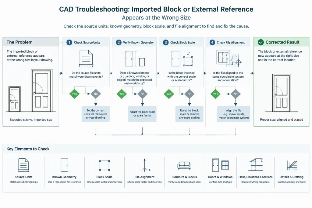
When an imported DWG, block, or external reference appears too large or too small, do not immediately scale it by eye. First identify the reason.
- Measure a known object in both the source and host files.
- Confirm what one drawing unit represents in each file.
- Check whether insertion-unit interpretation is contributing to the result.
- Determine whether the source geometry was already reduced for plotting.
- Look for nonuniform object scale factors or nested blocks.
- Preserve an untouched copy of the received file before making corrections.
A correction should be based on a verified conversion or source error, not visual fit. If a consultant file must remain unchanged, document the coordination decision and use a controlled reference workflow. Arbitrarily resizing each new issue can make revision replacement unreliable.
Common exceptions and misleading situations
Not-to-scale diagrams
Some diagrams communicate relationships rather than measurable construction geometry. They may be intentionally schematic. Label and manage them so users do not mistake them for scaled plans or details.
Legacy details drawn for a sheet
Older CAD files sometimes contain details composed directly at plotted size. Reusing them requires careful evaluation. Measure known content, review text and dimension overrides, and decide whether the detail should be rebuilt as full-size geometry rather than mixed into a current model-space workflow.
Graphic symbols
North arrows, section marks, elevation references, and similar symbols are often managed for consistent printed appearance rather than as physical building objects. Their size may be controlled through paper space, annotative behavior, or scale-specific blocks. This does not justify scaling the architectural model.
Presentation-only illustrations
A decorative diagram or rendered entourage element may not carry measurable project information. Even so, keep it separate from coordinated construction geometry and use clear layers or file organization to prevent accidental measurement.
Quality-control checks before plotting
- Measure several verified project distances in model space.
- Inspect block scale factors for unexpected values.
- Confirm that externally referenced files align without arbitrary resizing.
- Check viewport scales and lock viewports after composition is approved.
- Review dimensions for overrides or scale compensation.
- Plot or preview the sheet to assess annotation and lineweight legibility.
- Confirm that enlarged views reference the same coordinated geometry where practical.
- Record any intentional schematic or not-to-scale content clearly.
A better rule for everyday CAD work
Use model space to describe the project and paper space to describe the sheet. When those roles remain separate, a floor plan can support dimensions, blocks, external references, enlarged views, and multiple sheets without being resized for each presentation need.
If geometry appears at the wrong size, investigate units and source conditions. If it does not fit on the sheet, adjust the view. If annotation is unreadable, correct the annotation setup. Keeping those decisions separate produces DWG files that are easier to measure, coordinate, revise, and reuse.
How to diagnose a model-space scale problem
When a drawing looks incorrect, first identify whether the problem belongs to the geometry, the file’s unit interpretation, the viewport, or the annotation. Objects can appear too large or too small for several reasons, and scaling the entire model is rarely a safe first response.
- If measured geometry is wrong: Compare it with verified project information and investigate the source file, drawing units, insertion behavior, and prior scaling.
- If geometry measures correctly but does not fit the sheet: Review the viewport scale, crop, orientation, and sheet composition.
- If blocks do not match the host drawing: Check the block definition, source-unit convention, insertion settings, and object scale factors.
- If references do not align: Confirm the shared origin, orientation, units, and whether either file has been resized.
- If notes or symbols plot inconsistently: Review the annotation method instead of changing the architectural geometry.
Documenting the workflow for project teams
A full-size workflow depends on shared expectations. Record the drawing-unit convention, reference origin, annotation approach, and sheet setup in the project’s CAD instructions or handoff notes. Team members should also know which files are authoritative and which diagrams are intentionally schematic.
Before issuing or sharing a DWG, remove unexplained scale corrections where practical and document any exceptions that must remain. This makes later revisions easier to compare and reduces the chance that another user will apply an additional correction to geometry that was already altered.
Frequently asked questions
Should architectural plans be drawn full size in model space?
Normally, yes. The geometry should represent the intended project size according to the drawing’s established unit convention. Its appearance on a sheet is then controlled through a viewport or another documented plotting workflow.
Does full size mean every drawing must use the same unit system?
No. Full size describes the relationship between the geometry and the selected drawing units. The essential requirement is that users understand what a drawing unit represents and coordinate that interpretation across related files.
Why does a full-size plan look too large for the layout?
Model space is not limited by the sheet boundary. If correctly sized geometry does not fit the layout, adjust the viewport scale, view extents, orientation, or sheet composition rather than shrinking the building model.
Should an imported DWG be scaled when it appears at the wrong size?
Not until the cause is verified. Measure a known element and compare the source and host unit conventions. Also inspect insertion behavior, nested blocks, object scale factors, and evidence that the source was previously reduced for plotting.
Can details also be drawn full size?
Yes. Detail geometry can represent the intended assembly size in model space while an enlarged viewport controls how it appears on the sheet. Legacy details prepared directly for printed presentation should be evaluated before reuse.
Does drawing full size solve annotation scaling automatically?
No. Text, dimensions, tags, leaders, and symbols still require a consistent annotation strategy. Their plotted appearance should be checked at the viewports and sheet conditions used for the project.
What is the safest way to correct reduced legacy geometry?
Keep an untouched copy, identify a verified distance, inspect dimension overrides and block scaling, and determine whether the content should be converted or rebuilt. Avoid correcting it solely by matching its visual appearance to another drawing.