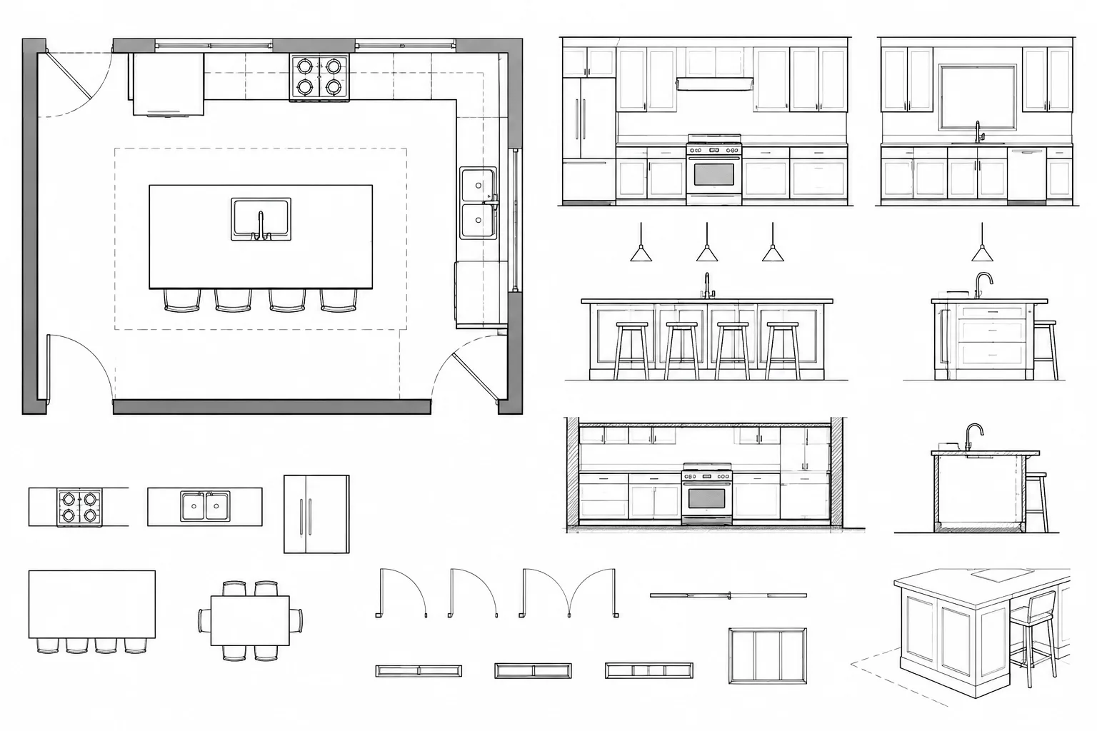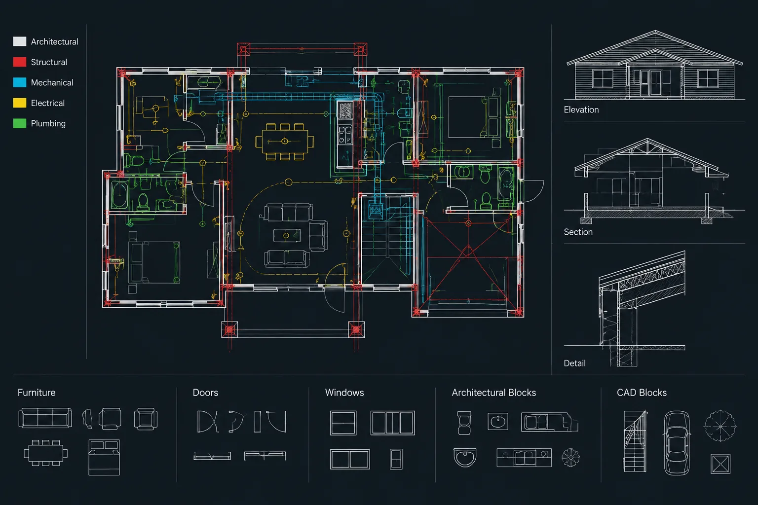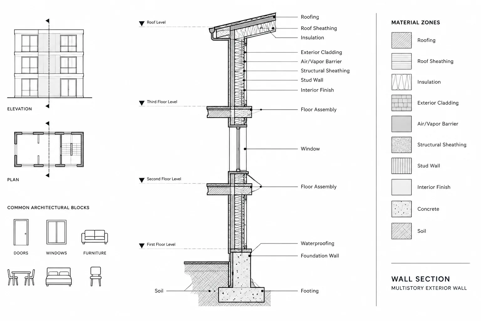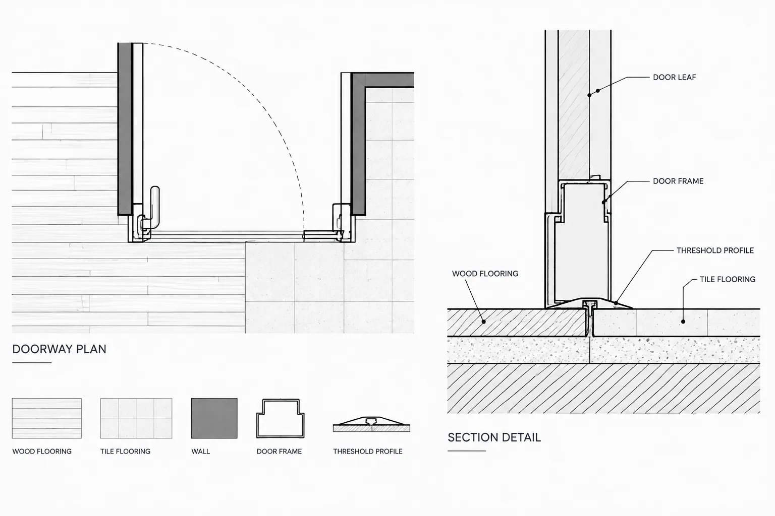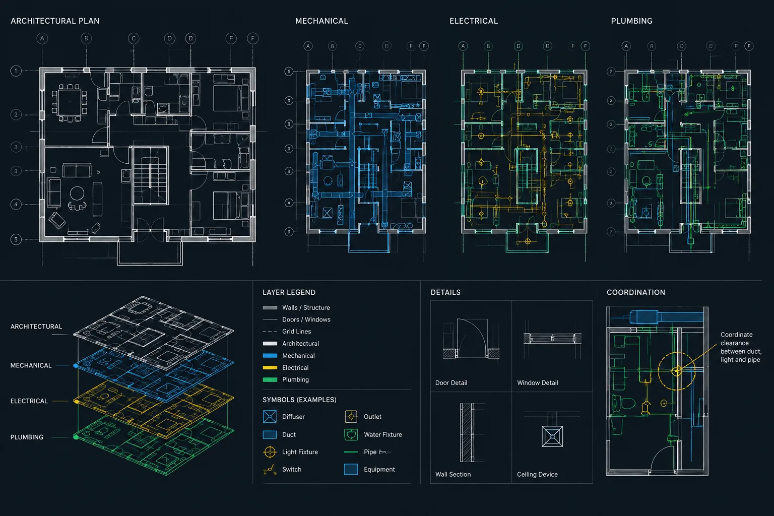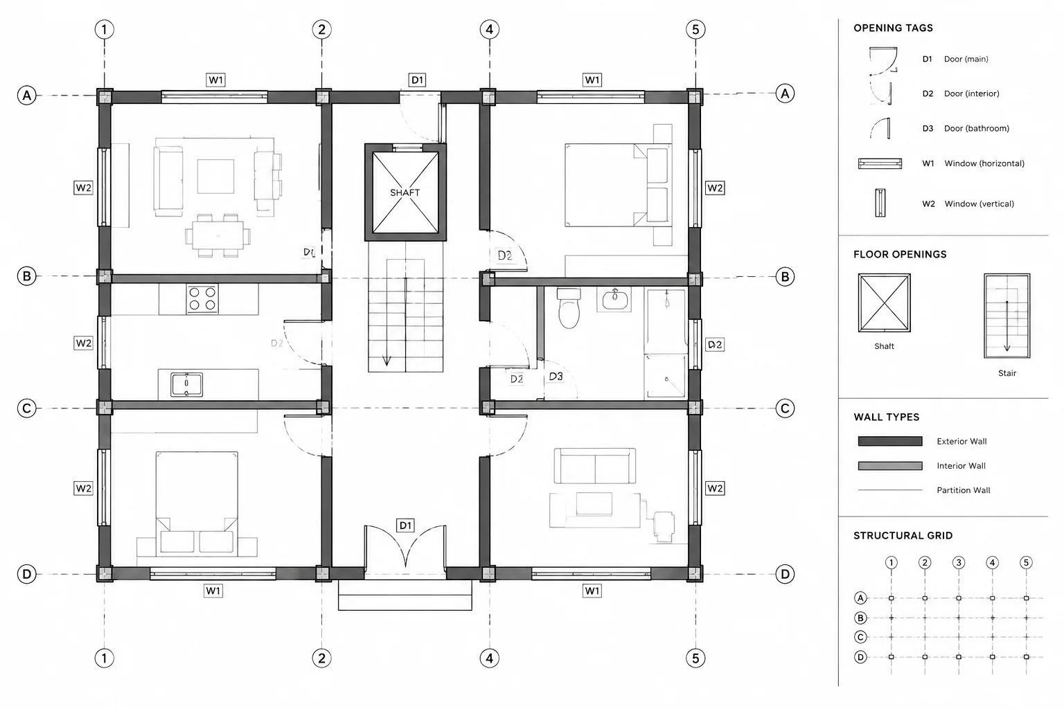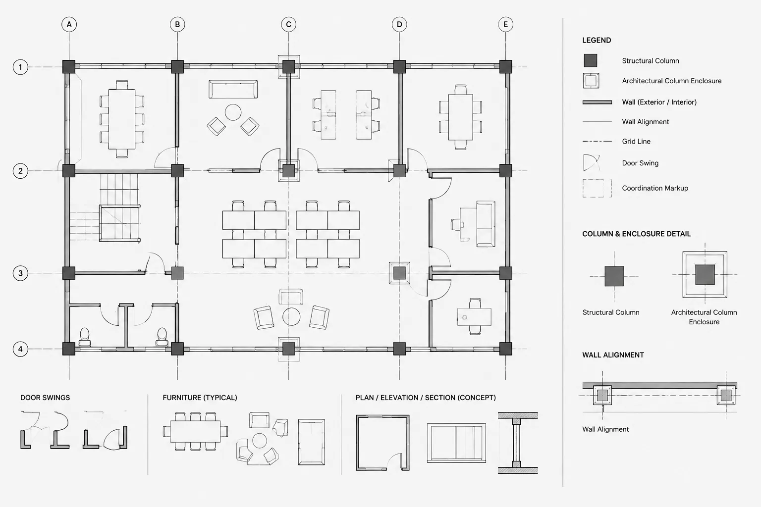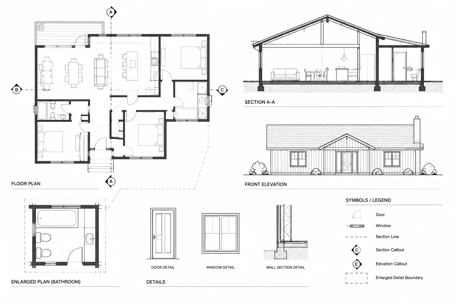
Ceiling height coordination in CAD requires more than drawing boundaries on a reflected ceiling plan. Every transition must remain consistent with the floor plan, sections, interior elevations, finish information, ceiling-mounted components, and relevant consultant backgrounds.
This workflow explains how to document soffits and bulkheads as coordinated architectural elements. It focuses on reference geometry, height datums, drawing hierarchy, cross-view checking, and the treatment of unresolved conditions so that the drawing set communicates one clear design intent.
Ceiling changes are easy to underestimate because they often appear as simple lines on a reflected ceiling plan. In a coordinated architectural drawing set, however, each ceiling edge may relate to a wall, beam, duct, cabinet, curtain pocket, lighting layout, or finish transition. If those relationships are not resolved, the floor plan, reflected ceiling plan, interior elevations, and sections can describe different conditions.
A reliable ceiling height coordination in CAD workflow treats soffits and bulkheads as three-dimensional architectural elements rather than isolated graphics. Their horizontal boundaries, vertical faces, underside elevations, finishes, and relationships to nearby construction should remain consistent in every affected view.
Clarify the terminology before drafting
The words soffit and bulkhead are sometimes used interchangeably, and regional office conventions vary. A soffit generally describes the exposed underside of an overhead construction element. A bulkhead often describes a dropped enclosure used to conceal services, frame an opening, or create a ceiling transition. One constructed feature may have both a vertical bulkhead face and a horizontal soffit surface.
The project team should establish how these terms will be used in notes, tags, details, and finish information. Consistent terminology is more important than forcing every condition into a universal definition.
Identify why the ceiling changes
Before drawing a dropped area, determine what creates it. Common causes include:
- Structural beams or changes in floor construction above
- Mechanical ducts, piping, or other building services
- Cabinetry, shelving, or full-height architectural millwork
- Lighting coves, curtain pockets, tracks, or recessed equipment
- Changes between ceiling materials or suspension systems
- Acoustic, visual, or spatial design goals
- Transitions at corridors, entries, and changes in room use
This distinction affects coordination. A decorative ceiling feature may be adjustable during design, while a bulkhead concealing a major service route may depend on consultant information. Avoid presenting an unresolved enclosure as final merely because its outline looks complete in CAD.
Build the ceiling from coordinated reference geometry
Start with the current floor plan and consultant backgrounds rather than tracing an earlier reflected ceiling plan. Confirm wall faces, door openings, columns, casework, room boundaries, grids, and relevant overhead systems. If the project uses external references, maintain stable origins and avoid moving backgrounds to make local drafting easier.
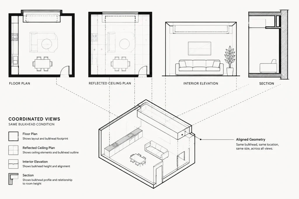
Construct ceiling boundaries from meaningful architectural references. For example, align an edge with a finished wall face, centerline, cabinet face, structural element, or other documented control. A line positioned only by eye may become difficult to update when the plan changes.
Where a ceiling boundary follows an irregular room shape, use clean, continuous geometry where practical. Remove overlapping segments, tiny gaps, and duplicate lines. Clean boundaries improve hatching, area checking, selection, and later revisions.
Separate visible boundaries from coordination information
Not every line used to develop a ceiling should plot with the same emphasis. A practical layer structure may distinguish:
- Primary ceiling and soffit edges
- Overhead or hidden references
- Ceiling grids and finish patterns
- Lighting and ceiling-mounted equipment
- Ceiling height tags and notes
- Consultant backgrounds
- Non-plotting construction or coordination geometry
Use the project layer standard rather than creating near-duplicate layer names for one local condition. Color, linetype, and plotted weight should support the office drawing hierarchy. Boundaries that define a visible change usually need more emphasis than grid patterns or background information.
Represent the condition in each drawing view
A ceiling feature rarely belongs to only one sheet. Decide what each view needs to communicate without repeating unnecessary information.
| Drawing view | Primary purpose | Typical ceiling information |
|---|---|---|
| Floor plan | Show usable space and elements viewed at the plan cut | Relevant overhead lines, enclosure relationships, and references to sections or details |
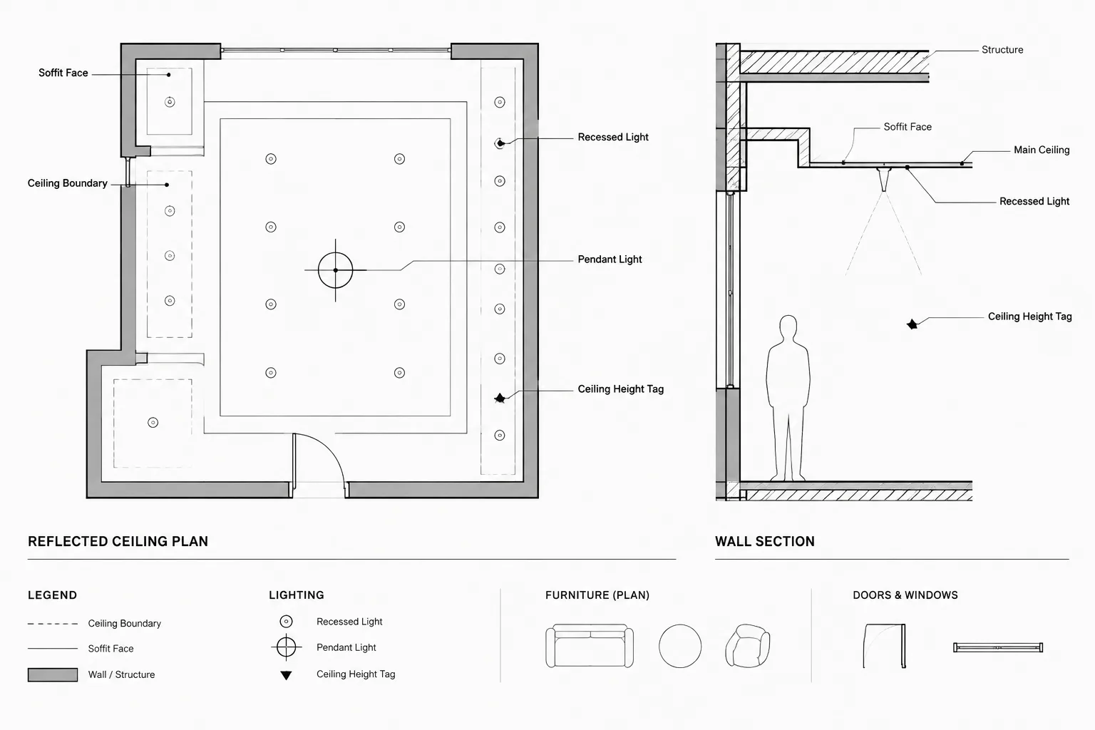
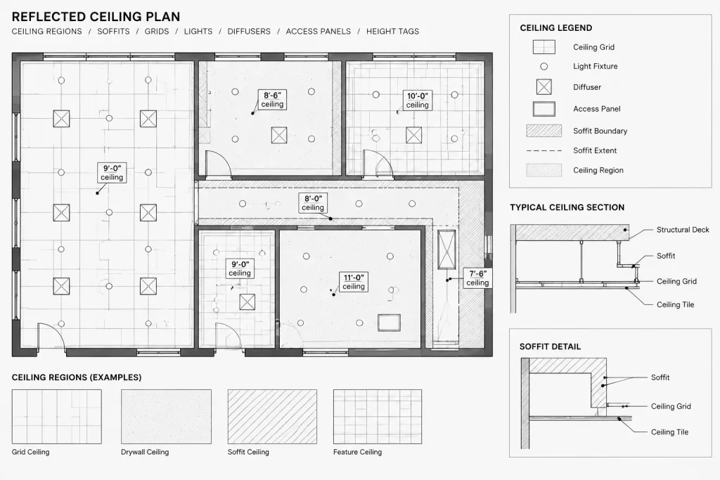
| Reflected ceiling plan | Describe the ceiling as viewed from below | Ceiling boundaries, grids, heights, materials, lights, diffusers, access panels, and other mounted items |
| Building or wall section | Explain vertical construction | Underside elevation, depth, support relationship, and concealed space |
| Interior elevation | Show the visible face within a room | Bulkhead profile, alignment with openings or millwork, finishes, and visible devices |
| Detail | Resolve a specific assembly or junction | Edges, reveals, trim, interfaces, and attachment intent appropriate to the project stage |
| Finish or ceiling schedule | Organize repeated properties | Ceiling type, finish designation, and related notes where the project uses scheduled information |
The views should complement one another. A reflected ceiling plan may establish the horizontal extent and underside elevation, while a section explains depth and construction. Avoid crowding every assembly note into the plan if a referenced detail communicates it more clearly.
Use a consistent height reference
Ceiling tags are useful only when their datum is understood. Establish whether heights are referenced to the project level, finished floor, or another defined datum. Use the same basis across the reflected ceiling plan, sections, interior elevations, and schedules.
Place tags within clearly bounded ceiling regions whenever possible. If a leader is necessary, point it to the intended surface rather than to a nearby boundary. Where adjacent ceiling areas differ, confirm that each tag is visually associated with the correct region.
Do not infer a final height solely from a consultant background or a rough design sketch. A coordinated underside elevation may depend on structure, service clearances, suspension depth, finishes, and access requirements. Record unresolved heights as coordination items instead of silently assigning values.
Coordinate the vertical face and underside separately
A common drafting error is to show the underside of a soffit but omit its vertical return. Another is to draw a bulkhead face in elevation without defining how far it projects in plan. Check both components:
- The horizontal footprint or underside area
- The vertical face and its top and bottom limits
- The relationship to adjacent walls, ceilings, and openings
- The finish on each exposed surface
- The termination at corners, columns, glazing, or cabinetry
In sections and elevations, project geometry from the coordinated plan rather than redrawing the feature independently. This reduces drift between views and makes changes easier to track.
Check ceiling-mounted components at transitions
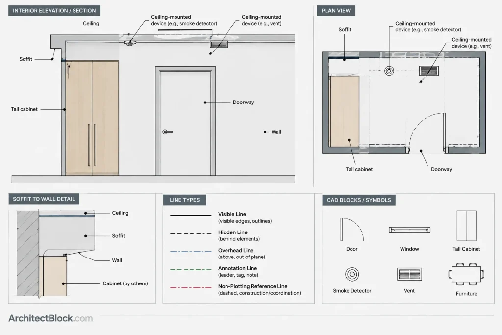
Ceiling edges often compete with lights, diffusers, sprinklers, speakers, detectors, access panels, tracks, and signage. The architectural drawing should provide a legible organizing framework while recognizing that consultant drawings may govern parts of the technical layout.
Review components near every height change. Look for fixtures divided by an edge, devices placed on sloped or vertical faces unintentionally, access panels blocked by partitions or millwork, and crowded clusters around narrow soffits. Also compare ceiling layouts with door swings, tall cabinets, operable partitions, and other elements that may affect access or clearance.
Life-safety devices, fire protection layouts, and required access provisions must be verified by the responsible project professionals. A visually balanced CAD layout is not evidence of technical or code compliance.
Control repeated soffits without hiding variation
Blocks can be useful for genuinely repeated ceiling features, such as modular recesses or standard curtain pockets. Use them only when the geometry and annotation are intended to remain consistent. A block that contains a fixed height note can become misleading if instances occur at different elevations.
For repeated but variable conditions, keep project-specific values outside the block or use a managed attribute workflow. Assign logical insertion points and document what the block represents. Do not group unrelated lights, ceiling outlines, and room-specific notes into one oversized block merely to speed selection.
Run a focused coordination review
A useful review is more than checking whether lines align on one sheet. Trace each significant ceiling transition through the drawing set and ask:
- Does the reflected ceiling plan show a complete, unambiguous boundary?
- Is the underside height identified using the project datum?
- Does the floor plan show the condition where it affects plan reading?
- Do sections and interior elevations show the same horizontal limits?
- Is the vertical face accounted for?
- Are ceiling-mounted components coordinated with the transition?
- Does the feature conflict with structure, services, openings, or millwork?
- Are finish changes and termination points explained?
- Are unresolved conditions visibly tracked for coordination?
Overlaying or comparing relevant views can reveal shifted edges and mismatched extents. Even without automated comparison tools, temporary projection lines and non-plotting check geometry provide a dependable way to verify alignment.
Avoid common drafting failures
- Floating ceiling lines: Boundaries lack a clear relationship to walls, grids, or other controls.
- Tags without defined regions: It is unclear which ceiling surface a height applies to.
- Plan-only solutions: A dropped element is drawn in the reflected ceiling plan but has no coordinated section profile.
- Copied consultant graphics: Service information is duplicated into the architectural file and later becomes outdated.
- Uniform lineweight: Ceiling edges, grids, fixtures, and backgrounds compete visually.
- Premature certainty: An unverified depth or height is presented as resolved construction information.
- Incomplete terminations: The bulkhead works in the middle of a room but is unresolved where it meets glazing, columns, or cabinetry.
Make ceiling coordination part of the drawing workflow
Ceilings should be reviewed whenever walls, structure, mechanical distribution, lighting, or millwork changes. Waiting until the reflected ceiling plan is nearly complete tends to convert design coordination into graphic patching.
A strong CAD workflow maintains one coordinated architectural idea across all views: where the ceiling changes, what establishes the change, how high each surface is, what the transition looks like vertically, and which systems occupy the surrounding space. When those questions are answered consistently, soffits and bulkheads become clear architectural elements rather than unexplained lines above the plan.
Use the workflow as a drawing-set review
The most effective way to apply this process is to follow each ceiling transition through every view in which it appears. Begin with the architectural controls that establish its location, confirm the underside and vertical face, and then compare that geometry with sections, elevations, finishes, millwork, structure, and building services.
Keep design intent separate from information that still requires consultant or project-team verification. Non-plotting geometry, coordination notes, and clearly managed backgrounds can help the team investigate conflicts without making unresolved conditions appear final.
Practical review sequence
- Locate the transition: Identify the wall face, grid, opening, casework, structure, or other reference that controls the boundary.
- Define the region: Make the ceiling area clear enough that its height and finish cannot be confused with an adjacent surface.
- Resolve the profile: Check the underside, vertical return, projection, depth, and termination in the appropriate sections or elevations.
- Compare disciplines: Review nearby structure, ducts, piping, lighting, diffusers, access panels, and other coordinated systems.
- Check presentation: Confirm that layers, lineweights, linetypes, tags, and references support a readable drawing hierarchy.
- Track uncertainty: Flag missing elevations, incomplete consultant information, and unresolved junctions rather than assigning unsupported values.
Before issuing the drawings, inspect the ceiling transition at corners, openings, columns, glazing, and cabinetry. These termination points commonly reveal inconsistencies that are not obvious along a straight run.
Frequently asked questions
What is the difference between a soffit and a bulkhead?
A soffit generally refers to the exposed underside of overhead construction. A bulkhead commonly refers to a dropped enclosure that conceals services, frames an opening, or forms a ceiling transition. A single feature may include both a horizontal soffit surface and a vertical bulkhead face, so project terminology should remain consistent.
Which drawing should control a ceiling height?
The project team should use a clearly defined datum consistently across the reflected ceiling plan, sections, interior elevations, and schedules. No view should be updated in isolation when a height changes.
Should soffits appear on the floor plan?
They should appear where the overhead condition affects plan reading, spatial coordination, or references to sections and details. The reflected ceiling plan remains the primary view for ceiling boundaries, heights, finishes, and mounted components.
How should an unresolved ceiling height be documented?
Record it as a coordination item and identify the information needed to resolve it. Do not infer a final value from an incomplete background or make an unverified height appear to be approved construction information.
Can repeated soffits be created as CAD blocks?
Yes, when the geometry is genuinely repeated and the block does not conceal project-specific variation. Variable heights, finishes, and room-specific notes should be managed separately or through a controlled attribute workflow.
Why do ceiling boundaries become inconsistent between views?
Common causes include independent redrawing, outdated consultant backgrounds, unclear reference geometry, copied linework, and changes made in only one view. Projection geometry and view comparisons help identify this drift.
What should be checked near a ceiling transition?
Review the boundary against walls, openings, millwork, structure, services, lighting, diffusers, access panels, and other ceiling-mounted elements. Required clearances, life-safety provisions, and technical layouts must be verified by the responsible project professionals.