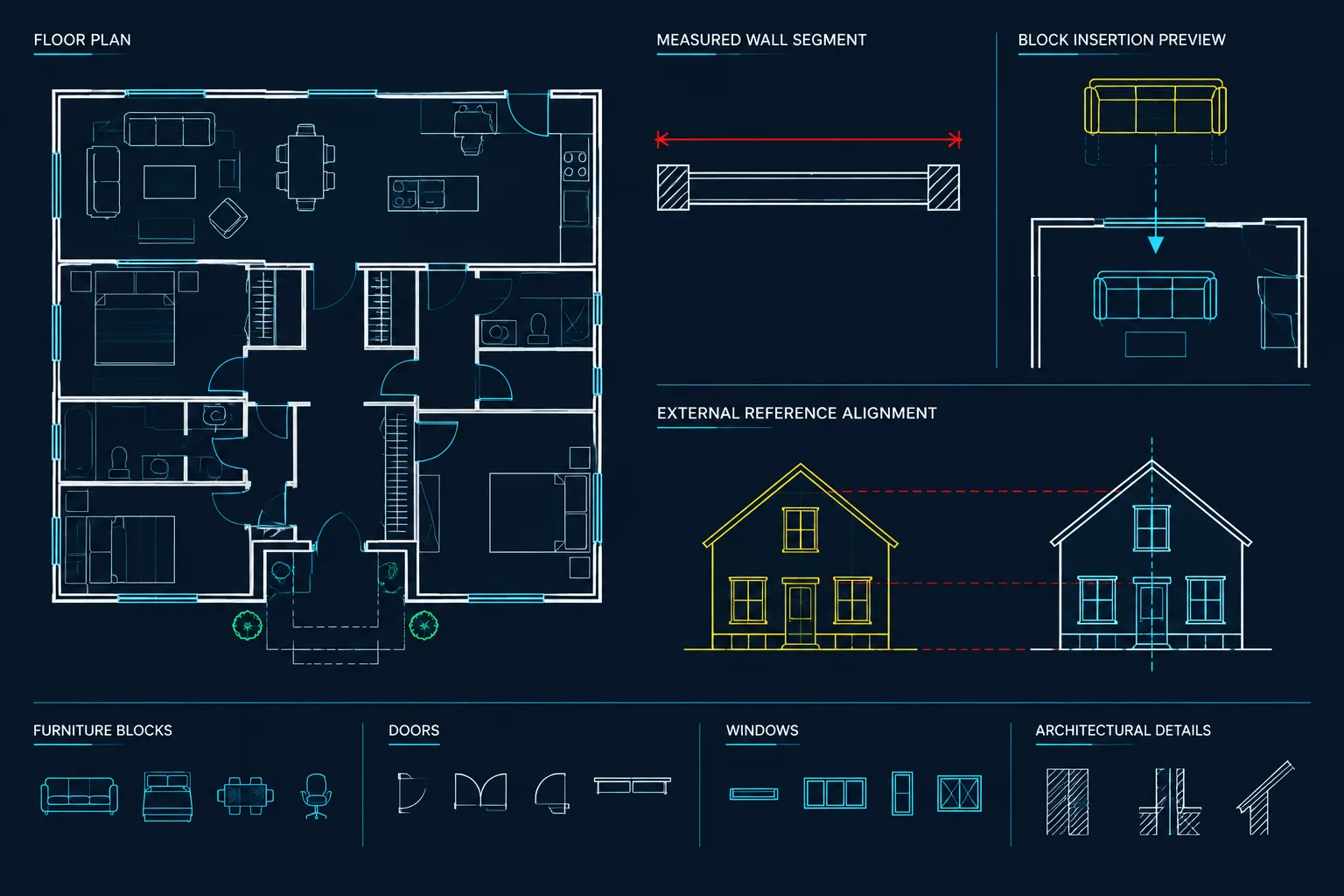
AutoCAD drawing units for architecture affect far more than the way a distance is displayed. They influence how blocks enter a file, how external references coordinate, how imported backgrounds are interpreted, and whether model geometry remains dependable across the project team.
This guide explains how to distinguish model-space units from insertion settings and plotted scale, verify an unfamiliar DWG against known project geometry, and correct mismatches without concealing their cause. Use it when preparing a template, reviewing consultant files, troubleshooting misplaced content, or documenting a coordinated CAD workflow.
Incorrect drawing units can quietly disrupt an architectural CAD file. A floor plan may look normal until a door block arrives at the wrong size, an external reference is inserted far too large, or a measured distance fails to match the project documents. These problems often result from confusion between drawing geometry, unit settings, insertion scaling, and plotted scale.
A reliable workflow begins with one principle: draw architectural geometry at full size in model space using one consistent real-world unit. The project team must then document that unit, verify incoming files, and avoid using scale commands as an unexamined repair tool.
What AutoCAD Drawing Units Actually Control
In a standard DWG workflow, a line has a numerical length but does not inherently know that the value represents inches, feet, millimeters, or another real-world unit. The project convention gives that number meaning.
Unit-related settings help AutoCAD display values and determine how drawings, blocks, and references with declared insertion units interact. These settings do not automatically prove that existing geometry was drawn correctly. A file can be labeled as one unit while its objects were created according to another convention.
It is useful to separate four concepts:
- Model-space drawing unit: The real-world unit represented by one drawing unit.
- Display format: How distances and coordinates appear to the user.
- Insertion units: Information used when content from one file is inserted into another.
- Plot scale: The relationship between full-size model geometry and its printed or PDF representation.
Changing a display format does not necessarily resize objects. Likewise, changing an insertion-unit setting does not automatically correct geometry that was drafted at the wrong scale.
Choose One Model-Space Convention
Before drafting begins, the project team should decide what one drawing unit represents. Architectural offices working in the United States may use an inch-based convention, while civil, survey, landscape, or engineering files may use feet or metric units. The correct choice depends on the project and the team’s established workflow.
The important requirement is consistency. Walls, doors, grids, details, annotations, blocks, and xrefs should follow a documented convention appropriate to their file type. Do not assume that every consultant uses the same unit merely because the project is located in the same region.
| Item to document | Why it matters |
|---|---|
| Model-space unit convention | Defines what each numerical drawing unit represents. |
| Coordinate basis | Helps referenced files align without manual repositioning. |
| Insertion-unit setting | Influences automatic scaling when compatible files are inserted. |
| Block library convention | Prevents doors, fixtures, furniture, and symbols from arriving at unexpected sizes. |
| Consultant file conventions | Identifies files that may require a controlled unit conversion. |
| Sheet and viewport method | Keeps model units separate from plotted drawing scale. |
Verify Units with Known Geometry
Never determine a file’s units from appearance alone. A floor plan can look proportionally correct at almost any zoom level. Instead, measure an element whose real-world size can be confirmed from reliable project information.
Useful verification references may include a clearly dimensioned grid spacing, an overall building dimension, a surveyed property segment, or another controlled project measurement. Avoid relying on furniture, vehicles, trees, or generic symbols because block geometry may be schematic or incorrectly scaled.
A practical verification sequence
- Open the file without scaling its contents.
- Review its unit and insertion settings.
- Measure a known segment using an inquiry or measurement tool.
- Compare the measured value with a verified project dimension.
- Check a second known segment elsewhere in the drawing.
- Record the conclusion before attaching, inserting, or converting the file.
Checking more than one segment helps distinguish a unit mismatch from distorted geometry, an inaccurate source, or an isolated drafting error.
Drawing Units Are Not Viewport Scales
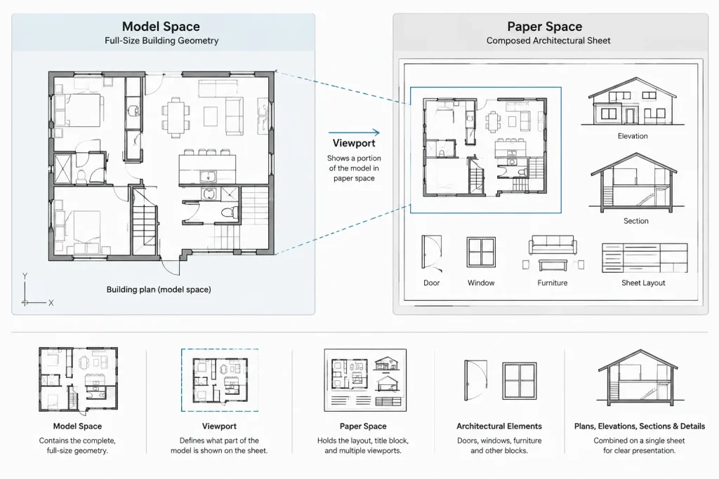
Model-space units and sheet scales solve different problems. Architectural objects should generally be drawn at their real size in model space. A paper-space viewport then presents that geometry at the required sheet scale.
Do not shrink a building plan in model space simply to make it fit on a sheet. That approach can disrupt dimensions, block insertion, xref alignment, area calculations, hatch behavior, and coordination with consultant files. Adjust the viewport and sheet composition instead.
Annotation also needs a deliberate strategy. Text, dimensions, symbols, and leaders may be managed with annotative behavior, scale-dependent styles, paper-space annotation, or a documented hybrid method. Regardless of the method, changing the size of the underlying building geometry is not a substitute for annotation setup.
How Unit Mismatches Affect Blocks
Blocks are a common point of failure because three factors may interact: the size of the source geometry, the source file’s declared insertion units, and the target drawing’s insertion units.
Before adding a downloaded or consultant-provided block to a project library, inspect it in a temporary file. Measure recognizable geometry, review text orientation, examine nested blocks, and confirm that the content is intended to represent a real object rather than a diagrammatic symbol.
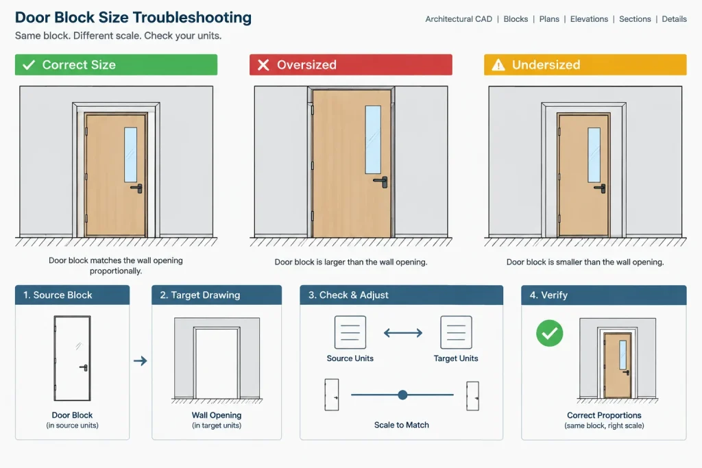
If a block arrives at an incorrect size, do not repeatedly adjust its insertion scale and move on. Determine whether:
- The block geometry was created using a different unit convention.
- The block definition has incorrect or undefined insertion-unit information.
- The host drawing has an inappropriate insertion-unit setting.
- A nested block introduces an additional scale.
- The object is intentionally diagrammatic and should not be treated as full-size geometry.
Once corrected, save a verified master block rather than expecting users to remember a special scale factor every time it is inserted.
Coordinate Xrefs Without Guesswork
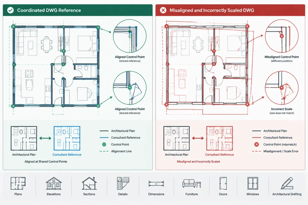
An xref must be checked for both units and coordinates. Correct units do not guarantee correct alignment, and correct visual alignment does not prove that the units are consistent.
When receiving a consultant background, preserve the original file and test a copy. Confirm the source convention with the consultant when possible. Measure known geometry, inspect the insertion result, and compare shared control points. If conversion is necessary, document who performed it, what was changed, and which file is now authoritative.
Avoid dragging, rotating, and scaling an xref by eye until it appears to fit. That can hide a serious coordination problem. An architectural background and a consultant file should align through an agreed coordinate and unit workflow, not through visual approximation.
Imported PDFs and Raster Images Need Separate Treatment
PDF underlays and raster images may not provide trustworthy real-world units. A PDF could have been printed from an unknown sheet size, reduced during scanning, cropped, or generated with a different page setup. A raster image may also contain perspective or scanning distortion.
Calibrate this material only against a verified dimension or control distance. After scaling, check another known distance in a different direction. If the second check does not agree, the source may be distorted and should not be treated as precise base geometry.
Keep traced or interpreted content distinguishable from verified survey or design information. Scaling an image to one known distance does not make every part of the image accurate.
Safe Ways to Correct a Unit Error
Before correcting a unit mismatch, save an untouched copy and determine the intended result. A controlled correction may involve changing file metadata, scaling geometry, redefining a block, or creating a converted coordination file. These actions are not interchangeable.
After any conversion:
- Measure at least two known distances.
- Confirm that xrefs still align at agreed control points.
- Inspect dimensions, leaders, text, hatches, and linetypes.
- Check block scales and nested content.
- Review layouts and viewport scales.
- Regenerate a test PDF and inspect graphic output.
- Record the conversion in the project notes or file history.
Be especially careful when a file contains both model geometry and annotation. Scaling every object indiscriminately can create new problems even when the building outline becomes the expected size.
Common Warning Signs
- A familiar door, fixture, or furniture block appears dramatically too large or too small.
- An xref is visible but extends far beyond the host drawing.
- Measured values do not resemble the labeled dimensions.
- A file aligns only after applying an unexplained scale factor.
- Hatches or linetypes look unusually dense or sparse after insertion.
- Coordinates differ greatly between files that are expected to share an origin.
- A drawing plots correctly only after model geometry is resized.
These symptoms can also have other causes, so they should prompt investigation rather than an immediate scale operation.
A Repeatable Project Workflow
Set the project unit convention in the template and include it in the CAD execution notes. Maintain block libraries that follow the same documented convention. When outside files arrive, place them in a controlled incoming-files location and verify them before using them as active backgrounds.
For each important external file, record its source, date received, reported units, measured verification, coordinate method, and any conversion performed. This small amount of documentation can prevent repeated troubleshooting and accidental replacement of a verified background with an unreviewed file.
AutoCAD drawing units are dependable only when settings, geometry, insertion behavior, and team procedures agree. Measure first, preserve source files, document conversions, and keep plotted scale separate from full-size model geometry. That approach produces DWG files that are easier to coordinate, reuse, and issue with confidence.
Diagnose the Type of Unit Problem Before Correcting It
A size discrepancy does not always mean that the entire drawing should be scaled. Begin by identifying where the mismatch occurs and whether the underlying model geometry is actually wrong.
- Geometry problem: Known project distances measure incorrectly in the source file. The geometry may have been drafted under a different convention or altered during conversion.
- Insertion problem: Source geometry measures correctly when opened independently but changes size when inserted into another drawing. Review the source and host insertion-unit information.
- Block-definition problem: Most of the project measures correctly, but a particular block or nested component does not. Inspect and repair the definition rather than resizing unrelated geometry.
- Coordinate problem: Referenced content has a believable size but appears in the wrong location or orientation. Investigate origins, control points, and coordinate procedures.
- Sheet problem: Model geometry measures correctly, but the plotted result is unsuitable. Review the layout, viewport, annotation, and output setup instead of changing the model.
- Source-quality problem: An imported PDF or image agrees with one control distance but not another. Treat the source as potentially distorted rather than forcing it to match everywhere.
Document the Result for the Next CAD User
A corrected file can become a new source of confusion if no one knows what changed. Add a concise project record describing the original file, its reported convention, the geometry used for verification, the correction performed, and the approved coordination file.
File names and notes should also distinguish an untouched incoming file from a converted working copy. This preserves traceability and allows the team to repeat the verification if updated consultant information arrives.
Questions to Resolve During a CAD Handoff
- What real-world unit does a model-space drawing unit represent?
- Was that convention confirmed by measurement or merely inferred from settings?
- Do blocks and xrefs follow the same convention as the host drawing?
- What origin or control points are shared between disciplines?
- Has any file been scaled, moved, rotated, or otherwise converted?
- Which file should downstream users treat as the current coordinated background?
- Are imported documents verified references or approximate tracing sources?
Clear answers make unit verification part of routine file coordination rather than an emergency repair after drawings have already been annotated or issued.
Frequently Asked Questions
Does changing the AutoCAD unit format resize existing geometry?
Not necessarily. Display settings can change how values appear without changing object size. Measure known geometry before deciding that a file needs conversion.
Why does a block enter the drawing at the wrong size?
The source geometry, block insertion information, host drawing settings, or nested content may use a different convention. Open the block independently, measure recognizable geometry, and inspect its definition before applying a manual scale.
Can I determine drawing units by looking at the floor plan?
No. Zoom level can make geometry drawn under different conventions look equally plausible. Compare measured geometry with a reliable project dimension.
Should a building plan be resized to fit a layout?
Architectural model geometry should remain at its documented real-world size. Sheet presentation should be managed through the layout, viewport, and annotation workflow rather than by shrinking the building model.
Why can an xref have the correct size but still fail to align?
Units and coordinates are separate coordination issues. A correctly sized reference may still use a different origin, rotation, or coordinate basis.
Is a plotted PDF reliable for checking CAD units?
Only when its output history and a verified control distance are known. Printing, scanning, cropping, or page handling can alter the apparent scale, and distortion may vary across the document.
When is scaling geometry an appropriate correction?
Scaling may be appropriate after measurements confirm that the actual geometry uses the wrong convention and the intended result is documented. Preserve the original file and review annotation, blocks, references, hatches, linetypes, layouts, and output after conversion.