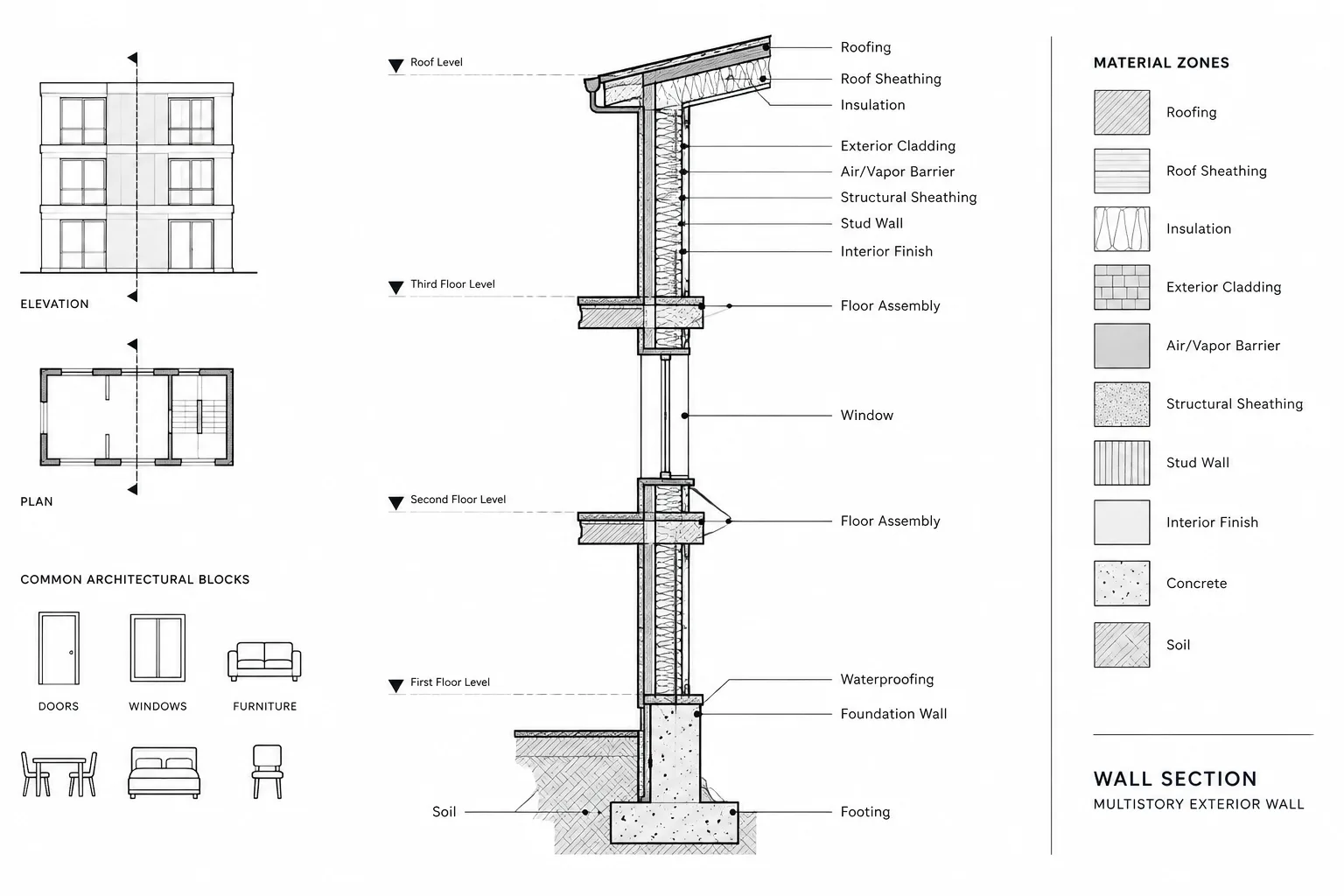
Architectural wall sections in CAD are most effective when treated as coordination drawings rather than isolated drafting exercises. They bring together information from plans, elevations, structural backgrounds, schedules, and enclosure details so vertical relationships can be reviewed in one place.
This guide presents a practical workflow for organizing that information, identifying conflicts, controlling graphic hierarchy, and deciding which conditions need enlarged details. It is intended as a drafting and coordination framework; project-specific assemblies still require review against verified design information, consultant documents, manufacturer instructions, and applicable requirements.
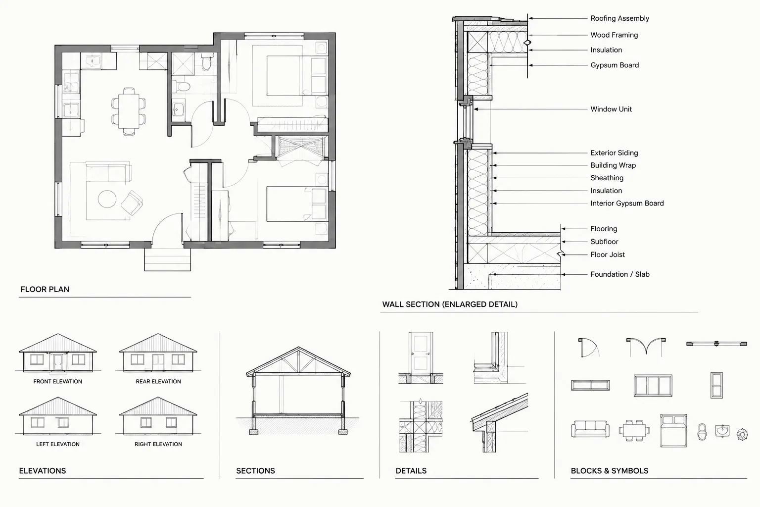
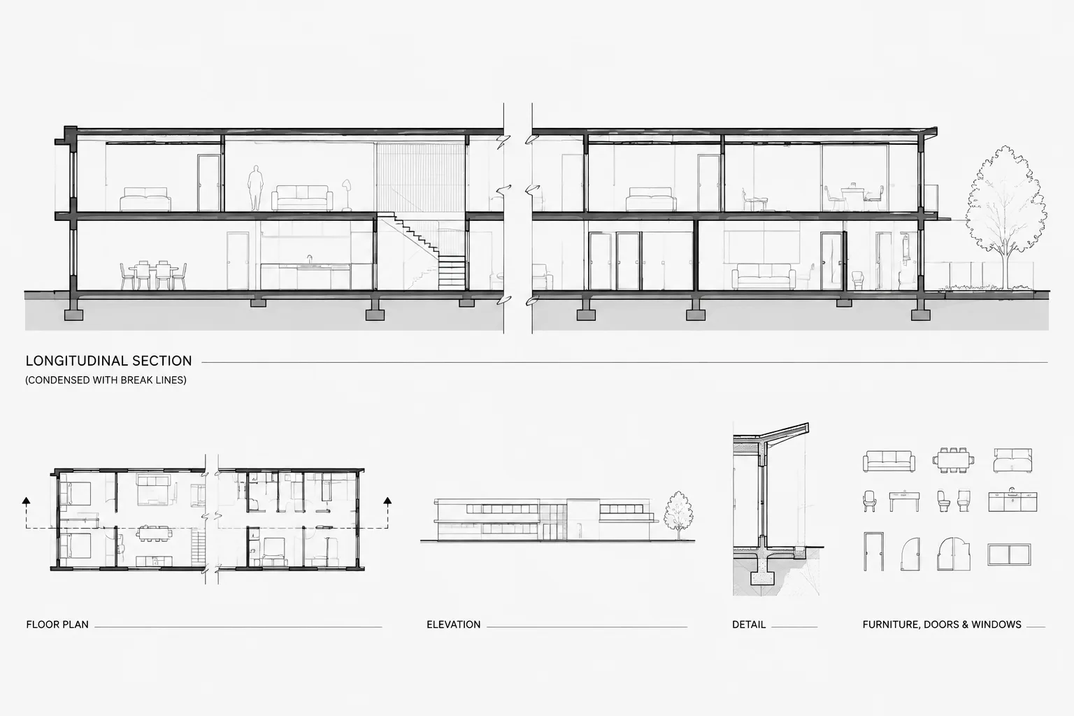
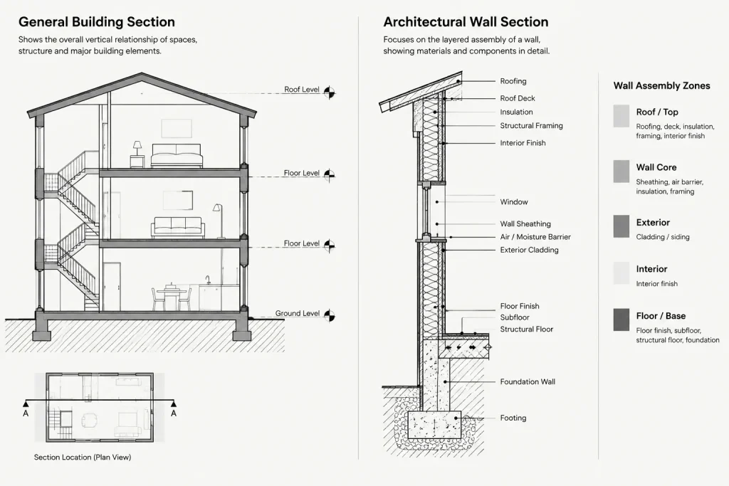
An architectural wall section explains how the building enclosure, structure, floors, roof, openings, and interior construction relate vertically. Unlike a general building section, which emphasizes spatial organization, a wall section concentrates on assembly relationships and the transitions that may require enlarged details.
Producing a useful wall section is not simply a matter of copying lines from plans and elevations. The drafter must reconcile information from several drawings, establish a clear graphic hierarchy, and identify where design intent still needs confirmation. The following workflow focuses on creating coordinated architectural wall sections in CAD without treating the drawing as a substitute for engineering, manufacturer instructions, or project-specific code review.
What a Wall Section Should Communicate
A wall section should help the reader understand the continuous vertical path through the building. Depending on the project, that path may extend from the foundation or lowest occupied level through intermediate floors and terminate at a roof, parapet, eave, or upper enclosure condition.
The drawing typically communicates:
- Floor, roof, ceiling, and grade relationships
- Exterior and interior wall assembly zones
- Structural elements shown for coordination
- Window and door relationships to adjacent construction
- Changes in materials, thicknesses, and alignment
- Drainage, air, vapor, and thermal control concepts where documented
- Locations that require enlarged details
- Vertical dimensions, levels, and references to related drawings
The wall section should show enough information to explain these relationships while reserving small interfaces, fasteners, sealant joints, flashing terminations, and similar construction information for appropriately scaled details.
Gather the Source Drawings Before Drafting
Begin with the current coordinated drawing set rather than drafting the section from the floor plan alone. A reliable wall section commonly draws information from architectural plans, elevations, roof plans, reflected ceiling plans, structural backgrounds, door and window information, and applicable enclosure details.
Review the source material for conflicts before tracing anything. Check whether floor levels agree across plans and elevations, whether the roof edge matches the roof plan, and whether openings align with the intended wall assembly. If consultants have issued updated backgrounds, confirm that the section is based on the current files.
| Source | Information to verify | Common coordination issue |
|---|---|---|
| Floor plans | Wall locations, openings, grids, and adjacent spaces | Section cut misses the intended opening or wall condition |
| Exterior elevations | Material changes, heads, sills, roof edges, and grade | Visible exterior joints do not align with section geometry |
| Roof plan | Slopes, drainage zones, parapets, and overhangs | Section shows a simplified roof edge that conflicts with drainage intent |
| Structural drawings | Framing depth, slab edges, foundations, and support locations | Architectural finishes occupy the same space as structural members |
| Schedules and details | Assembly identifiers, opening types, and finish references | Tags or notes refer to outdated construction |
Choose a Section Cut That Reveals Useful Conditions
A wall section should pass through a representative and informative part of the building. A cut through an opening can explain head, sill, floor, and roof relationships, while a cut through an uninterrupted wall may better describe a typical assembly. Complex projects may need more than one wall section because a single cut cannot clearly represent every facade, roof edge, or foundation condition.
Avoid forcing unrelated conditions into one supposedly typical section. If the enclosure changes between building areas, identify separate conditions and connect each section to the correct plan location. The section marker, viewing direction, drawing number, and sheet reference should remain coordinated as the drawing set develops.
Build the Section from Major Datums
Establish levels first
Start with the primary vertical references: floor levels, roof levels, grade, and other project datums. Use the same level naming and elevation basis employed elsewhere in the drawing set. These references form the framework for the section and make later coordination more reliable.
Do not adjust a level locally just to make the section look correct. If the plan, elevation, and structural background disagree, record the discrepancy and resolve it at the source.
Place structural zones
Next, show the major slabs, framing zones, foundations, bearing elements, and roof structure needed to explain the architectural assembly. Structural information in an architectural section is generally included for coordination and context. It should not imply that the architect has designed structural sizes or connections unless that responsibility is explicitly established and verified.
Add enclosure and finish zones
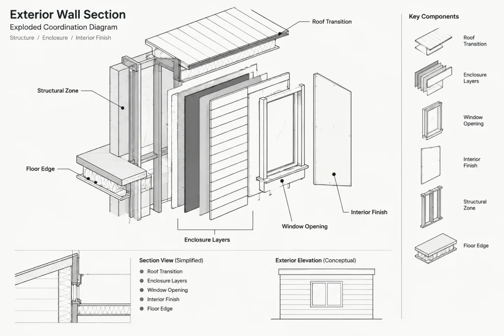
Build outward and inward from the primary structure. Represent the major components of the wall, roof, floor edge, and interior finish as distinct zones. At a smaller wall-section scale, material zones and boundaries are usually more readable than a dense collection of construction lines.
Use consistent wall type references and avoid manually recreating an assembly differently in multiple sections. When the design changes, update the source wall type information and review every section and detail that relies on it.
Trace Continuity Through Transitions
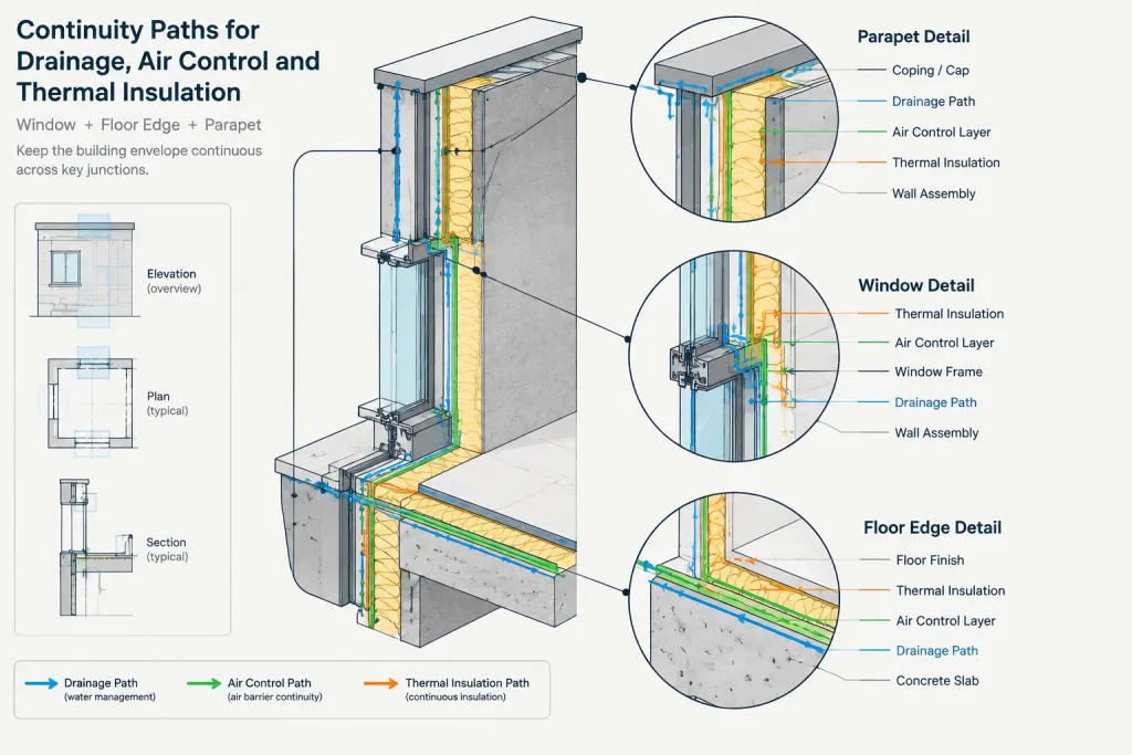
One of the most useful wall-section checks is to follow each enclosure function through the drawing. Rather than evaluating only the middle of the wall, trace the assembly across floor edges, openings, roof transitions, parapets, foundations, and changes in cladding.
Review the intended continuity of:
- Water-shedding and drainage layers
- Air-control layers
- Thermal insulation
- Vapor-control components where required by the verified design
- Interior and exterior finish support
These functions may be provided by different materials in different parts of the assembly. The section should reveal where one component transitions to another. If the transition cannot be explained at wall-section scale, place an enlarged detail callout at that location.
Coordinate Openings and Floor Edges
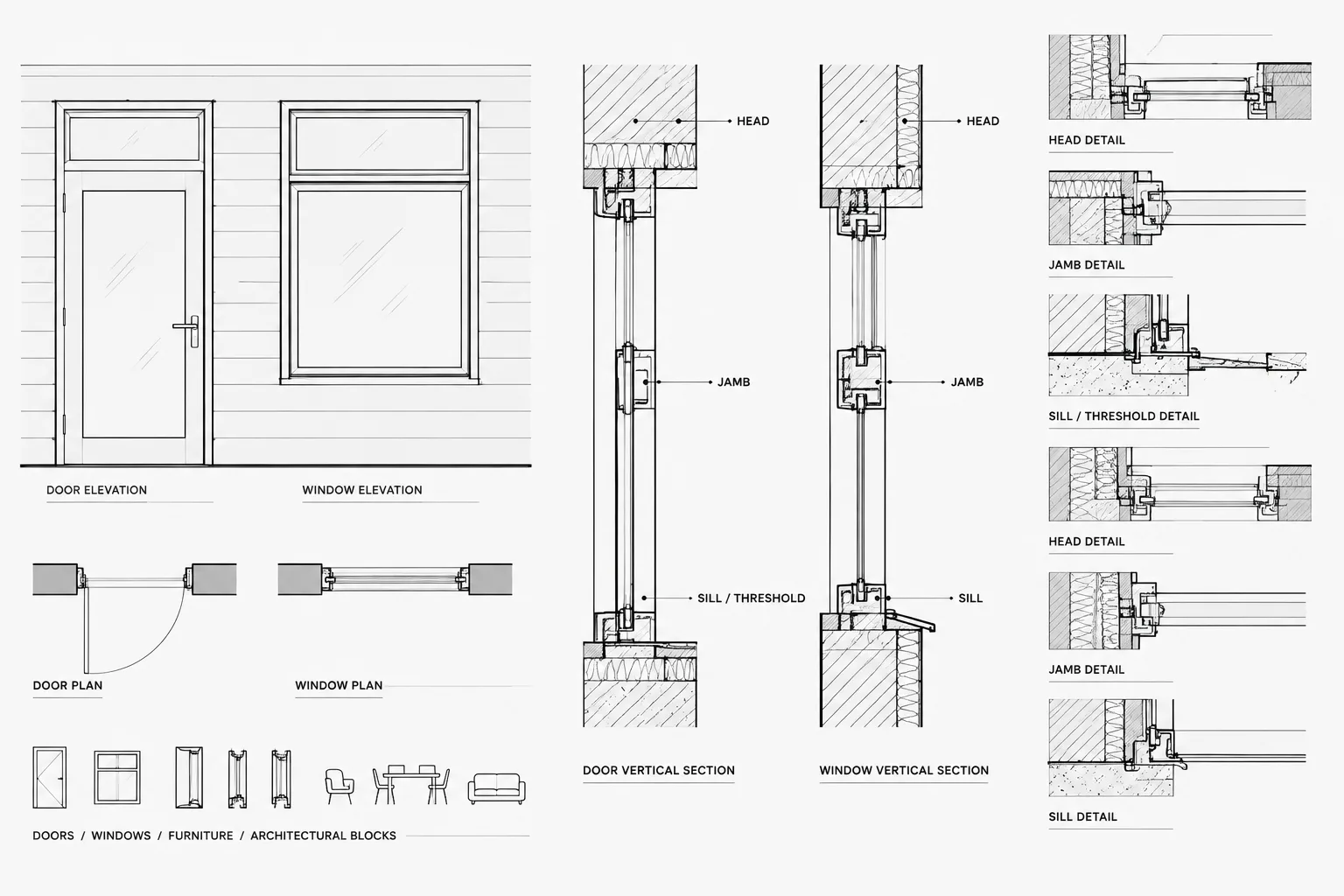
Openings often expose coordination problems because they involve the wall assembly, frame, glazing or door system, interior finish, exterior trim, flashing, and structure. In the wall section, show the opening in its correct relationship to floor levels, ceilings, and exterior materials. Use separate head, jamb, sill, or threshold details when the interfaces require more information.
At floor lines, check the relationship among the slab or framing edge, exterior wall, insulation, cladding support, ceiling, and interior partition. A clean graphic alignment is not necessarily a constructible alignment. Confirm what supports each component and whether there is enough space for the documented assembly.
Use a Clear CAD Graphic Hierarchy
Lineweight should make the section readable before the reader studies its notes. Elements cut by the section plane generally receive the strongest emphasis. Visible elements beyond the cut use lighter lines, while surface patterns, grids, dimensions, and reference information remain subordinate.
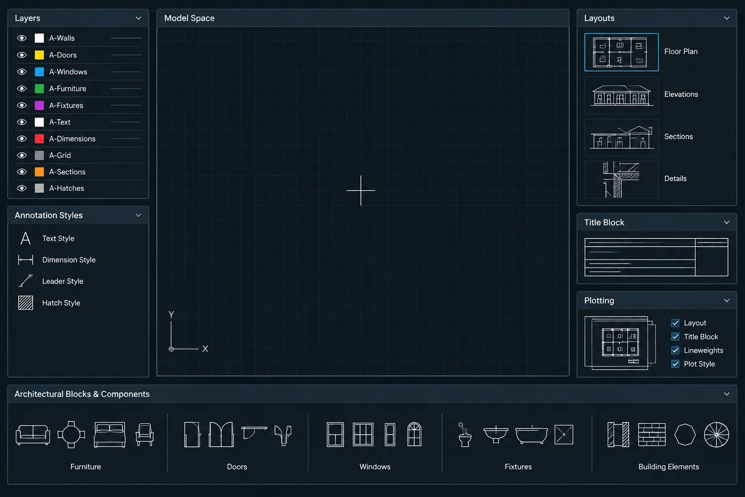
Organize section geometry, hatches, annotations, dimensions, grids, and consultant backgrounds on appropriate layers. Avoid placing all linework on a single section layer. A structured layer approach makes plotting, editing, and background management easier.
Use hatches selectively. Dense material patterns can obscure narrow assembly zones and detail references. If a material cannot be represented clearly at the drawing scale, identify it with a concise note, key, or wall type reference rather than forcing an unreadable pattern into the section.
Decide What Belongs in an Enlarged Detail
A wall section establishes relationships; a detail explains an interface. Move information to an enlarged detail when the wall-section scale cannot clearly show component terminations, laps, joints, attachment concepts, or transitions.
Typical detail callout locations include:
- Foundation-to-wall transitions
- Floor edges and shelf conditions
- Window and exterior door perimeters
- Canopies, balconies, and projecting elements
- Roof edges, parapets, and eaves
- Changes in cladding or wall construction
- Transitions between occupied and unoccupied zones
Keep callouts close enough to the relevant condition that their meaning is obvious. Confirm that every referenced detail exists, uses the correct orientation, and represents the actual condition shown in the section.
Annotate Without Duplicating Conflicting Information
Use notes to identify assemblies, materials, and coordination intent, but avoid repeating specifications or schedules throughout the drawing. Repeated information can become inconsistent when revisions occur.
Dimensions should focus on important vertical relationships and project control points. Coordinate level markers with the project datum, and distinguish between dimensions needed to locate construction and references that merely describe it. If a dimension depends on a product, structural design, or code requirement, confirm it through the appropriate verified source before documenting it.
Wall Section Quality-Control Checklist
- Confirm that the section cut and viewing direction match the plan marker.
- Compare all floor, roof, and grade levels with plans and elevations.
- Verify wall, floor, and roof assembly identifiers.
- Check openings against the current door and window information.
- Review structural backgrounds for slab edges, beams, framing, and foundations.
- Trace enclosure continuity through openings and major transitions.
- Confirm that detail callouts point to existing and applicable details.
- Remove obsolete linework, duplicate notes, and abandoned options.
- Test the plotted lineweight and hatch hierarchy at the intended sheet scale.
- Flag unresolved code, product, structural, or consultant-dependent information.
Treat the Wall Section as a Coordination Drawing
The best architectural wall sections are developed alongside the plans, elevations, schedules, and details rather than at the end of documentation. As the design changes, the section becomes a useful test of whether the building still fits together vertically.
A disciplined CAD workflow begins with verified datums, builds from major structure to enclosure zones, traces critical continuity, and delegates small interfaces to coordinated details. The result is a wall section that is easier to read, easier to revise, and more valuable to the entire drawing set.
Managing Wall Section Revisions in CAD
A coordinated wall section must remain traceable as the project develops. When a floor level, opening, roof edge, structural zone, or wall assembly changes, review the related plan, elevation, schedule, and detail references rather than editing the section in isolation.
Record unresolved conditions
Use a project-approved issue-tracking method to distinguish confirmed geometry from information awaiting architectural, structural, enclosure, product, or code review. A visible coordination note is safer than drawing an unsupported condition as though it were resolved.
Review dependent drawings
Wall section revisions can affect opening details, exterior elevations, ceiling relationships, finish transitions, and assembly references. Search the drawing set for repeated tags and callouts whenever a referenced condition changes. This reduces the risk of leaving an older version elsewhere in the documents.
Control consultant backgrounds
Keep referenced backgrounds identifiable and avoid permanently tracing consultant information without a way to verify its origin. Before issuing a revised section, confirm that the displayed structural and site information comes from the current coordinated source.
Check the plotted drawing
Model-space organization alone does not guarantee a readable sheet. Review the section in its intended plotted context to confirm that cut elements remain dominant, hatches do not merge into solid areas, notes are legible, and callouts are visually connected to the correct conditions.
A Useful Final Review Question
Before considering the section complete, ask whether another project team member can follow the assembly from the lowest shown condition to the roof without guessing which drawing controls a transition. Where the path becomes unclear, revise the section, add a verified reference, or identify the need for further coordination.
Frequently Asked Questions About Architectural Wall Sections in CAD
What is the difference between a building section and a wall section?
A building section primarily explains overall spatial and vertical organization. A wall section concentrates on the relationship among structure, enclosure, floors, roofs, openings, finishes, and adjacent construction.
Should every construction component appear in a wall section?
No. The drawing should show the major zones and relationships that remain readable at its presentation scale. Small terminations, joints, attachments, and interface conditions are generally better communicated through coordinated enlarged details.
Should structural information be copied into the architectural section?
Structural elements may be shown as coordination context, but they should come from current verified information. Their appearance in an architectural section should not imply responsibility for structural design or connection engineering.
How should unresolved conflicts be shown?
Do not hide a conflict by adjusting geometry only in the section. Record the issue through the project’s coordination process, identify the controlling source, and update affected drawings after the condition is resolved.
When does a wall section need a separate detail callout?
Add a detail callout when an interface cannot be clearly explained at wall-section scale. Common examples include opening perimeters, floor edges, foundation transitions, roof edges, parapets, projections, and changes between enclosure systems.
How can CAD layers improve wall section coordination?
Separate cut geometry, elements beyond, hatches, dimensions, notes, grids, references, and consultant backgrounds according to the project’s layer system. This supports clearer plotting, selective display, revision work, and background management.