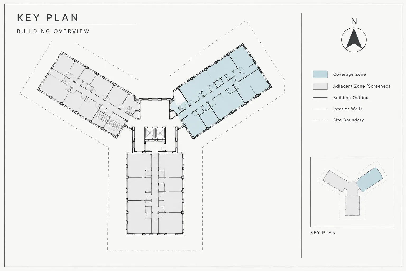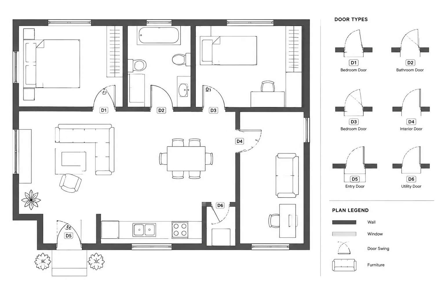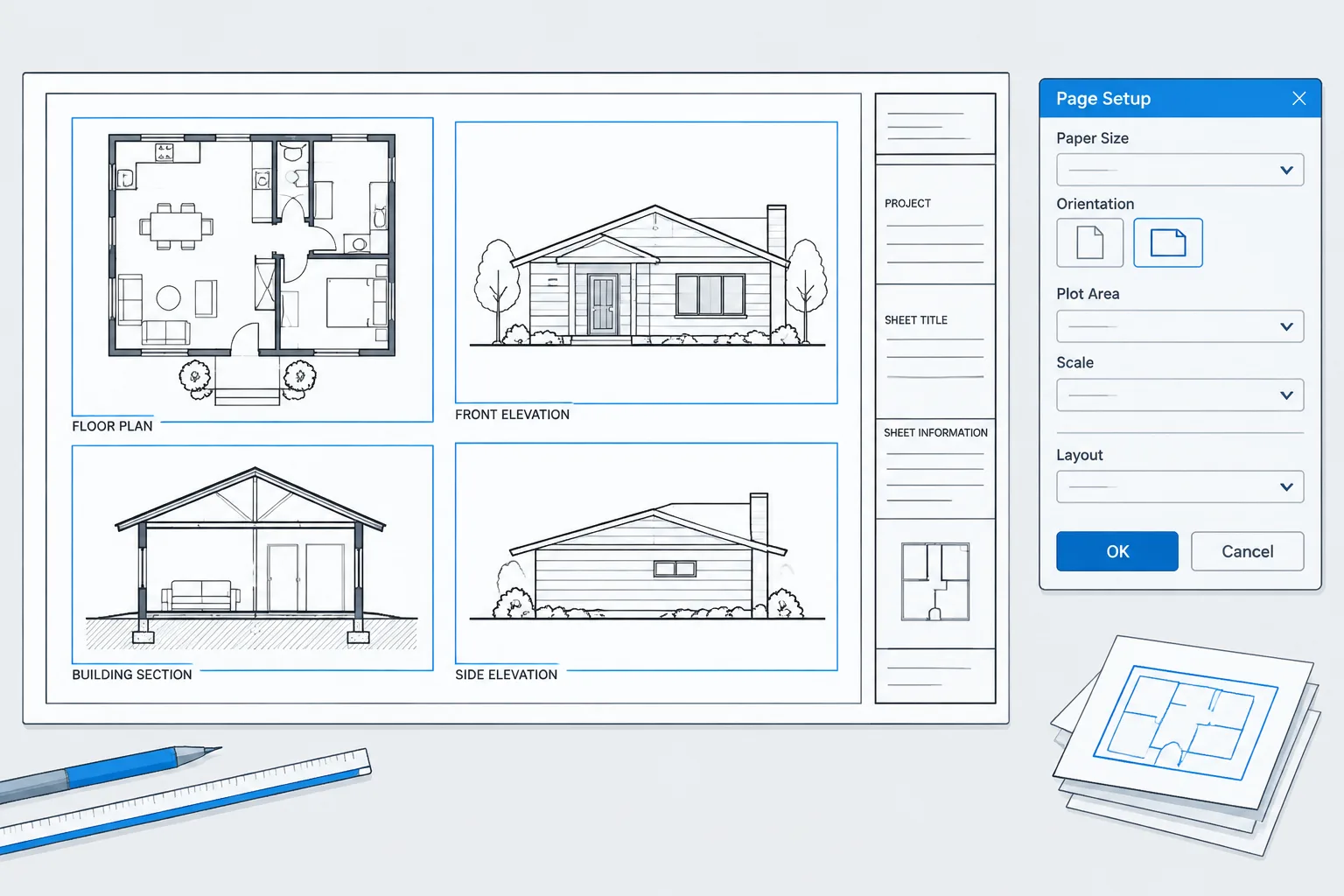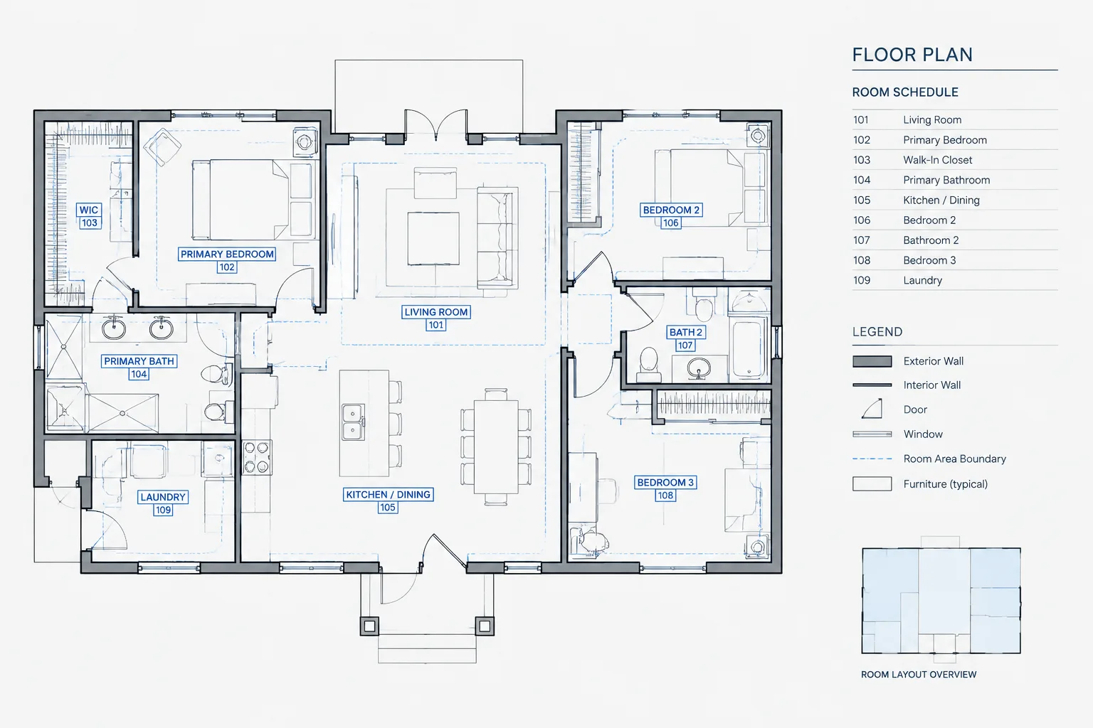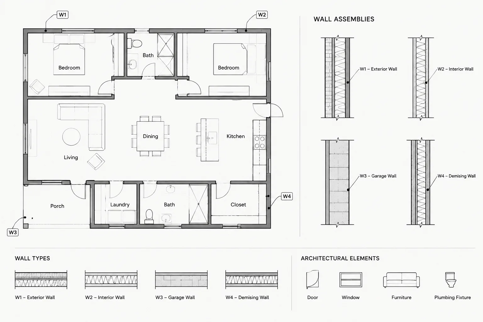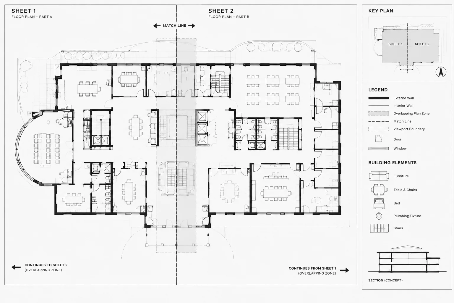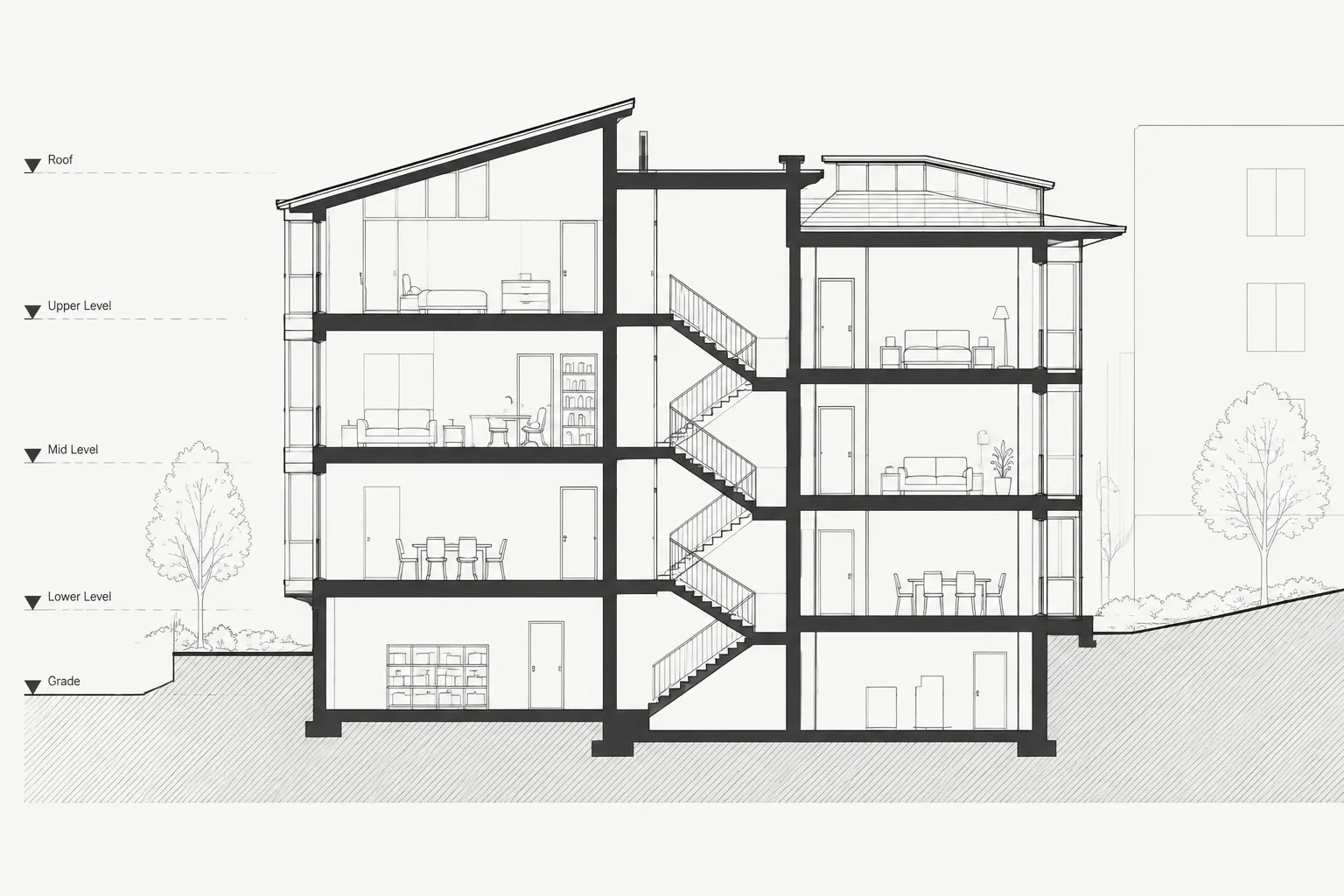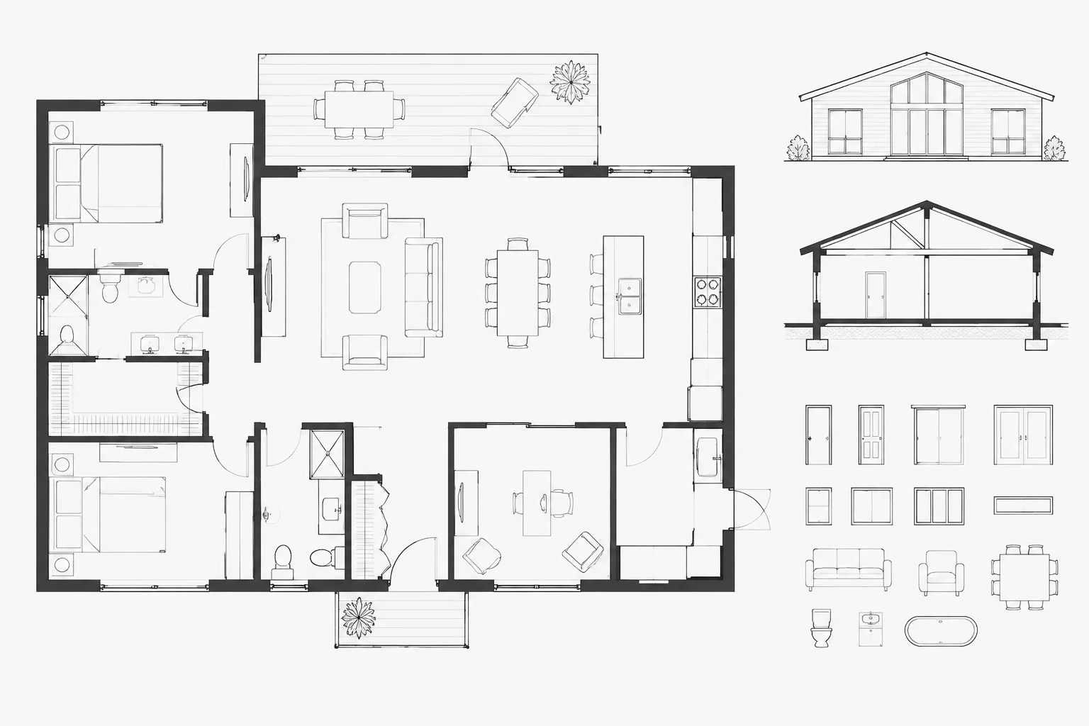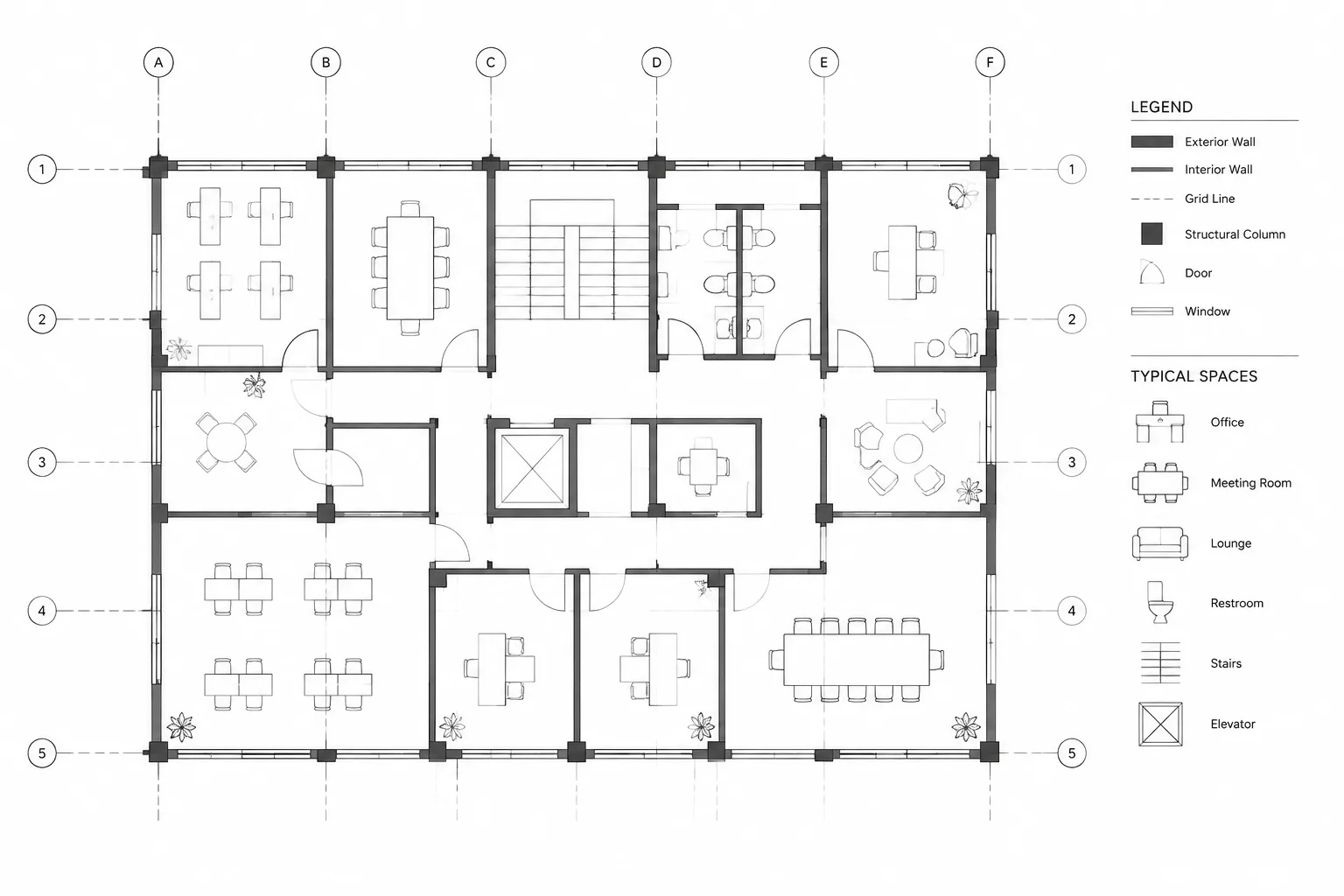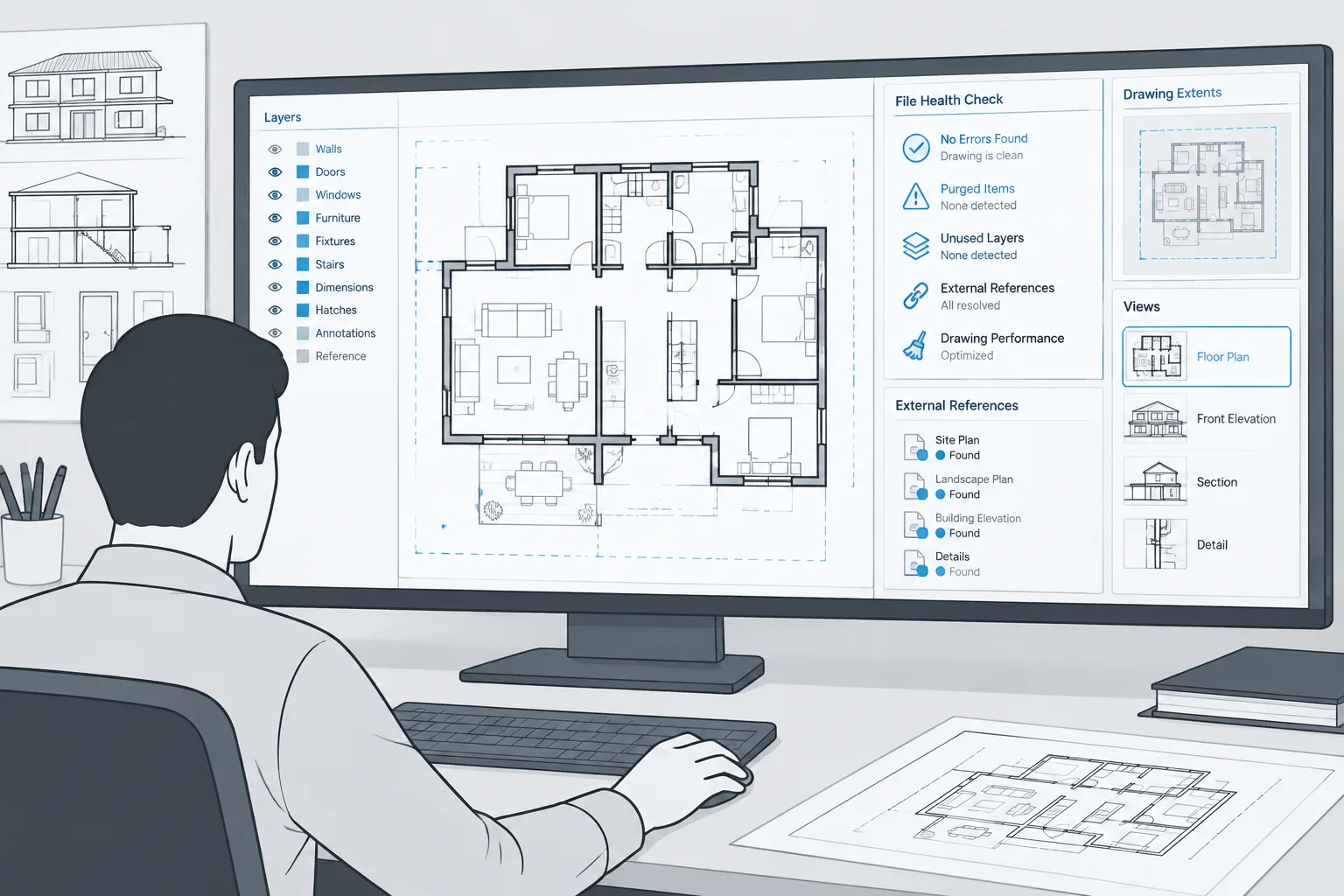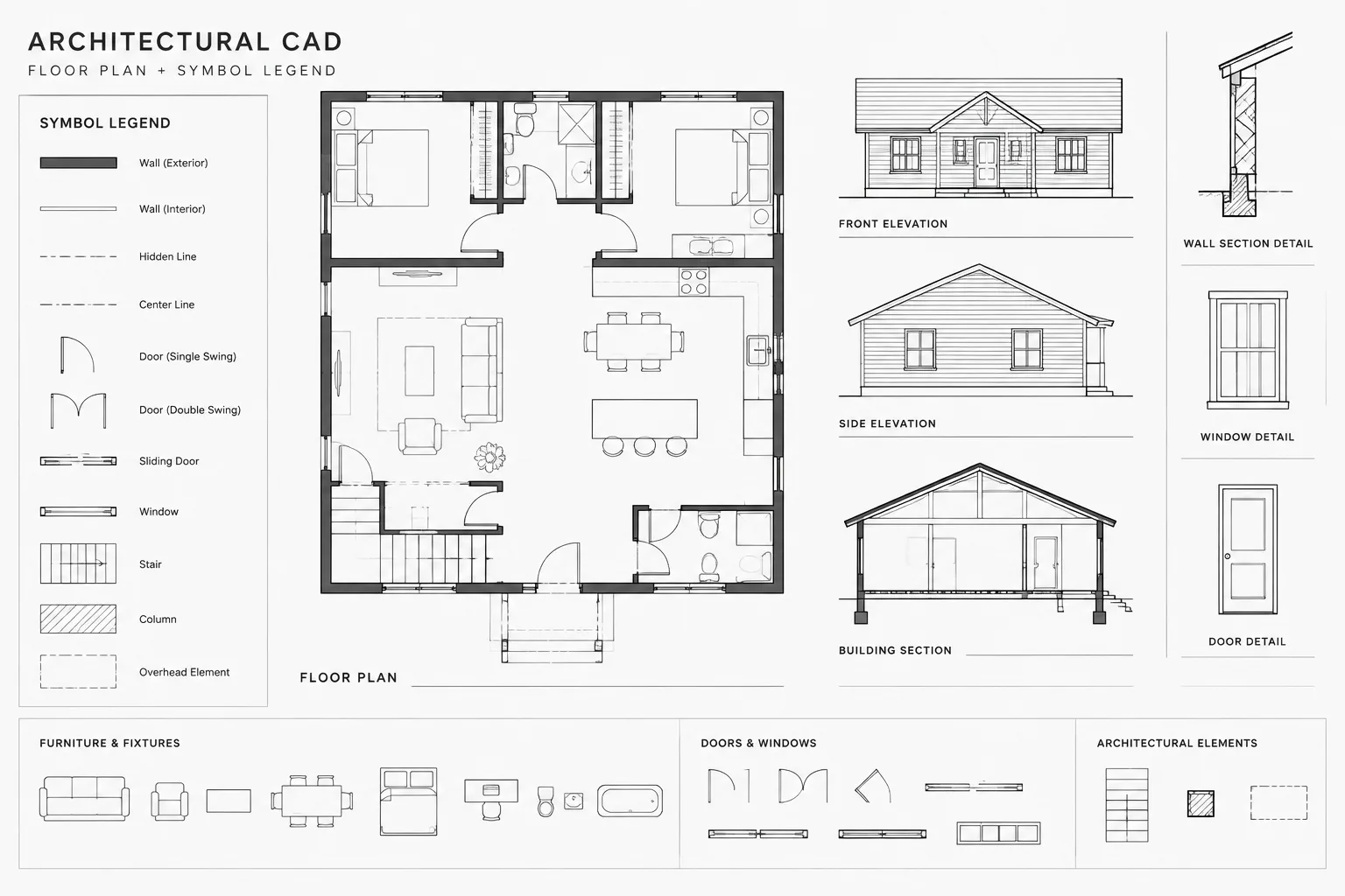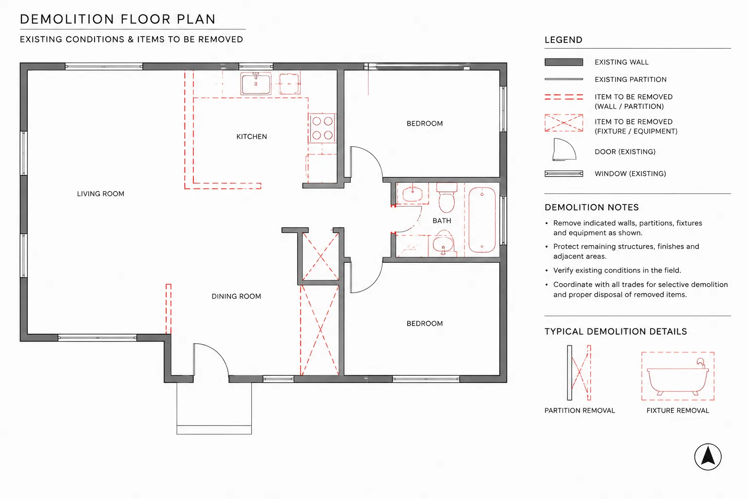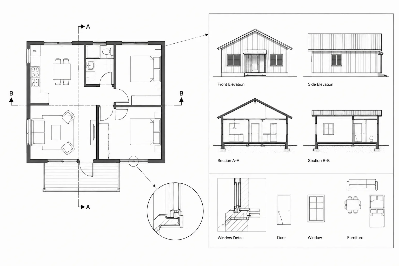
Architectural section and detail callouts form the navigation system of a drawing package. Each marker must connect a specific source condition to the correct destination view while remaining legible among dimensions, grids, tags, hatches, and model geometry.
This guide focuses on the coordination decisions behind reliable callouts: selecting the correct reference type, controlling CAD blocks and attributes, communicating view direction and extent, managing layers, and checking references after drawings move. Use it as a workflow framework, then apply the graphic conventions, naming rules, and sheet organization established for the project.
Architectural section and detail callouts do more than identify where another drawing can be found. They connect plans, elevations, sections, enlarged views, and construction details into a navigable drawing set. When those references are inconsistent, readers may arrive at the wrong view, search for a detail that has moved, or miss the intended direction of view.
A dependable callout workflow therefore requires more than placing symbols. The CAD team must control the marker geometry, reference information, viewing direction, source location, and destination drawing as coordinated data. This guide explains how to establish that workflow without tying it to a particular office standard or sheet-numbering system.
What a callout must communicate
A useful callout answers several questions at a glance:
- What type of view is being referenced?
- Where does the referenced view originate?
- Which direction does the view look?
- What is the drawing or detail identifier?
- On which sheet can the destination be found?
- Does the marker refer to a complete cut, a partial view, or a limited area?
The exact graphic convention varies by office and project. Some markers combine the drawing identifier and sheet reference in one symbol, while others separate them. The important requirement is internal consistency. A reader should not have to interpret several unrelated symbol systems within the same drawing set.
Distinguish the main reference types
Callouts should reflect the type and extent of the view they create. Reusing one generic marker for every condition can obscure important information.
| Reference type | Typical source | Information to communicate |
|---|---|---|
| Building section | Floor plan or roof plan | Cut location, viewing direction, section identifier, and destination sheet |
| Wall or partial section | Plan, building section, or elevation | Localized cut, direction, identifier, and destination |
| Exterior or interior elevation | Plan or enlarged plan | Viewing direction, elevation identifier, and sheet reference |
| Detail callout | Plan, section, elevation, or another detail | Boundary or point of interest, detail identifier, and destination sheet |
| Enlarged-plan callout | Overall floor plan | Area included in the enlarged view and its drawing destination |
A section marker normally represents a cut through the building or assembly. An elevation marker indicates a viewing direction without implying the same type of cut. A detail callout may identify a bounded area, a connection, or a specific construction condition. Keeping these meanings distinct helps readers understand the relationship before opening the referenced sheet.
Build a controlled CAD symbol system
Create callout graphics as managed blocks rather than repeatedly drawing circles, lines, arrows, and text as separate objects. A block keeps the symbol together and reduces accidental changes to its proportions or text arrangement.
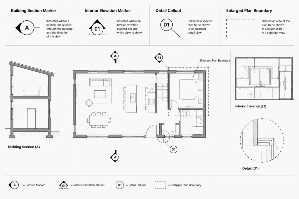
A practical callout block may include:
- Consistent marker geometry
- An obvious viewing-direction indicator where applicable
- Attributes for the drawing or detail identifier
- An attribute for the destination sheet
- Optional status information used by the project team
- A logical insertion point that supports predictable placement
Use a small, documented family of blocks instead of creating a new variation for each sheet. Separate block definitions may be appropriate for building sections, wall sections, elevations, and detail bubbles because their graphics perform different jobs. Avoid nearly identical duplicate definitions with unclear names.
Choose insertion points intentionally
The insertion point should correspond to the part of the marker that users are most likely to position accurately. For an elevation marker, that may be the center of the symbol. For a section head, it may be the point where the head meets the cut line. For a detail boundary, the boundary and reference tag may need to be separate coordinated objects if one fixed insertion point would make editing awkward.
Test insertion, rotation, mirroring, and stretching before releasing a block to the project team. Text should remain readable, arrows should continue to indicate the intended direction, and attributes should not become reversed or detached from the symbol.
Separate marker graphics from cut or view limits
A section reference often has two related components: the identifying marker and the line showing where the cut occurs. A detail reference may combine a boundary with a tag and leader. These components should be easy to edit without losing their relationship.
Do not let a section line visually disappear into walls, grids, dimensions, or hatch patterns. Adjust the marker position and surrounding annotation so the path can be followed. At the same time, avoid extending the line farther than necessary, especially when a partial section is intended. The graphic extent should honestly describe what the destination drawing shows.
For enlarged-plan callouts, draw a clear boundary around the included area. Check that the enlargement actually covers the indicated region and that important adjacent conditions are not implied to be included when they are absent from the destination view.
Use a source-and-destination workflow
Every callout creates a two-part relationship:
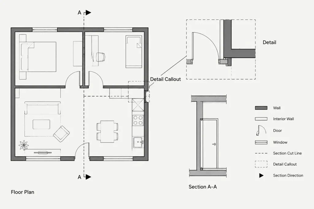
- Source: the plan, elevation, section, or detail containing the callout marker.
- Destination: the referenced drawing located elsewhere in the set.
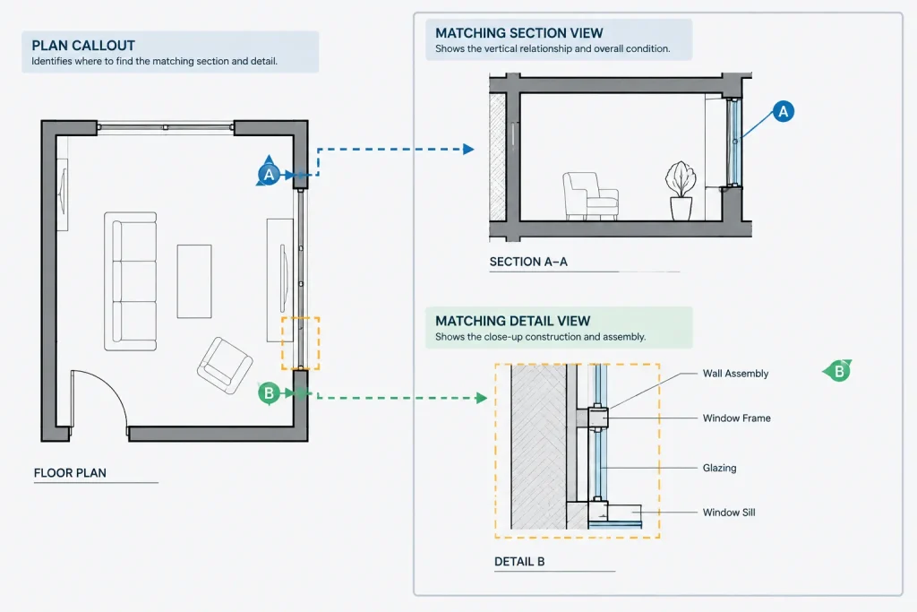
Both sides must be checked. A correctly formatted marker is still wrong if the destination drawing has a different identifier. Likewise, a well-labeled detail may be effectively orphaned if no source view points to it.
A reliable sequence is to establish the destination view, assign its identifier and sheet location, and then update every source marker. If the destination is moved, review its incoming references immediately rather than waiting for a final sheet check. Temporary placeholders can be useful during development, but they should be visibly distinguishable from completed references and resolved before issue.
Place callouts on appropriate layers
Callout markers should be separated from model geometry so their visibility and plotted appearance can be controlled. An office may use one annotation layer for references or separate layers by marker type. Either approach can work if it is documented and consistently applied.
Confirm that the chosen layers:
- Plot with sufficient contrast against plans and hatches
- Remain visible in the viewports where the callouts are needed
- Can be hidden from views where they would be redundant
- Are not confused with nonplotting construction or coordination layers
- Follow the project’s property strategy rather than relying on isolated object overrides
Viewport-specific layer control can help when one model-space plan supports several sheet views. However, hidden callouts can also create coordination risks. Include viewport visibility in the checking process instead of assuming that a marker visible in model space will appear on every intended sheet.
Plan for crowded drawing areas
Callouts frequently compete with dimensions, room tags, door numbers, grids, and other references. Move a marker only when its relationship to the source remains unmistakable. Long or crossing leaders can make the drawing harder to follow than a carefully repositioned tag.
Where several references occur close together, establish a clear reading order. Align related markers when practical, provide spacing around attribute text, and avoid placing symbols directly over critical geometry. Background masks may improve legibility in selected conditions, but they should not conceal information the reader needs to coordinate the view.
Coordinate identifiers without creating duplicates
Drawing and detail identifiers need to be unique within the project’s chosen organizational system. Duplicate identifiers are particularly easy to create when details are copied between sheets or when several team members develop a package concurrently.
Before assigning a new identifier, check the destination sheet and any drawing index or tracking list used by the team. When copying a callout block, edit its attributes immediately. A copied marker that retains the original reference can look complete while directing readers to an unrelated drawing.
If attributes or fields are used to manage reference text, understand which values update automatically and which still require manual coordination. Automation can reduce repeated typing, but it does not verify that the marker points to the correct architectural condition.
Quality-control checks before issue
Review callouts from the plotted sheet set, not only from individual DWG files. The published output reveals viewport visibility, clipping, scale, lineweight, and readability issues that may not be obvious during model-space editing.
- Trace every source marker to an existing destination drawing.
- Confirm that the destination identifier and sheet reference match the marker.
- Check that section and elevation arrows face the intended direction.
- Verify that the view extent agrees with the source cut line or callout boundary.
- Look for duplicate drawing identifiers on each sheet.
- Find destination drawings that have no source reference where one is expected.
- Review markers near viewport crops and match lines for accidental truncation.
- Check attribute text for placeholders, blanks, or outdated sheet information.
- Confirm that rotated or mirrored markers remain readable.
- Inspect the final PDF at a realistic viewing size.
Treat callouts as navigation data
The most effective section and detail callouts are not merely graphic symbols. They are navigation links within the architectural drawing set. Their value depends on a clear relationship between the source condition, viewing direction, drawing identifier, and destination sheet.
By using controlled blocks, purposeful layers, consistent naming, and a source-to-destination review, CAD teams can reduce broken references and make complex drawing packages easier to use. The final test is simple: a reader unfamiliar with the file structure should be able to follow each marker to the correct view without guessing.
Apply the workflow throughout drawing development
Callout coordination should continue as the drawing set changes. A reference that was correct when placed may become outdated after a view is renamed, relocated, divided, combined, or removed. Treat every destination change as a reason to review the markers that lead to it.
Record the relationship, not just the label
A useful tracking method identifies the source drawing, the destination drawing, the reference type, and the person or team responsible for resolving any open condition. This makes it easier to distinguish a deliberate placeholder from an overlooked or broken reference.
Check references in both directions
Forward checking begins at a source marker and confirms that it reaches the intended destination. Reverse checking begins at a section, elevation, enlarged plan, or detail and asks where that view is referenced. Using both methods helps reveal incorrect labels as well as destination drawings that have become disconnected from the set.
Review after sheet composition
A marker can be correct in model space yet fail on the published sheet because of viewport cropping, layer visibility, nearby annotation, or poor contrast. Review the composed output whenever viewports or sheet layouts change. The check should include the callout symbol, its text, the indicated direction, the source condition, and the destination label.
A practical handoff standard
When several people edit the same package, agree on who may assign identifiers, who updates incoming references after a drawing moves, and how unresolved destinations are marked. Clear ownership reduces duplicate identifiers and prevents temporary references from appearing complete.
At handoff, avoid relying only on visual familiarity with the project. Another drafter should be able to select or inspect a marker, understand its purpose, locate its destination, and recognize whether it is complete. That test supports both drawing usability and future CAD maintenance.
Frequently asked questions
What is the difference between a section marker and a detail callout?
A section marker identifies a cut location and viewing direction through a building or assembly. A detail callout identifies a focused condition or bounded area that is shown elsewhere at greater specificity. Their graphics should communicate those different relationships.
Should every callout use the same CAD block?
Not necessarily. A controlled block family can preserve a consistent visual language while allowing distinct symbols for sections, elevations, enlarged plans, and details. The goal is to avoid unrelated or nearly duplicate block definitions that are difficult to manage.
Should callout information be stored as block attributes?
Attributes can keep identifiers and destination references attached to the marker and make editing more orderly. They do not, however, confirm that the referenced drawing exists or depicts the correct condition. The relationship still requires review.
How should copied callouts be handled?
Edit copied marker information as soon as the copy is placed. Leaving the original identifier or sheet reference in place can create a convincing but incorrect link to another drawing.
Why can a callout appear in model space but not on the sheet?
The marker may be affected by viewport-specific layer settings, viewport cropping, annotation visibility, plotting properties, or overlapping graphics. Check the composed sheet and published output rather than relying only on the editing view.
How can orphaned details be found?
Review destination drawings in reverse and identify the source marker expected to lead to each view. If no source can be found, determine whether the destination needs a reference, serves another documented purpose, or should be removed.