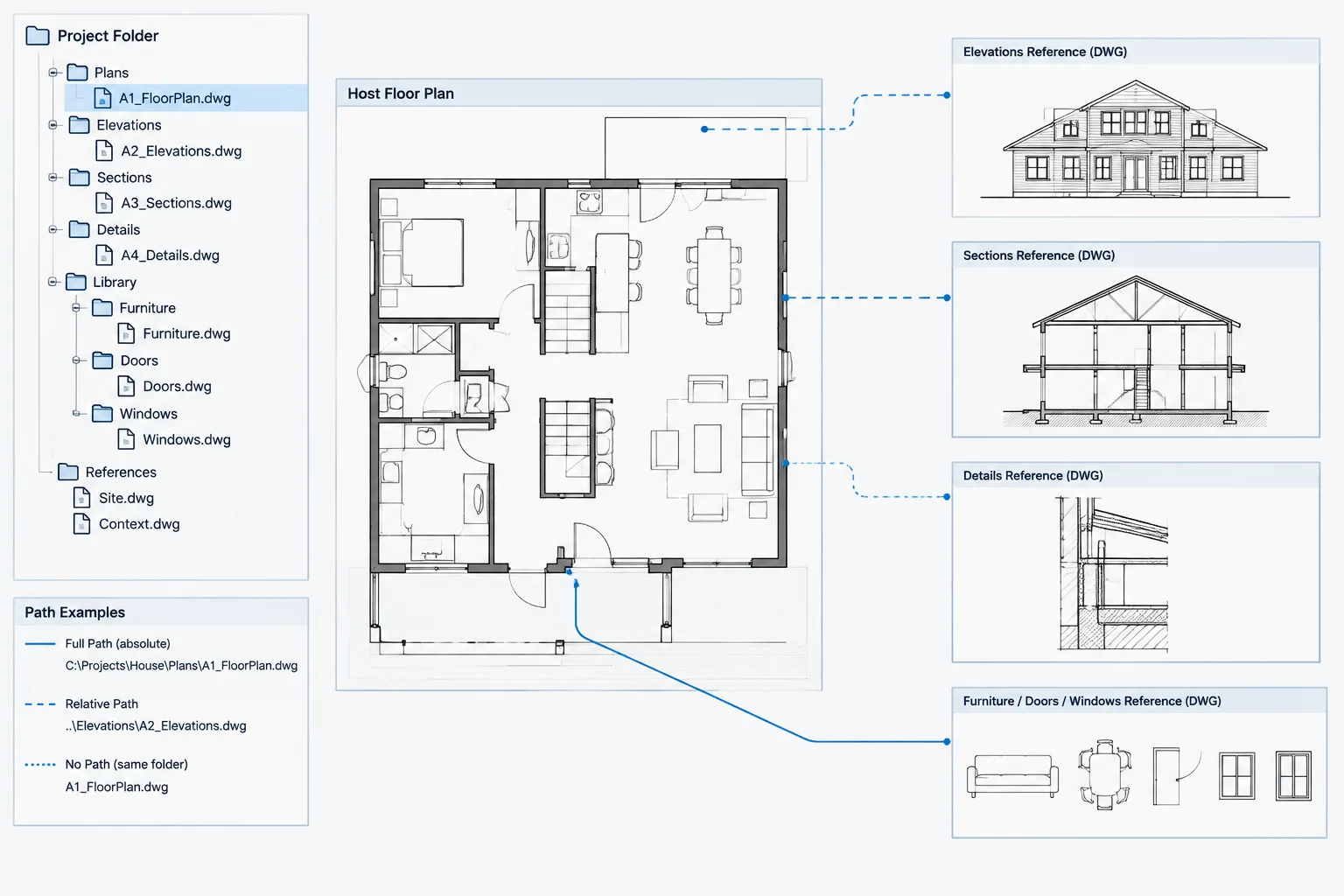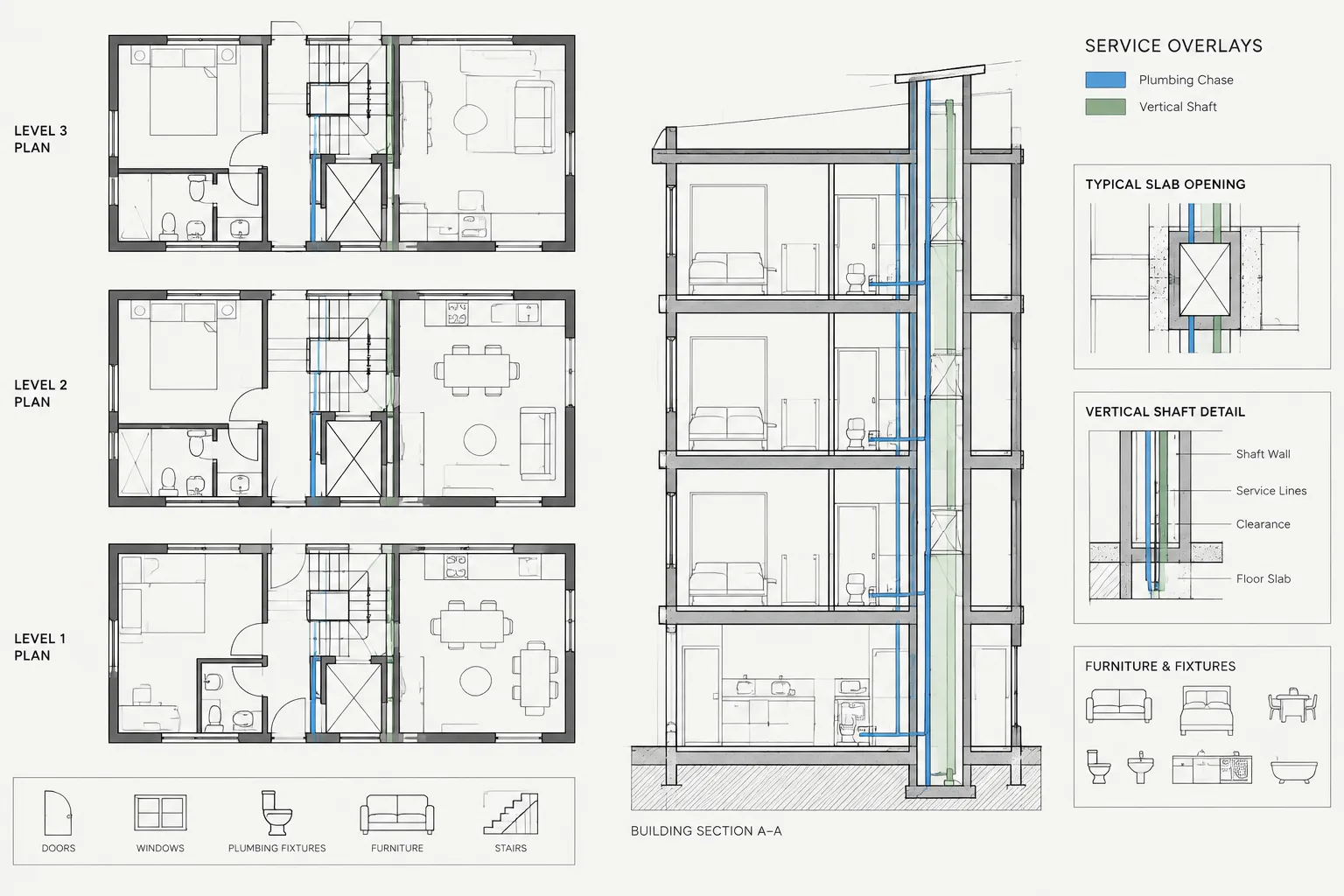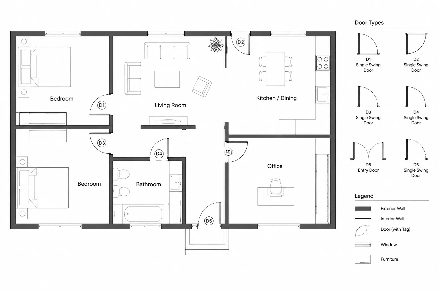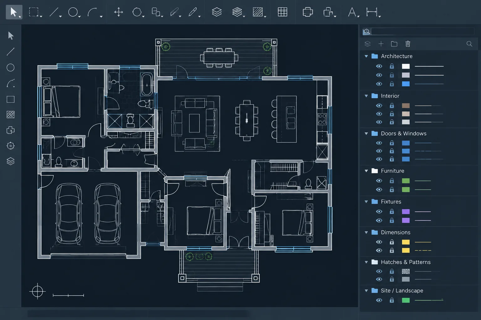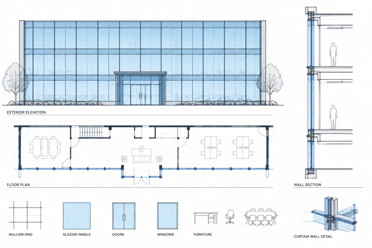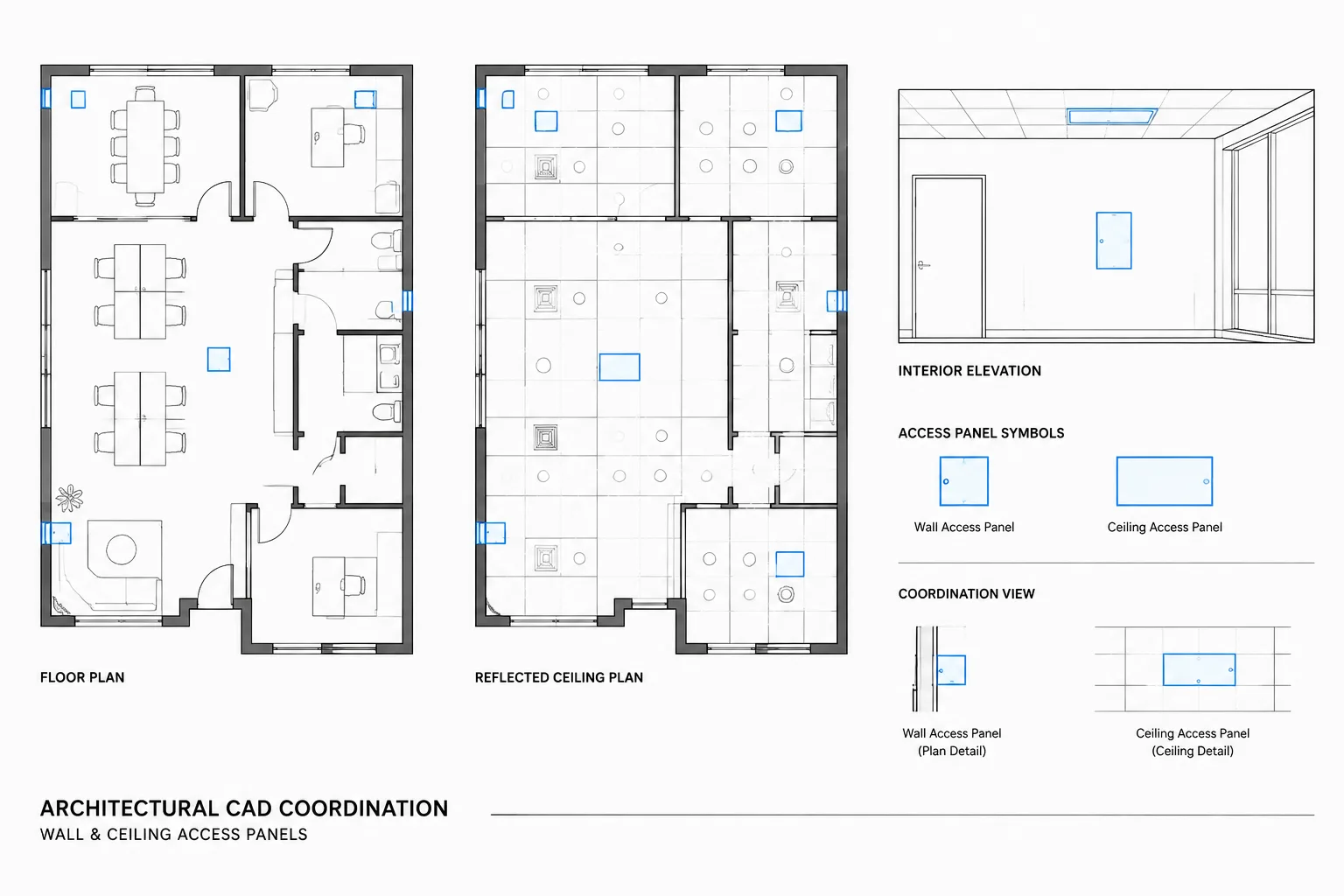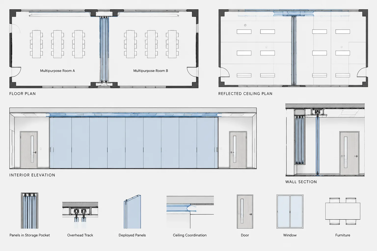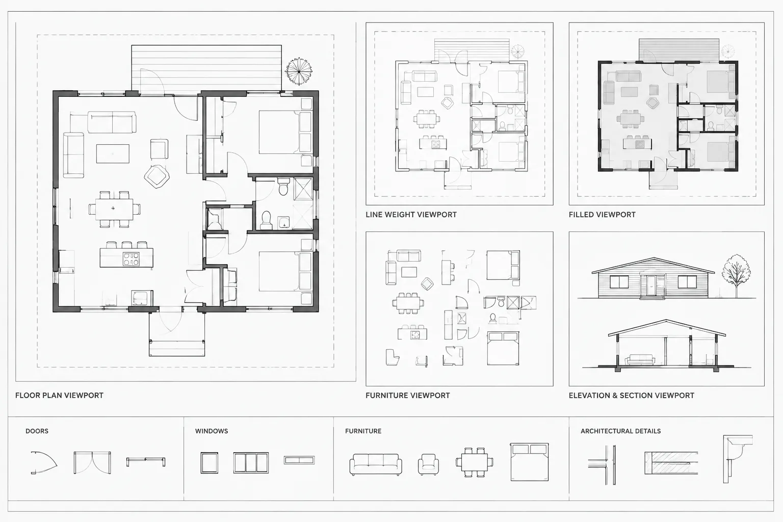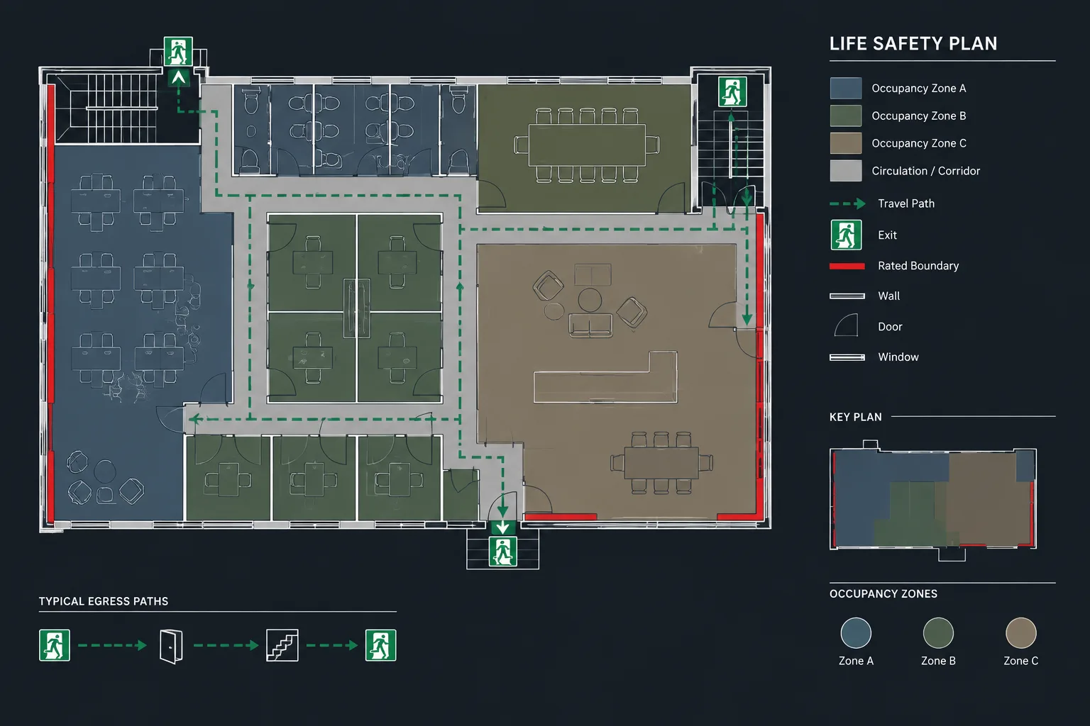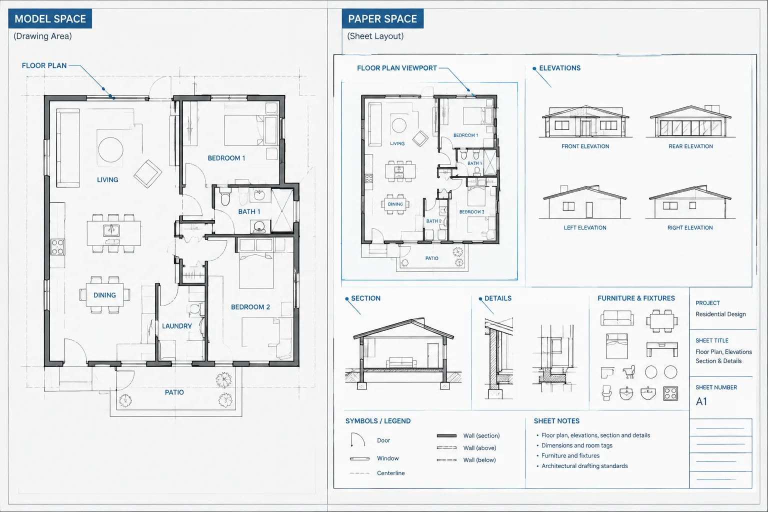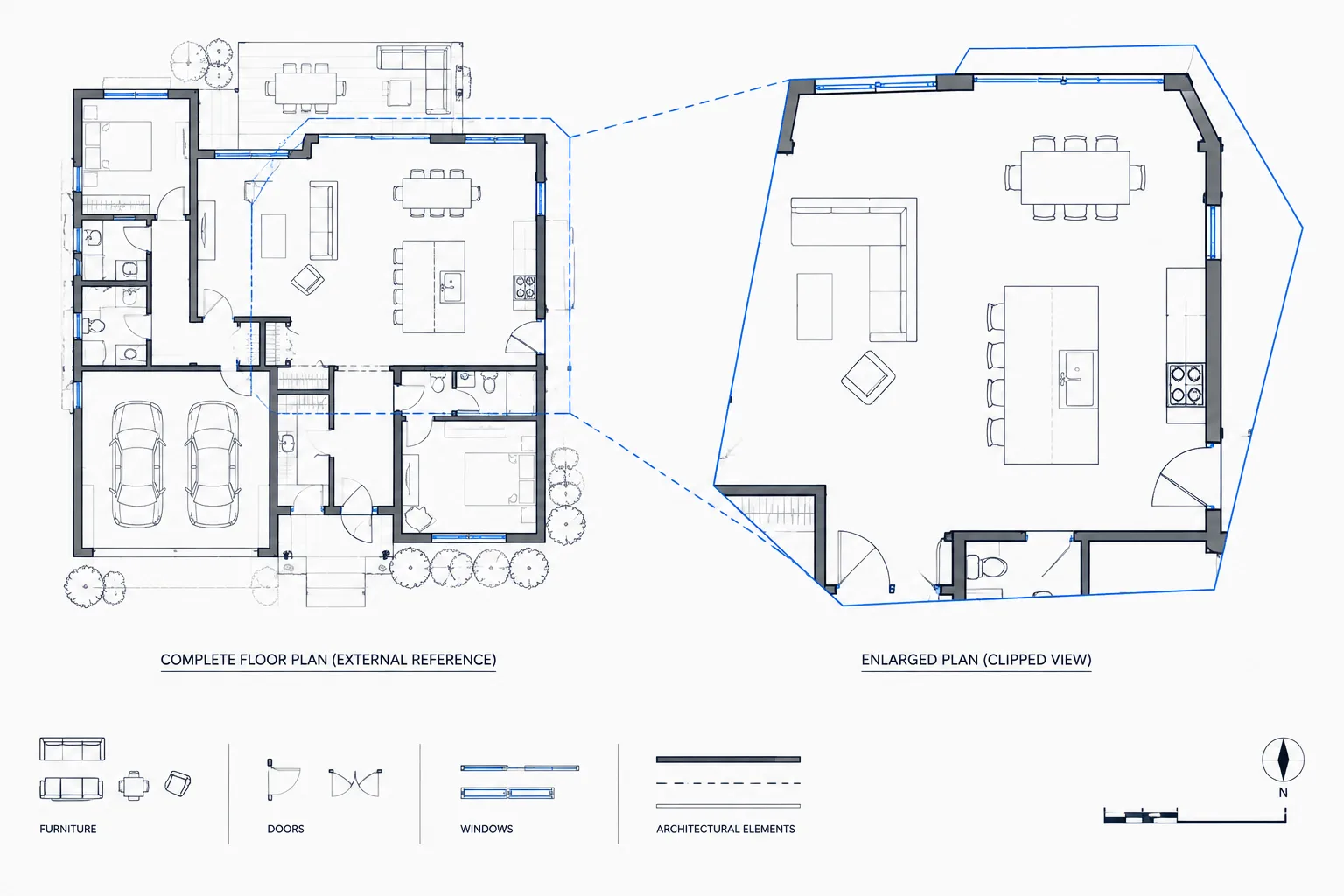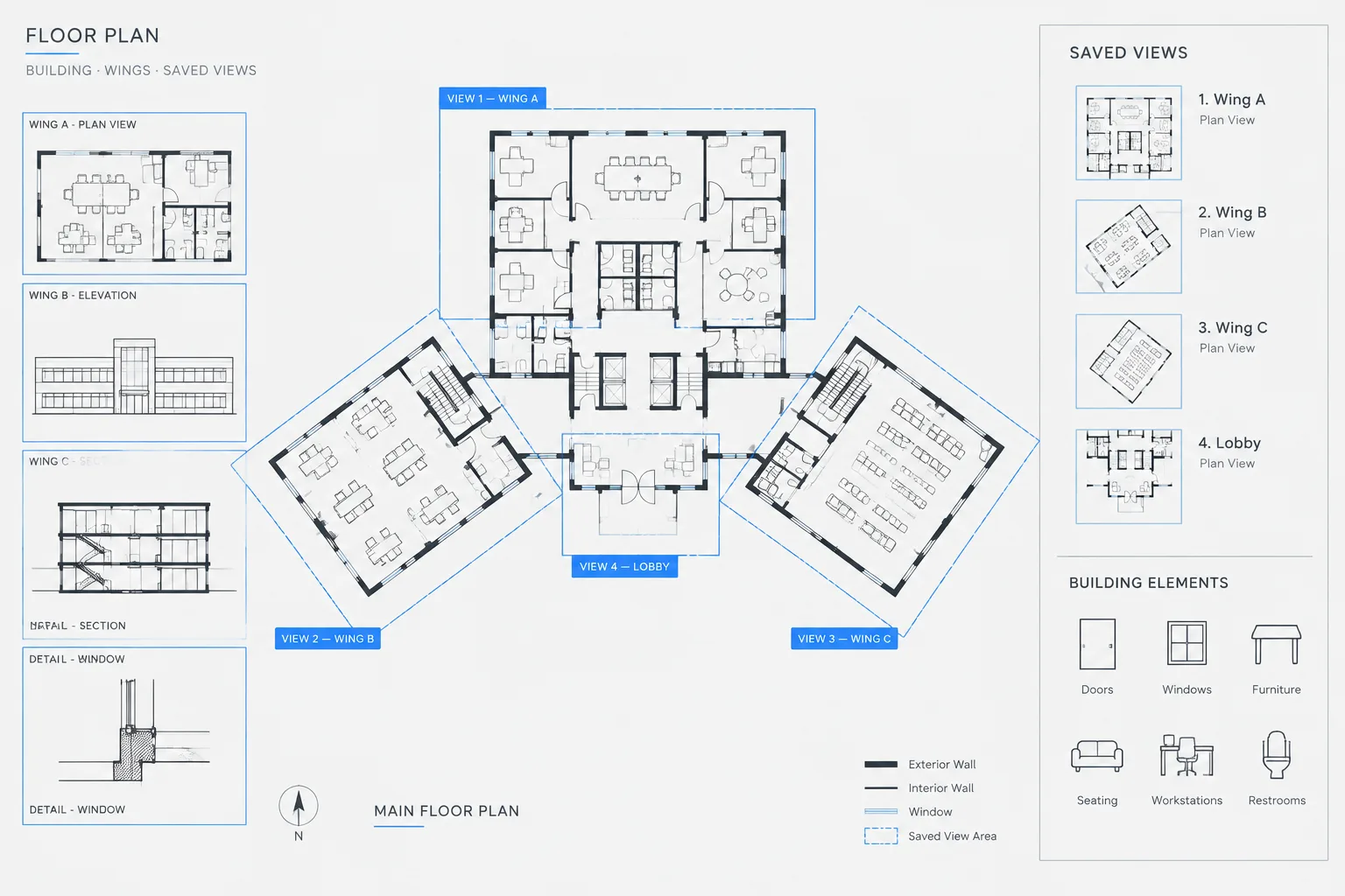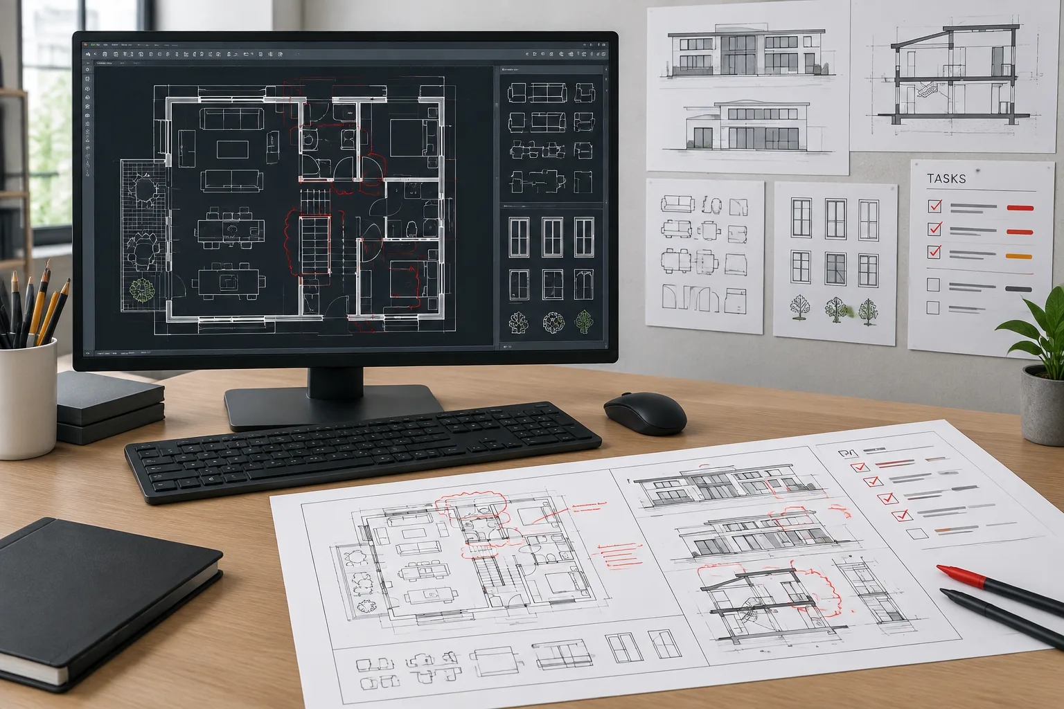
An architectural CAD redline workflow must do more than transfer comments from a markup into a drawing file. It must connect each requested change to the geometry, annotation, references, schedules, and related views that communicate the same design information.
The following workflow explains how to move from received markup to a verified drawing change while keeping questions, dependencies, and completion status visible. It is intended as a practical drafting and checking framework that can be adapted to a project team’s document-control procedures.
Redlines are more than instructions to move lines or replace notes. A single markup may affect plans, elevations, sections, schedules, details, and consultant backgrounds. If a drafter treats each redline as an isolated graphic edit, the visible correction may be made while related information remains outdated.
A dependable architectural CAD redline workflow separates interpretation, drafting, coordination, and verification. It also preserves the reviewer’s intent without turning the drawing file into an uncontrolled collection of revision clouds, temporary notes, and uncertain geometry.
What Counts as a Redline?
A redline is any reviewed markup that communicates a requested drawing change, correction, question, or coordination item. It may arrive as a marked PDF, printed sheet, sketch, screenshot, meeting note, or comment in a review platform.
Not every redline is immediately actionable. Markups commonly fall into several categories:
- Direct edits: Clear instructions to change a label, line, symbol, dimension, or object.
- Design decisions: Changes to layout, material, configuration, or appearance that may affect multiple views.
- Coordination items: Comments requiring comparison with structural, civil, MEP, landscape, interiors, or other information.
- Questions: Markups that identify uncertainty but do not yet provide an approved answer.
- Verification requests: Instructions to confirm an existing condition, product requirement, consultant location, or field measurement.
Classifying each markup before editing helps prevent assumptions from entering the drawings as if they were confirmed project information.
Establish a Controlled Markup Source
Before changing a DWG file, identify which markup set is current. Teams can lose substantial time when multiple PDFs with similar names circulate through email or project folders.
A controlled redline source should make the following information clear:
- The drawing issue or sheet set being reviewed
- The reviewer or review group
- The date or sequence of the markup
- Whether the markup is active, superseded, answered, or on hold
- Whether later comments modify earlier instructions
Keep the original markup unchanged. If responses or completion marks are added, save them in a working copy or use a process that preserves the original review record. This allows the drafter and checker to return to the reviewer’s actual instruction rather than relying on memory.
Review the Entire Set Before Starting
It is tempting to open the first sheet and begin drafting immediately. A better approach is to scan the complete markup set first. This reveals repeated comments, dependencies, and potential conflicts.
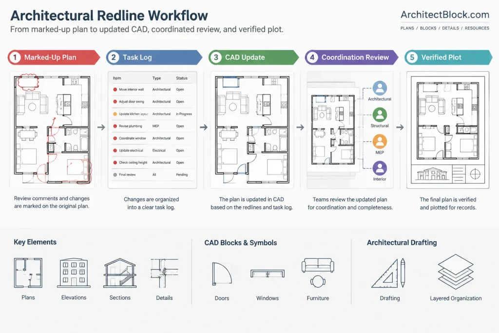
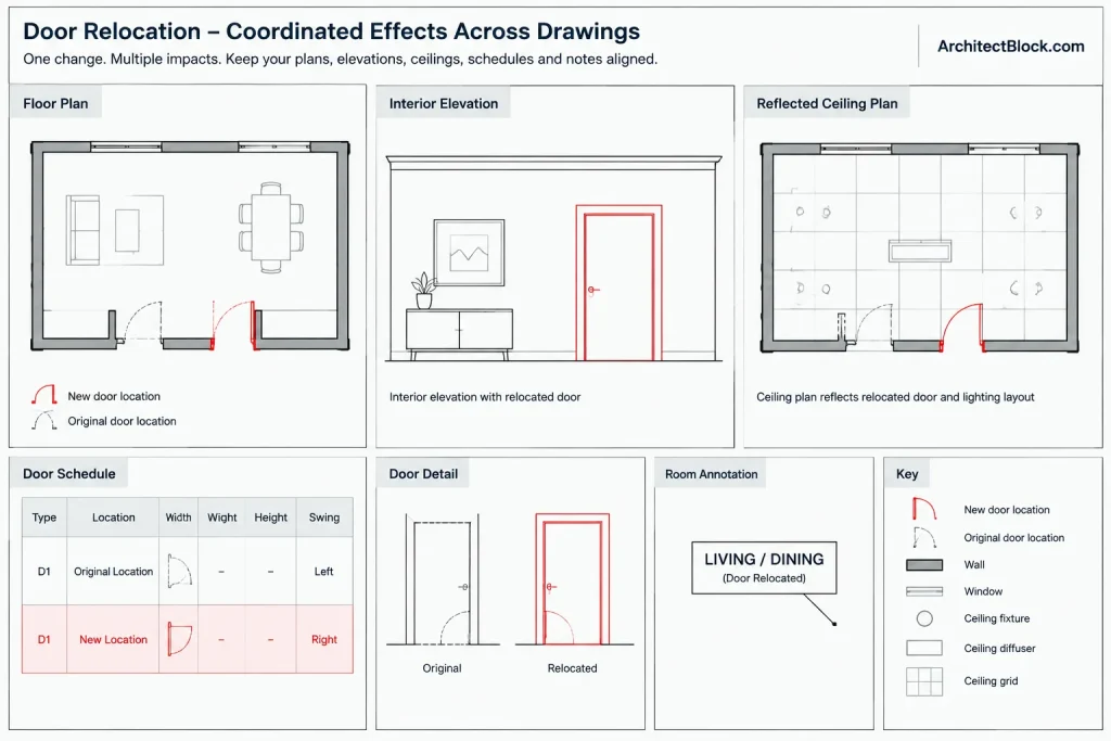
For example, moving a door on a floor plan may also affect an interior elevation, a room tag, a finish transition, a ceiling layout, a hardware reference, and a door schedule. Reading all related comments before editing helps determine whether the reviewer has already addressed those consequences elsewhere.
During this initial review, identify:
- Markups that affect more than one drawing
- Instructions that conflict with another comment
- Changes that require a design decision
- Items dependent on consultant or field information
- Comments that refer to missing or obsolete views
Convert Markups into Trackable Tasks
Complex redline sets are easier to manage when comments are converted into a simple task log. The log does not need to duplicate every word on the markup. Its purpose is to establish ownership, status, and coordination scope.
| Log field | Purpose |
|---|---|
| Markup reference | Connects the task to a sheet, view, or identifiable comment. |
| Requested action | Summarizes the intended change in drafting terms. |
| Affected drawings | Lists plans, elevations, sections, details, schedules, or backgrounds to check. |
| Status | Distinguishes pending, in progress, completed, questioned, and verified items. |
| Assigned person | Identifies who is responsible for the edit or decision. |
| Resolution note | Records how an unclear or coordinated issue was resolved. |
For a small set, this information may be tracked directly on a working PDF. Larger or multi-discipline reviews often benefit from a separate log so unresolved items do not disappear among completed comments.
Interpret Intent Before Editing Geometry
A markup sketch may indicate intent rather than exact geometry. A hand-drawn wall, fixture, or door location should not automatically be traced as though it were a measured layout.
Before making a change, ask what the markup is trying to accomplish. Is it correcting an error, creating clearance, aligning elements, responding to another discipline, or documenting a design decision? Then compare that intent with the current CAD base and related project information.
When a comment is ambiguous, flag it rather than inventing a solution. A concise question should identify the affected sheet, describe the uncertainty, and explain which related condition prevents a confident edit. It is generally more efficient to resolve uncertainty early than to revise several coordinated views twice.
Update the Authoritative Geometry First
When the same building element appears in multiple drawings, begin with the file or view that acts as the primary source for its location. In a conventional CAD workflow, that may be a referenced floor plan, an enlarged plan, a site base, or another designated background.
A practical edit sequence is:
- Confirm that the correct project file and current reference files are open.
- Locate the authoritative geometry for the marked element.
- Make the physical or spatial change.
- Update dependent annotations in the same drawing.
- Review related views and schedules.
- Regenerate or refresh sheets and plot a check set.
Avoid correcting only a sheet-specific copy when the same geometry is used elsewhere. Duplicate geometry can make one view appear correct while the source plan remains unchanged.
Separate Model Changes from Annotation Changes
Redlines often combine building changes and documentation changes. Keeping these categories mentally separate improves accuracy.
Model or design information
- Walls, openings, stairs, fixtures, equipment, and casework
- Room boundaries and circulation
- Exterior features and site elements
- Vertical relationships shown in elevations or sections
Annotation and sheet information
- Dimensions, tags, keynotes, and leaders
- View titles, references, and sheet notes
- Schedule entries and identifiers
- Graphic hierarchy, hatches, and linework display
Changing the annotation without changing the underlying design can create a misleading drawing. Conversely, changing geometry without reviewing its annotation can leave dimensions and tags pointing to obsolete conditions.
Run an Impact Check for Every Significant Change
An impact check is a deliberate search for other information affected by the redline. The exact scope depends on the element, but a useful review can include:
- Overall and enlarged plans
- Reflected ceiling and finish plans
- Exterior and interior elevations
- Building and wall sections
- Door, window, room, finish, or equipment schedules
- Detail references and callouts
- Dimensions, tags, keynotes, and legends
- Consultant backgrounds and shared reference files
Search by element identity and relationship, not only by matching words. A moved partition may affect a ceiling termination even when neither drawing contains a common note or tag.
Handle Conflicts and Unresolved Items Explicitly
Do not mark a redline complete if part of the instruction remains unresolved. Use a visible status that distinguishes a finished drafting task from a question awaiting direction.
When comments conflict, document the conflict and identify which decision is needed. Do not quietly choose one reviewer’s instruction unless project responsibility and direction are clear. If a temporary assumption is authorized, record it so the checker knows what must be confirmed later.
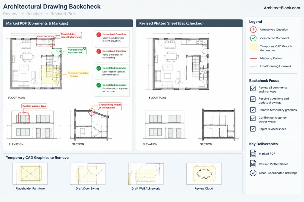
Redline clouds, colored text, temporary construction lines, and response notes should be kept out of issued drawing graphics unless they are intentionally part of the project’s revision presentation. Temporary aids should use controlled layers or another removable method so they can be reviewed and cleaned reliably.
Backcheck Against the Markup, Not Memory
After editing, compare the plotted or published drawing directly with the original redline. Reviewing only the CAD model is not enough because viewport display, references, annotation scale, layer visibility, clipping, and plotting can alter what appears on the final sheet.
For each markup, confirm:
- The requested change appears in the intended view.
- The old condition is fully removed where appropriate.
- Related dimensions, notes, tags, and references are current.
- No temporary graphics or drafting aids remain visible.
- The change is legible at the sheet’s plotted scale.
- Other affected drawings have been reviewed.
Mark the item complete only after this comparison. A checkmark based solely on having performed an edit does not confirm that the sheet communicates the result correctly.
Perform a Second-Person Check When Appropriate
Significant or coordinated redlines benefit from review by someone other than the original drafter. The checker should focus on intent and downstream effects, not merely whether a line moved.
A useful checking order is to review the redline, inspect the revised sheet, examine related views, and then consider whether the change introduced a new conflict. This method is especially helpful for changes involving circulation, exterior openings, vertical alignment, room configuration, or consultant interfaces.
Close the Redline Set Cleanly
At completion, the working markup should show which items were incorporated, which were answered another way, and which remain open. Avoid closing the set while unresolved questions are hidden among finished comments.
Archive the completed markup according to the project’s document-control process. Remove temporary CAD content, confirm that references are current, and create a final check plot before the drawings move into the next review or issue stage.
A disciplined architectural CAD redline workflow turns markups into coordinated drawing changes rather than isolated corrections. The essential habits are simple: control the source, understand intent, edit authoritative information, check every affected view, and verify the plotted result. Those steps reduce repeated work and make the drawing set more dependable for everyone who uses it.
Define What Complete Means Before Closing a Markup
A redline can appear resolved in CAD while remaining incomplete in the drawing set. A useful definition of completion includes the requested edit, the removal of obsolete information, coordination of dependent content, and confirmation that the published sheet displays the intended result.
Completion criteria should match the scope of the comment. A note correction may require a focused annotation check, while a change to a building element may require review across plans, elevations, sections, schedules, details, and consultant references. This prevents every markup from receiving the same superficial check regardless of its impact.
Create a Clear Verification Trail
The drafter, checker, and reviewer should be able to understand what changed and how an unclear item was resolved. The record can be simple, but it should distinguish completed work from assumptions, questions, and items awaiting outside information.
- Requested: State the reviewer’s intended outcome without adding an unsupported interpretation.
- Changed: Identify the drawing information that was actually revised.
- Coordinated: Note which related views, schedules, annotations, or references were checked.
- Resolved: Record the direction received for questions or conflicting comments.
- Verified: Confirm that the plotted or published output was compared with the controlled markup.
This verification trail is especially useful when work passes between team members. It reduces the need to reconstruct decisions from file dates, temporary CAD graphics, or memory.
Use the Final Sheet as the Communication Test
The CAD file is the editing environment, but the drawing sheet is usually the communication product. A technically correct edit can still fail if it is hidden by a viewport, obscured by other graphics, disconnected from a leader, or excluded by layer visibility.
Final review should therefore ask whether a person reading the sheet can understand the revised condition without access to the working markup. If the change depends on temporary notes or reviewer knowledge, the permanent drawing information may still be incomplete.
Architectural CAD Redline Workflow FAQ
Should a drafter trace the geometry shown in a hand-drawn markup?
Not automatically. A sketch may communicate direction, approximate location, or design intent rather than exact geometry. The drafter should compare it with the authoritative CAD information and request clarification when the intended position or relationship is uncertain.
What should happen when a redline conflicts with a consultant background?
The conflict should be documented and directed to the responsible project team members. The item should remain visibly unresolved until appropriate direction is received. Quietly selecting one condition can conceal a coordination issue.
Is an annotation-only redline limited to text editing?
Not necessarily. Before changing a note, tag, dimension, or schedule entry, confirm that the underlying design information already matches the requested condition. An annotation edit should not be used to disguise geometry that remains incorrect.
How can a team tell whether a redline is fully complete?
Compare the current plotted or published sheet with the controlled markup. Confirm that the intended change is visible, obsolete information is removed, dependent content has been reviewed, temporary drafting aids are absent, and unresolved questions remain clearly identified.
Does every redline require a separate checker?
The appropriate review level depends on the project’s procedures and the effect of the change. Items with broader coordination consequences benefit from an independent check because the original drafter may naturally focus on the edit performed rather than every downstream effect.
Is a completed markup the same as a formal revision record?
Not necessarily. A working markup documents review and drafting activity, while formal revision records follow the project’s issue and document-control process. Teams should preserve redline records without treating them as a substitute for required issue documentation.