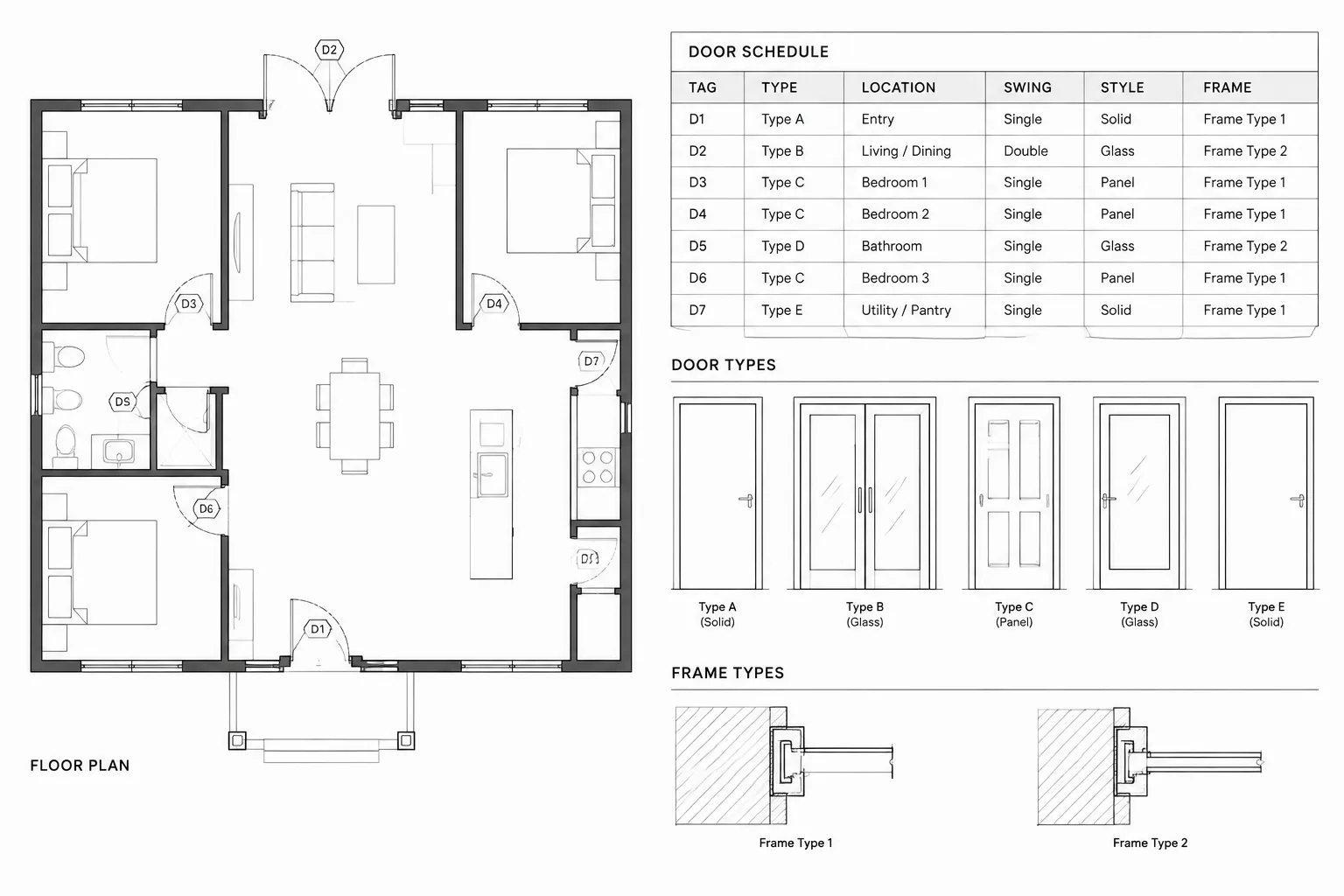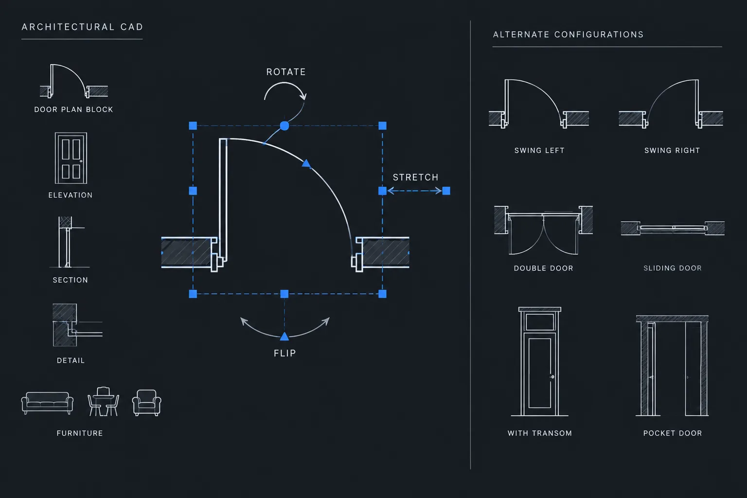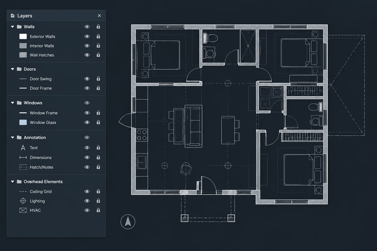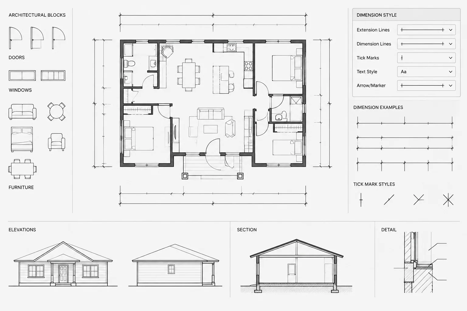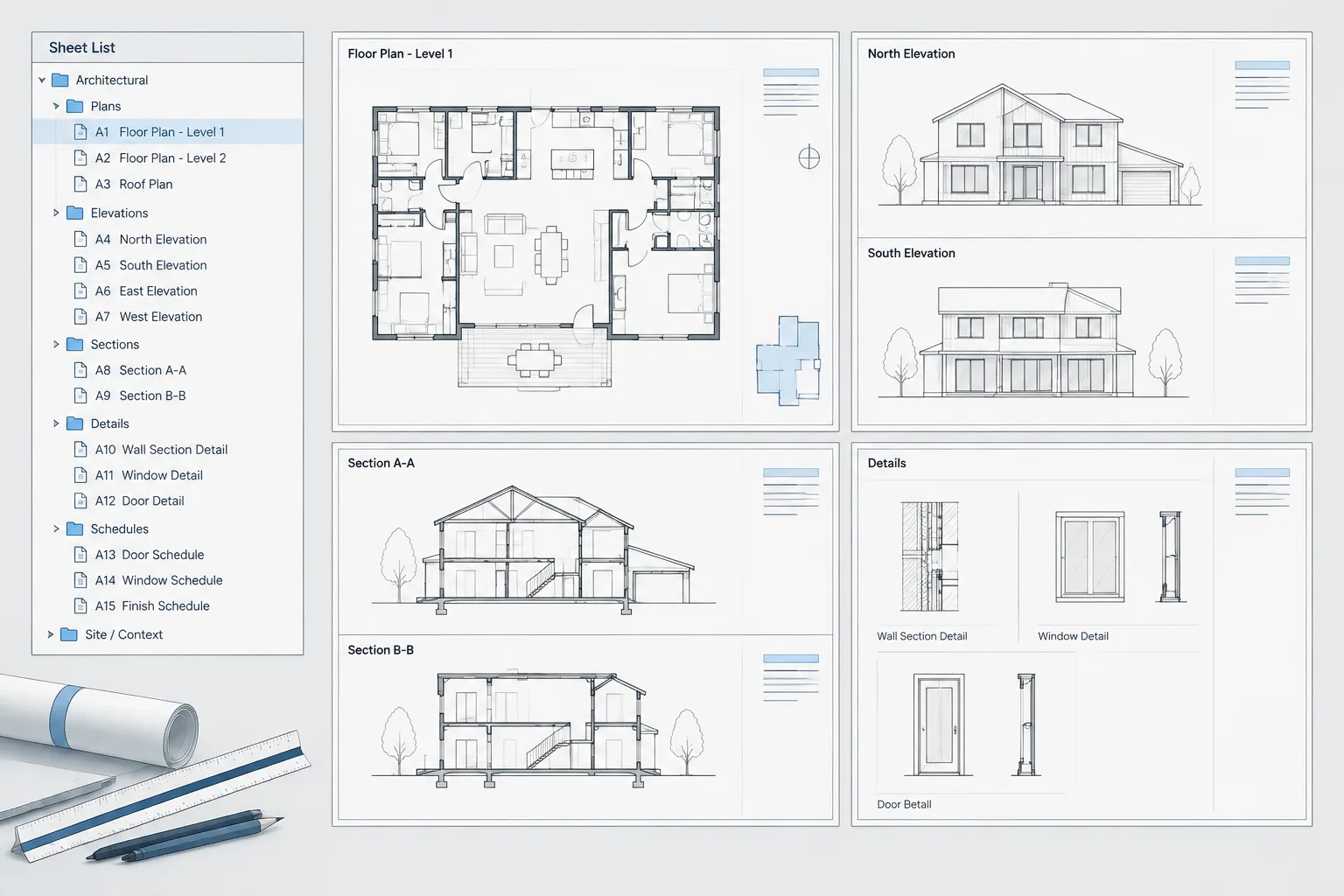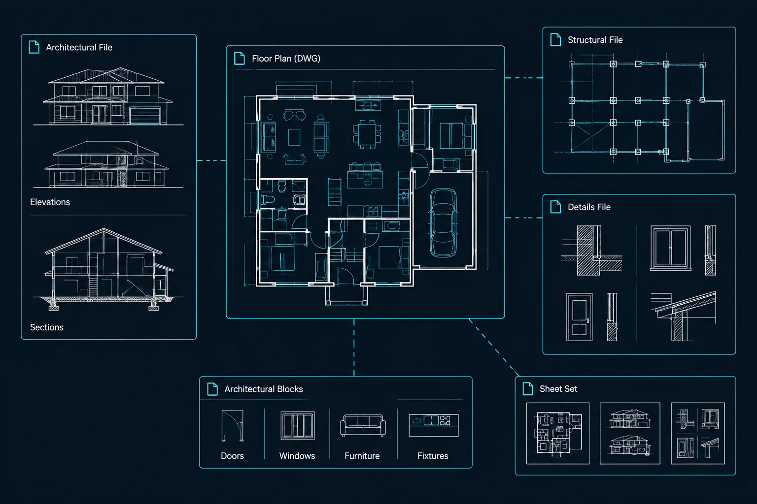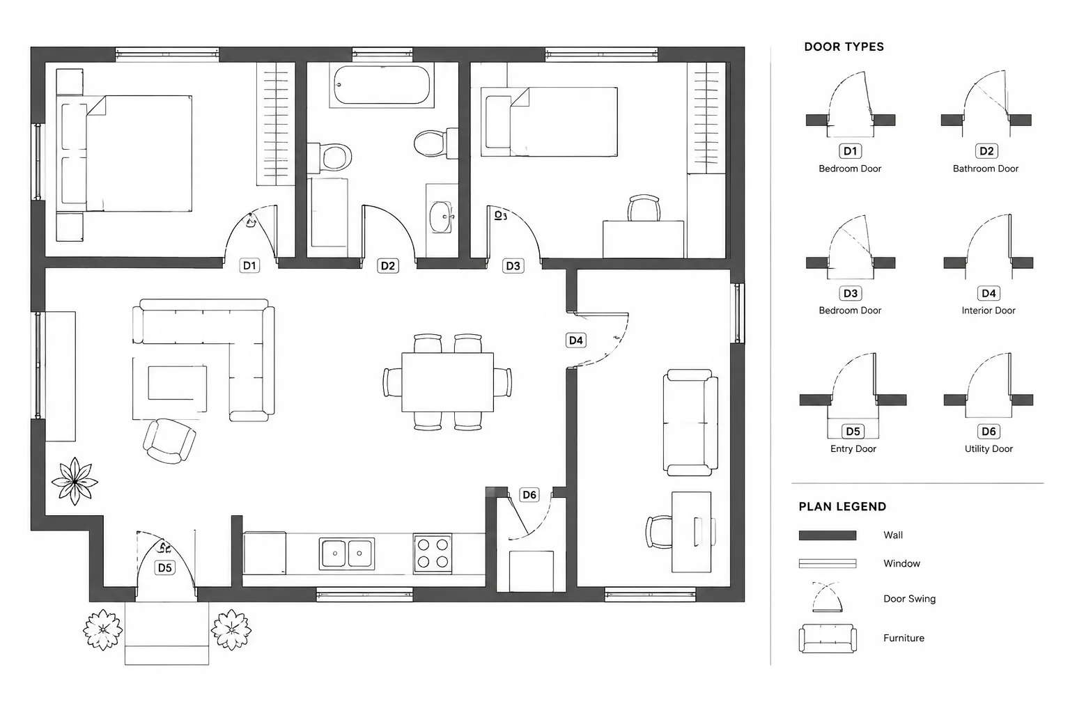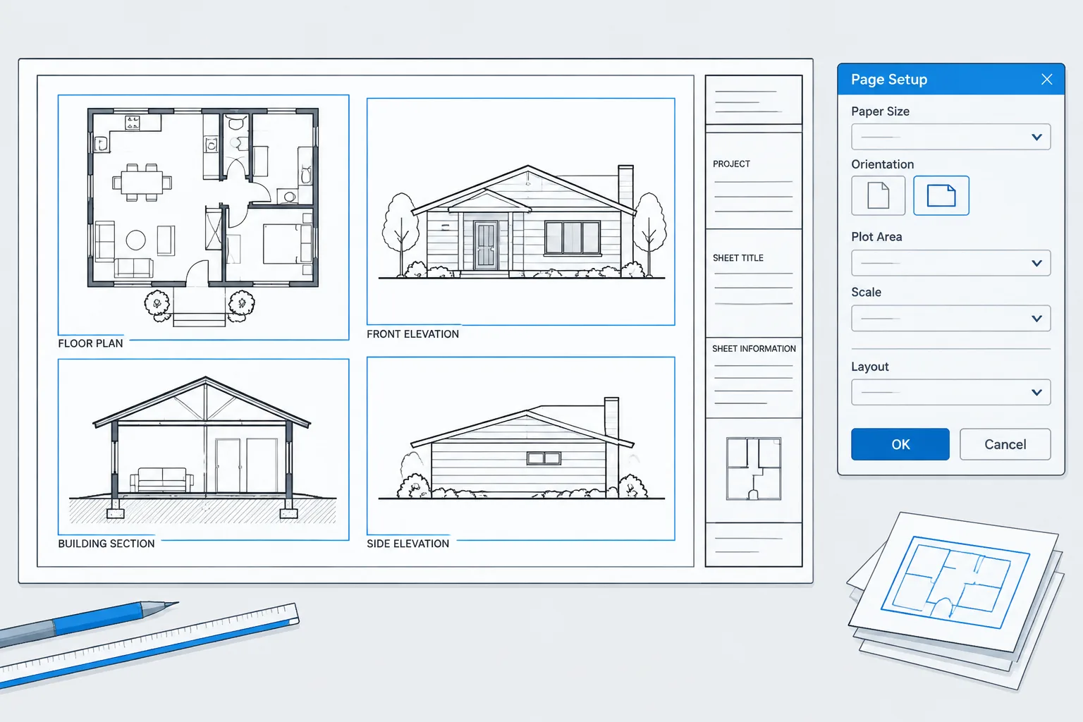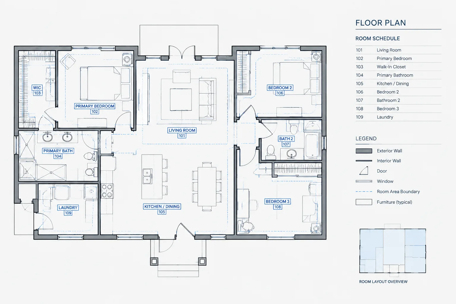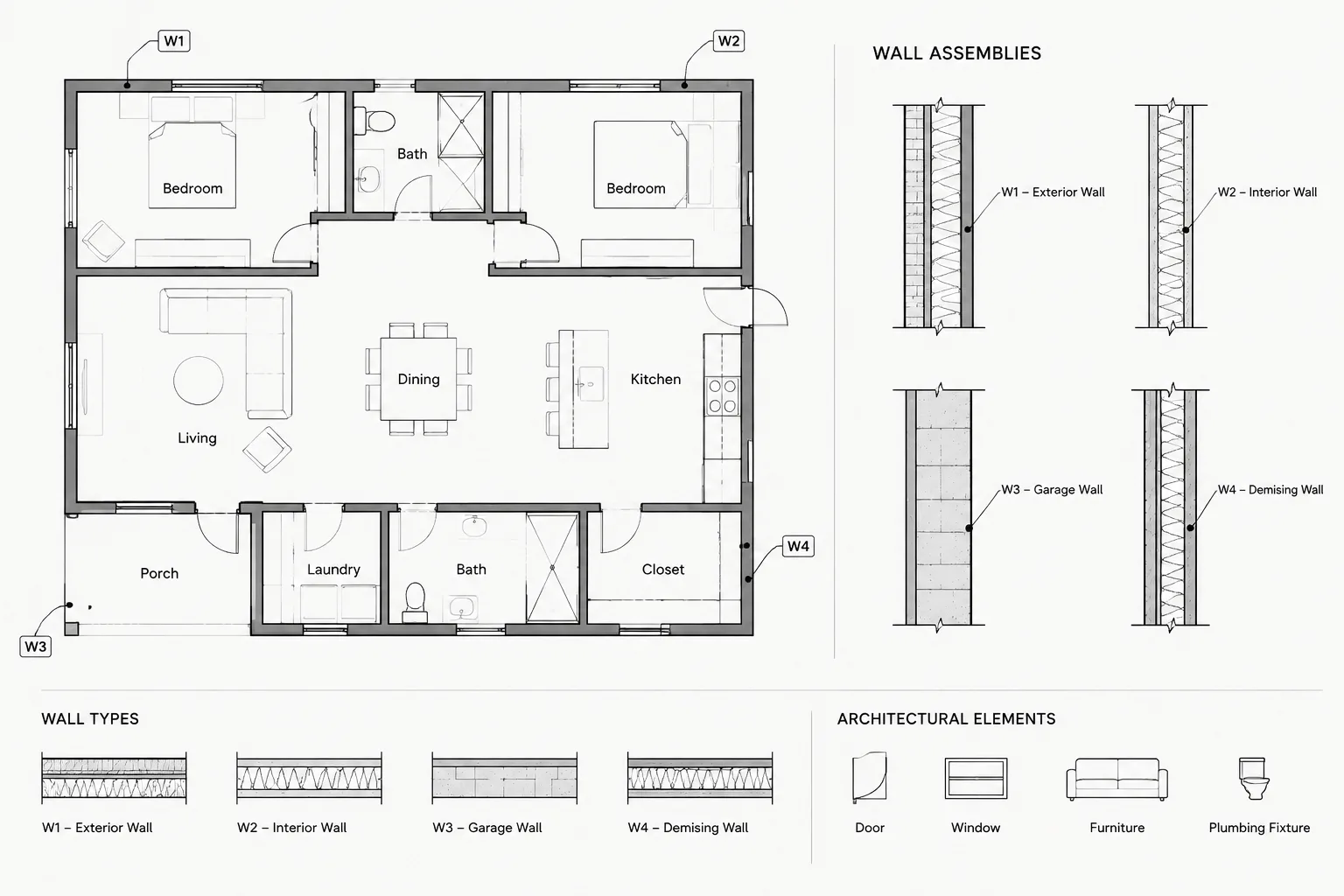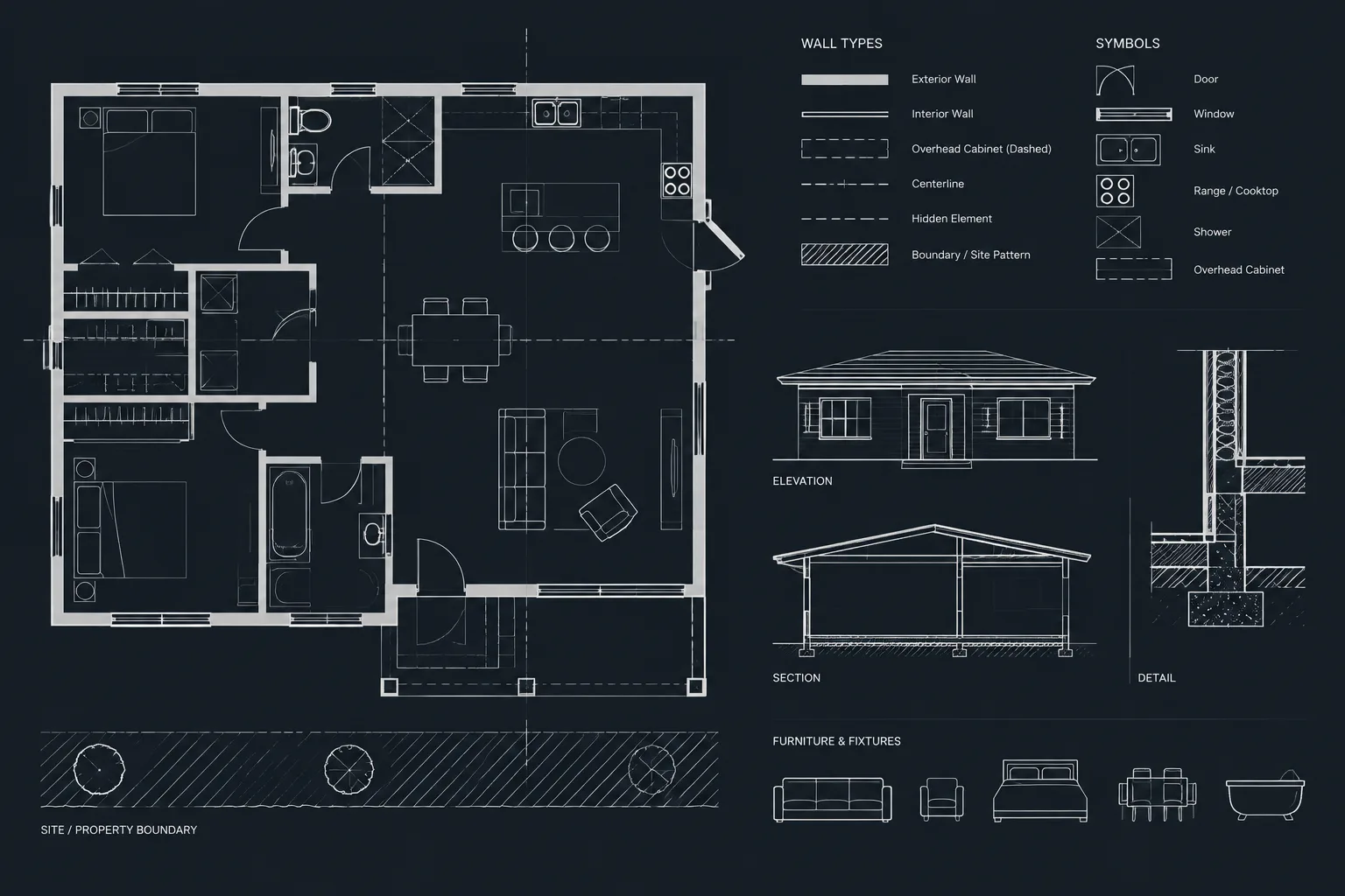
Architectural CAD linetypes are most effective when their meaning, layer assignment, display scale, and plotted appearance are coordinated. A line that looks correct in the drawing editor can still become unclear in a viewport or published sheet.
This practical guide covers a disciplined setup and troubleshooting process for dashed, hidden, center, overhead, and boundary patterns. Use it to trace problems from individual object properties through layers, viewports, referenced content, and final output.
Linetypes help an architectural drawing communicate conditions that cannot be shown clearly with continuous lines alone. Dashed, centered, hidden, overhead, and boundary patterns can distinguish projected objects, concealed construction, reference geometry, and site information. When they are managed poorly, however, dashed lines may appear continuous, patterns may change from one viewport to another, and plotted sheets may not match the drawing editor.
A reliable linetype workflow is not simply a matter of loading a dashed pattern and assigning it to objects. The result depends on layer properties, object overrides, drawing units, global settings, object-level scale, viewport behavior, and the final plotting scale. This guide explains how those pieces work together and provides a practical method for diagnosing inconsistent architectural CAD linetypes.
What a linetype should communicate
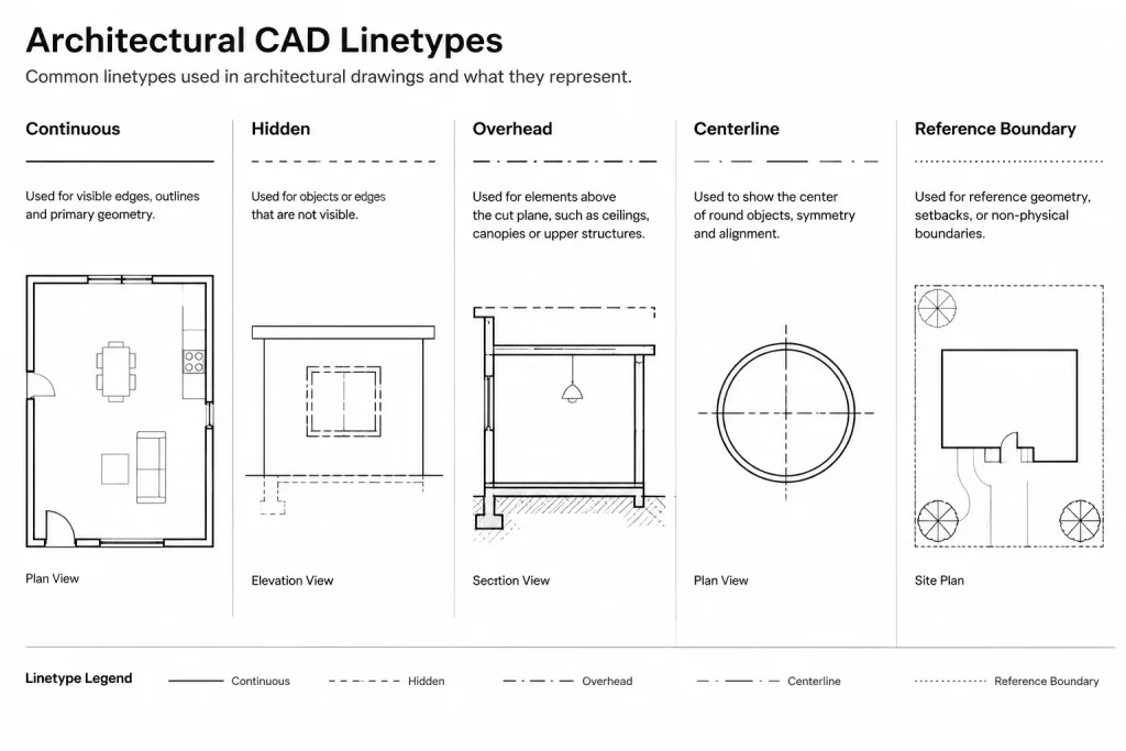
Each linetype should have a defined graphical purpose. The same dashed pattern should not represent an overhead cabinet in one view, demolished construction in another, and a property boundary elsewhere unless the drawing context makes those meanings unmistakable.
Common architectural uses include:
- Overhead elements: cabinets, shelving, beams, soffit edges, roof overhangs, or other objects above the plan cut plane.
- Hidden construction: features concealed by another material or surface when showing them is necessary for coordination.
- Centerlines: axes through openings, equipment, circular elements, or symmetrical assemblies.
- Reference limits: setbacks, easements, work limits, clearance zones, and other nonphysical boundaries.
- Movement or operation: selected door, equipment, partition, or furniture movement paths when these are part of the drawing convention.
- Existing, removed, or future work: graphic distinctions used in alteration drawings, subject to the project’s established legend and layer system.
Linetype alone should not carry every meaning. Layer names, lineweights, notes, symbols, hatches, and legends may also be needed. This is especially important when drawings are printed in grayscale or reduced in size.
Start with layers rather than individual objects
For most architectural geometry, assign the linetype to a layer and keep objects set to ByLayer. This creates one controlled location for changing the appearance of related objects. For example, all overhead casework lines can share a dedicated layer with a suitable linetype and lineweight.
Direct object overrides may be justified for a limited exception, but frequent overrides make files difficult to audit. Two visually identical lines may behave differently because one inherits its properties from the layer while the other contains an object-level linetype or scale override.
A practical assignment sequence
- Identify what the line represents.
- Place it on the correct architectural layer.
- Set the object’s color, linetype, and lineweight to ByLayer unless a documented exception is required.
- Confirm that the intended linetype definition is loaded in the drawing.
- Review the result at the sheet viewport scale, not only while zoomed closely in model space.
Understand the different scaling controls
A linetype is a repeating pattern made from dashes, gaps, dots, or embedded elements. Its apparent size is affected by several controls. Troubleshooting is easier when these controls are treated separately.
| Control | What it affects | Typical coordination concern |
|---|---|---|
| Drawing linetype definition | The underlying dash-and-gap pattern | Different source files may contain patterns intended for different unit conventions. |
| Global linetype scale | The general pattern scale throughout the drawing | A broad change can alter every dashed line, including lines that were already correct. |
| Object linetype scale | The pattern scale applied to an individual object | Copied objects may carry unexpected overrides. |
| Current object scale setting | The scale assigned to subsequently created objects | New geometry may differ from existing geometry without an obvious visual reason. |
| Model-space display behavior | How patterns respond to annotation scale in the model tab | The model view may not resemble the intended sheet presentation. |
| Paper-space viewport behavior | How patterns display through viewports with different scales | The same line may appear with different dash lengths on separate sheets. |
Avoid using the global scale as the first fix for one incorrect line. Check the object’s properties and source first. If the issue affects every dashed line, a drawing-level setting becomes a more likely cause.
Model space and paper space can show different results
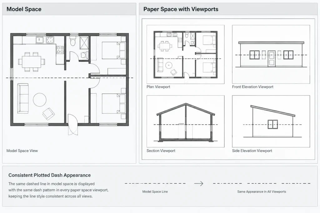
Architectural drawings are often created at full size in model space and presented through scaled paper-space viewports. Linetype display settings can compensate for viewport scale so that dash patterns have a consistent plotted appearance across differently scaled views.
This is useful when a floor plan, enlarged plan, and site view must share a coherent graphic language. Without coordinated viewport behavior, a dashed line may look balanced in one view but overly dense or nearly continuous in another.
After changing viewport-related linetype settings, regenerate the drawing and inspect the layout. A stale display can make a corrected setting appear ineffective. Always evaluate the resulting PDF or plotted output as well, because the editor preview is not the final deliverable.
A repeatable setup workflow
1. Establish project conventions
Define which conditions use dashed, hidden, center, or custom patterns. Record those conventions in the CAD template, project drafting guide, or drawing legend as appropriate. The goal is consistency rather than maximizing the number of available patterns.
2. Load only the patterns the project needs
An overloaded linetype list makes selection harder and can preserve duplicate or confusing definitions imported from outside files. Keep a controlled set of patterns suited to the project’s unit system and graphic requirements.
3. Assign patterns through layers
Create or use layers based on drawing meaning, not appearance alone. A layer named only for a dashed appearance says less than a layer associated with overhead casework, hidden structure, or a site boundary. Semantic layer organization makes visibility control and quality review more reliable.
4. Test at actual sheet conditions
Create representative viewports using the scales expected in the set. Review short lines, long lines, arcs, polylines, and closed boundaries. A pattern that reads well on a long property line may not be suitable for a short overhead edge.
5. Verify continuity where necessary
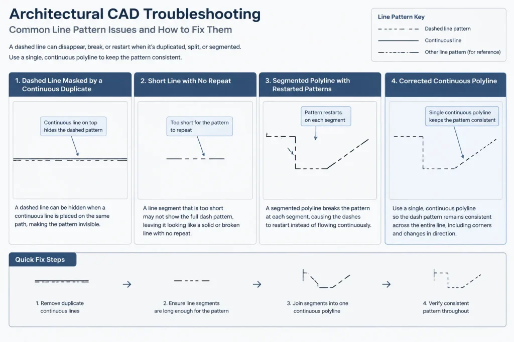
Segmented geometry can restart a linetype pattern at every segment, producing uneven dashes around corners. Where a continuous graphic rhythm matters, review whether the geometry should be joined into a polyline and whether its linetype generation behavior is appropriate. Do not join unrelated objects merely to improve appearance.
6. Plot a controlled test
Publish a sample sheet using the project page setup and plot style. Check whether thin dashed lines remain legible, whether gaps close up, and whether lineweights overpower the pattern. Screen appearance alone is not a sufficient quality check.
Why dashed lines sometimes appear continuous
This is one of the most common linetype problems. Work through the following checks instead of repeatedly changing random scales:
- Zoom and regenerate: The display may not have refreshed after a setting change.
- Check line length: A very short object may not be long enough to display a recognizable repeat.
- Inspect the object scale: An imported or copied object may contain an extreme linetype-scale override.
- Confirm the assigned linetype: The layer may be dashed while the object is explicitly set to Continuous, or the reverse.
- Review drawing units: Geometry copied between drawings with different unit assumptions may bring unsuitable pattern behavior.
- Inspect viewport settings: The model-space result may be correct while the paper-space presentation is not.
- Check overlapping geometry: A continuous duplicate line may be covering a dashed line in the same location.
Imported blocks and external references
Blocks and external references can introduce additional complexity. Block geometry may use explicit properties, internal layers, or ByBlock behavior instead of inheriting the host layer’s linetype. Editing only the block reference layer may therefore produce no visible change.
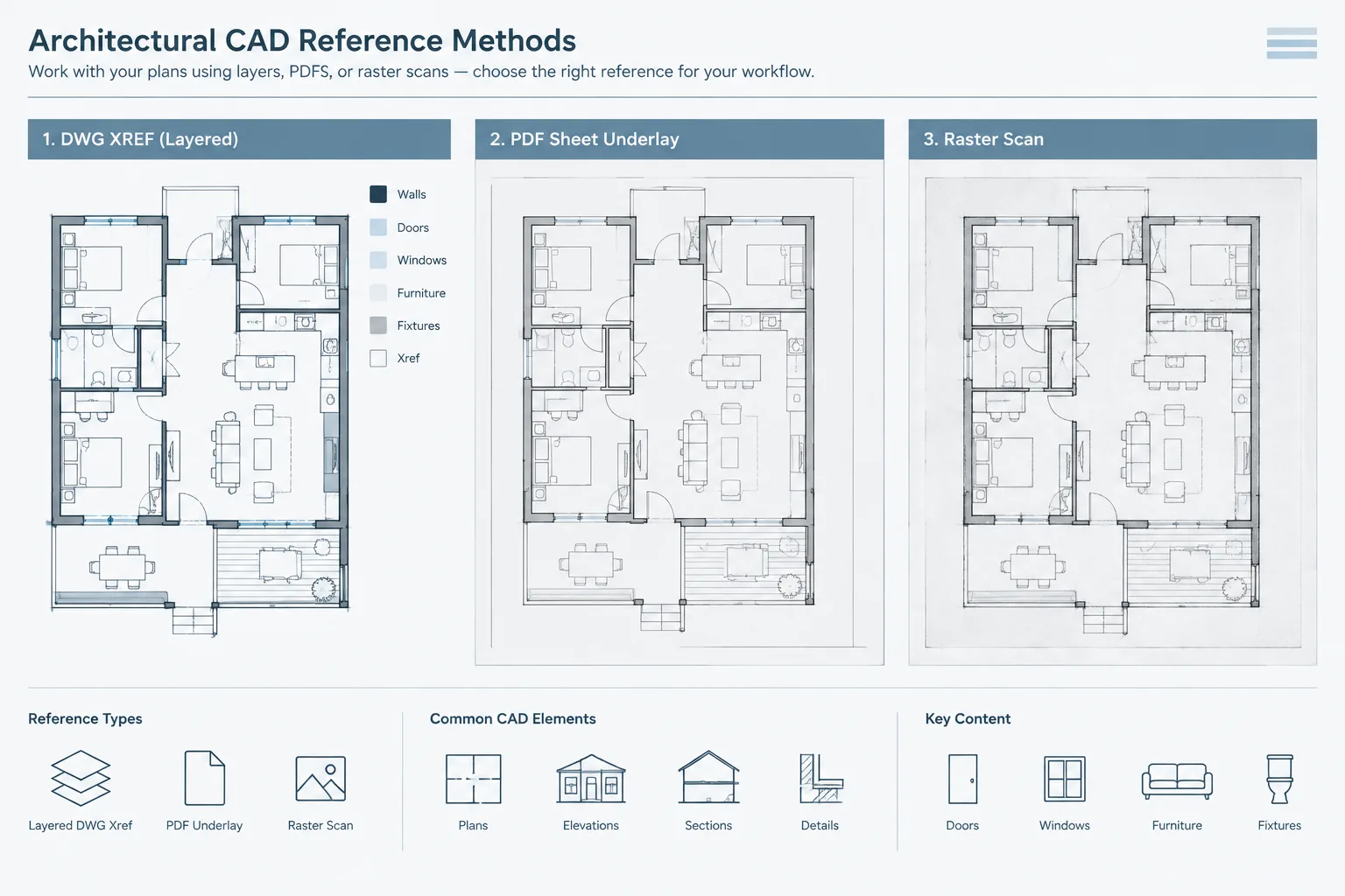
External references retain their own layer structure and drawing settings, although the host file can apply selected layer overrides for presentation. If an xref linetype is incorrect, determine whether the problem belongs in the source drawing or is specific to one host sheet. Fix source information at the source whenever possible; use host overrides only for intentional view-specific graphics.
When copying content from consultant or manufacturer files, avoid importing it directly into the production model without review. Clean the content in a controlled file, verify its units and properties, and convert unnecessary object overrides to the project’s layer conventions.
Quality-control checklist
- Every noncontinuous linetype has a clear drawing meaning.
- Objects use ByLayer properties unless an exception is intentional.
- Loaded linetypes suit the drawing’s unit convention.
- Model-space and viewport scaling settings follow the project template.
- Short segments and curved objects display clearly at plotted scale.
- Polyline patterns do not restart awkwardly at every vertex.
- Blocks and xrefs have been checked for internal overrides.
- Duplicate continuous lines are not masking dashed geometry.
- The published PDF matches the intended sheet appearance.
- Legends and notes agree with the graphical conventions actually used.
Keep the system predictable
The best architectural CAD linetype system is not the most elaborate one. It is the system in which each pattern has a stable purpose, objects inherit controlled layer properties, viewports present patterns consistently, and plotted sheets remain readable. Establish the settings in the project template, test them under real sheet conditions, and troubleshoot from the object level outward before changing global controls.
A symptom-based troubleshooting sequence
When a pattern looks wrong, begin with the smallest possible scope. This helps prevent a local object problem from turning into a drawing-wide graphics problem.
If only one object looks wrong
- Confirm that the object is on the intended layer.
- Compare its linetype and linetype-scale properties with nearby objects that display correctly.
- Look for an explicit property override rather than assuming the layer definition is at fault.
- Check whether the object is too short to show a recognizable portion of the pattern.
If an entire layer looks wrong
- Review the layer linetype and confirm that the expected definition is loaded.
- Check whether objects on the layer are actually set to ByLayer.
- Compare the affected layer with a known working layer under the same viewport and plotting conditions.
- Inspect whether overlapping geometry is obscuring the intended pattern.
If several drawings or viewports look wrong
- Review the project-wide linetype and viewport display settings.
- Confirm that imported geometry and referenced drawings follow compatible unit assumptions.
- Regenerate the affected views before judging whether a setting change worked.
- Compare the layout preview with the published output rather than relying on model-space appearance alone.
Document intentional exceptions
Some drawings require an object-level or viewport-specific exception, but the reason should be understandable to the next person who edits the file. Where possible, record special graphic treatment in the project drafting guide, layer notes, or quality-control process. Undocumented overrides are difficult to distinguish from accidental properties.
Review meaning as well as appearance
A technically correct dashed pattern can still be misleading if its purpose is unclear. During drawing review, verify that similar conditions use similar graphics and that different conditions remain distinguishable after plotting, reduction, or grayscale reproduction. The final test is not merely whether the dashes are visible, but whether they communicate the intended architectural condition without ambiguity.
Frequently asked questions
Why does a dashed linetype appear continuous?
The object may be too short to show the repeat clearly, its object-level scale may be unsuitable, the display may need regeneration, or a continuous duplicate may overlap it. Viewport behavior and drawing-unit assumptions can also affect the result.
Should linetypes be assigned to layers or individual objects?
Layer assignment with objects set to ByLayer is generally the clearest workflow for architectural drawings. Object overrides are better reserved for limited, documented exceptions.
Why does the same linetype look different in separate viewports?
The viewports may use different presentation scales or may not share coordinated linetype display behavior. Review the layout settings and evaluate the published sheet before changing the underlying pattern.
Why does changing the block layer not change its internal linetypes?
Objects inside the block may use explicit properties, internal layers, or ByBlock behavior. The block definition and its internal geometry must be inspected to identify where the appearance is controlled.
Should a global linetype scale be changed to fix one line?
Not as the first response. Inspect the affected object, its layer, and any local override before changing a setting that can alter dashed patterns throughout the drawing.
How should linetype problems in an external reference be handled?
Determine whether the problem belongs to the referenced source drawing or only to its presentation in the host file. Correct source information in the source when possible, and reserve host overrides for intentional sheet-specific graphics.
Why do dashes restart at polyline corners?
Pattern behavior can depend on whether geometry consists of separate segments and how linetype generation is handled. Review whether the elements should form a continuous polyline, while avoiding the joining of unrelated objects solely for graphic appearance.