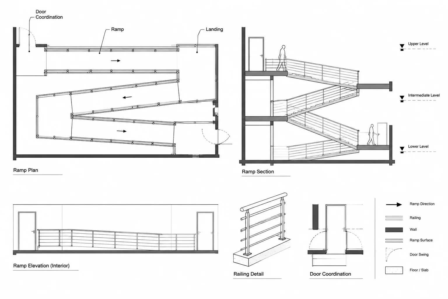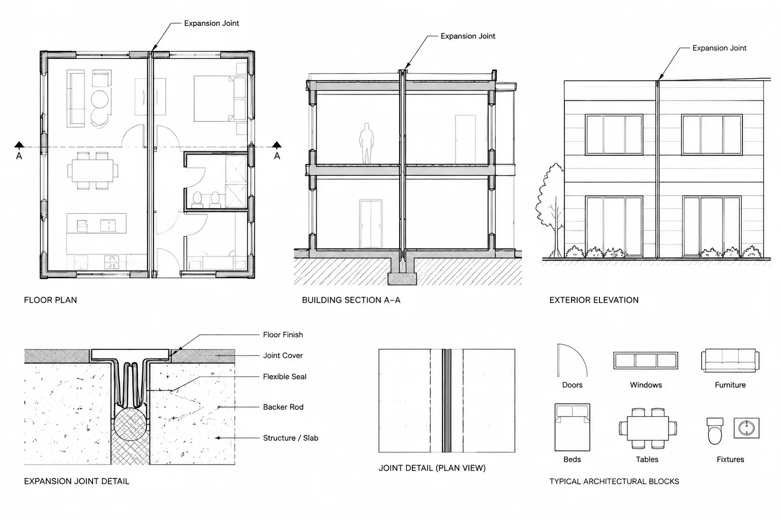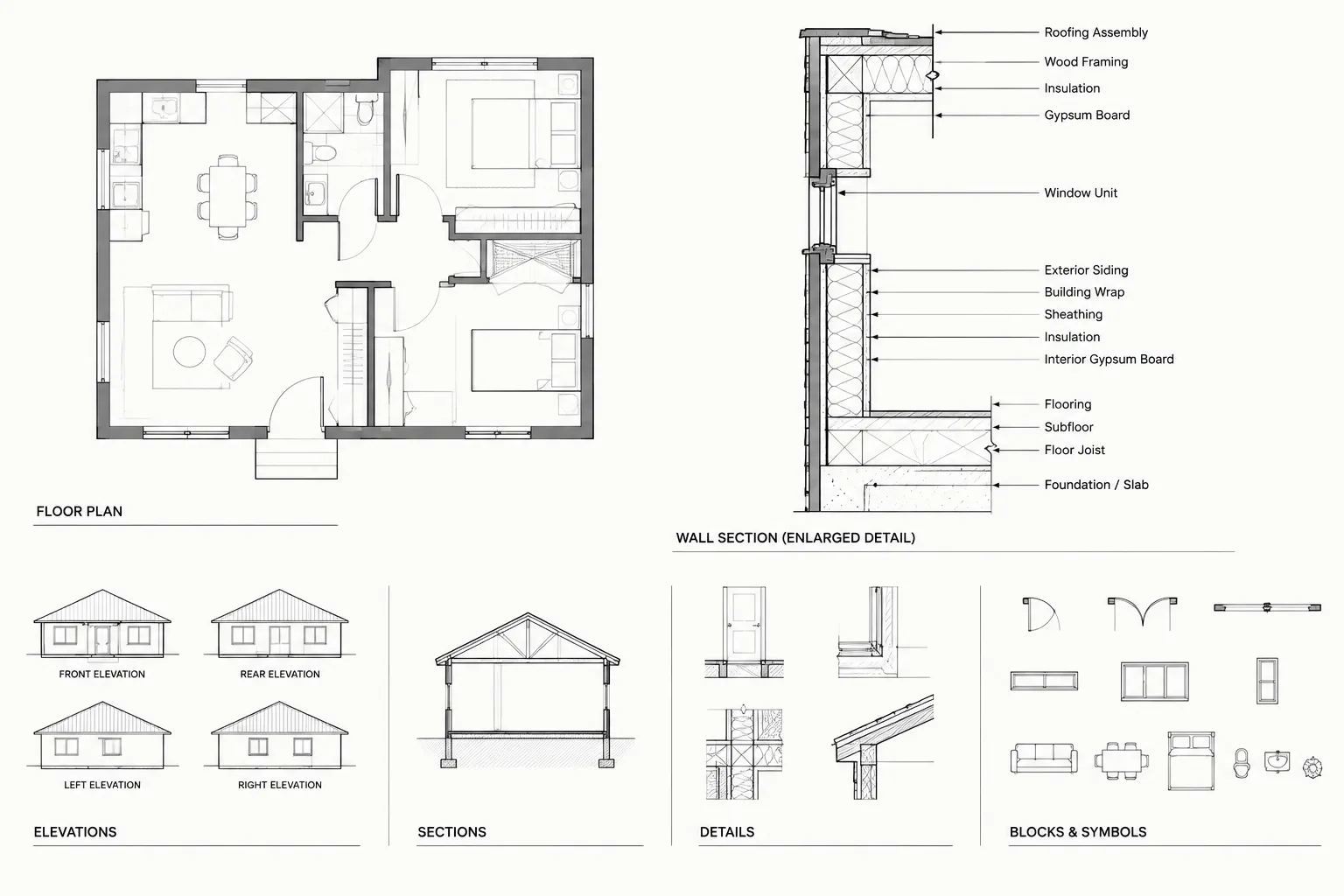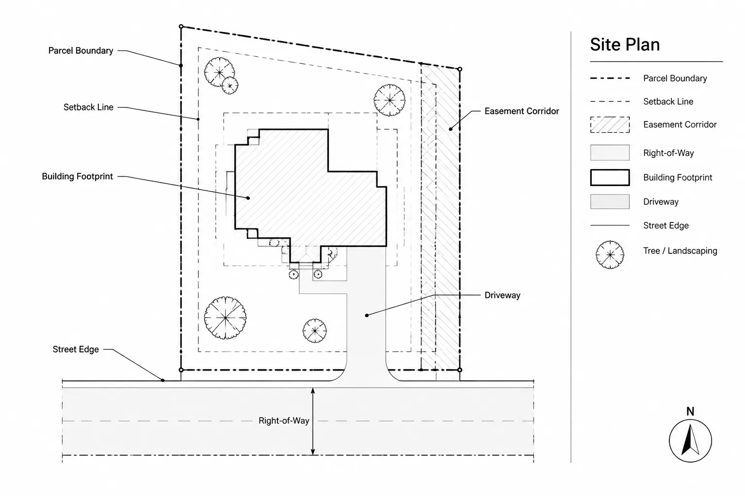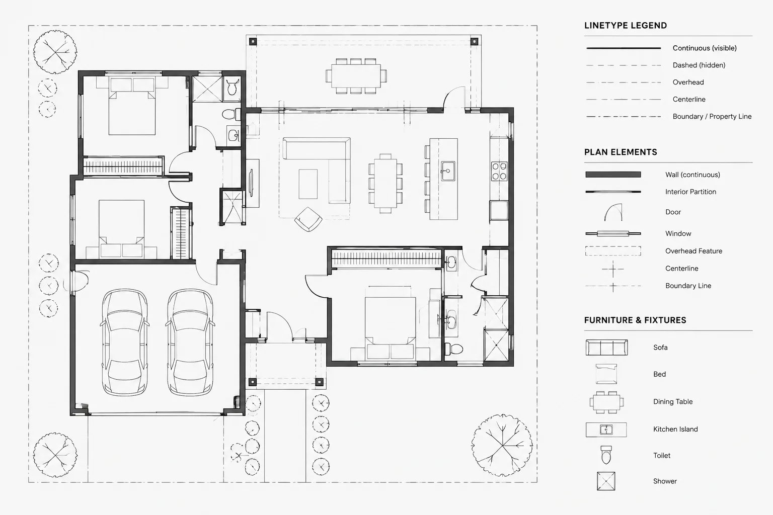
Architectural CAD linetypes form part of a drawing’s visual language. A continuous, dashed, center, boundary, or movement pattern should tell the reader something specific about an element’s position, status, or function. That meaning must remain understandable when the drawing is viewed in a layout, plotted in monochrome, reduced for review, or coordinated with consultant files.
This guide explains how to organize architectural CAD linetypes through layers, distinguish them from lineweights, manage their appearance across viewports, and troubleshoot patterns that do not display as intended. Use the principles alongside the graphic standards, plotting workflow, and documentation requirements established for the project.
Architectural CAD linetypes communicate more than object appearance. They help readers distinguish visible edges from concealed construction, overhead elements, centerlines, boundaries, movement paths, and other information that cannot be explained by lineweight alone. When linetypes are inconsistent or poorly scaled, a technically complete drawing can become difficult to interpret.
A reliable linetype workflow begins with meaning, not decoration. Each pattern should have a defined purpose, remain readable at the drawing’s plotted scale, and work with the project’s layers, lineweights, viewports, and annotation. The exact conventions may vary by office, client, consultant, or project, so downloaded templates and DWG files should always be checked before use.
What a Linetype Communicates
A linetype is the repeating visual pattern assigned to a CAD object or layer. It may be continuous, dashed, dotted, patterned, or combined with text or symbols. In architectural drawings, this pattern usually identifies the status, position, or function of an element.
Linetype and lineweight perform different jobs:
- Linetype identifies a graphic category, such as hidden, overhead, centered, or beyond.
- Lineweight establishes visual emphasis and depth, such as a cut element versus a surface seen in elevation.
- Color may support layer management or plotting, but it should not be the only way information is distinguished.
For example, two lines may use the same dashed pattern but require different plotted weights because one represents an overhead cabinet and the other represents a distant building edge. The pattern explains the condition; the weight helps establish hierarchy.
Common Architectural Uses
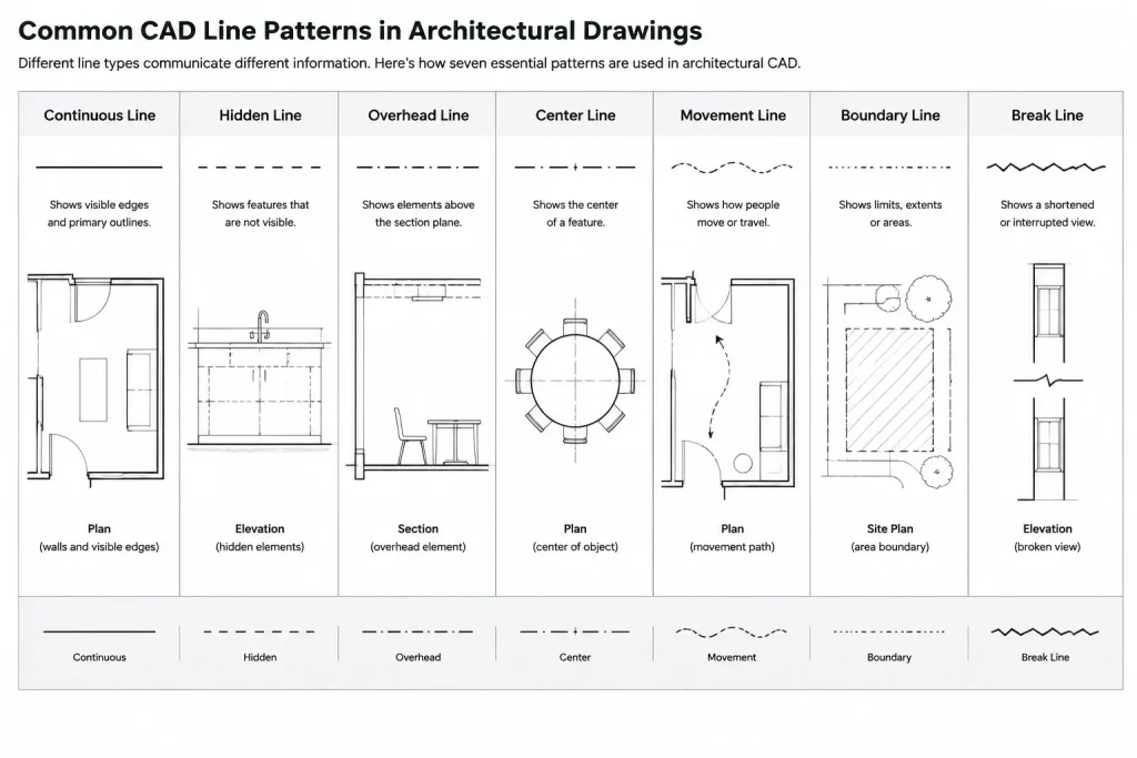
| Linetype category | Typical use | Coordination concern |
|---|---|---|
| Continuous | Visible edges, wall faces, fixtures, casework, and annotation leaders | Use lineweight to separate cut, profile, surface, and fine-detail information |
| Hidden or dashed | Concealed construction, objects behind a surface, or elements outside the direct view | Do not use one generic hidden pattern for unrelated conditions without a clear legend |
| Overhead | Cabinets, projections, roof edges, beams, openings, or equipment above the plan cut | Coordinate with reflected ceiling plans, sections, and floor plan cut-plane conventions |
| Centerline | Opening centers, circular elements, structural grids, equipment axes, or alignment references | Grid lines and major control lines may need their own layer and graphic hierarchy |
| Phantom or movement pattern | Alternate positions, door movement, operable panels, or movable equipment extents | Confirm that the pattern cannot be mistaken for demolition or hidden work |
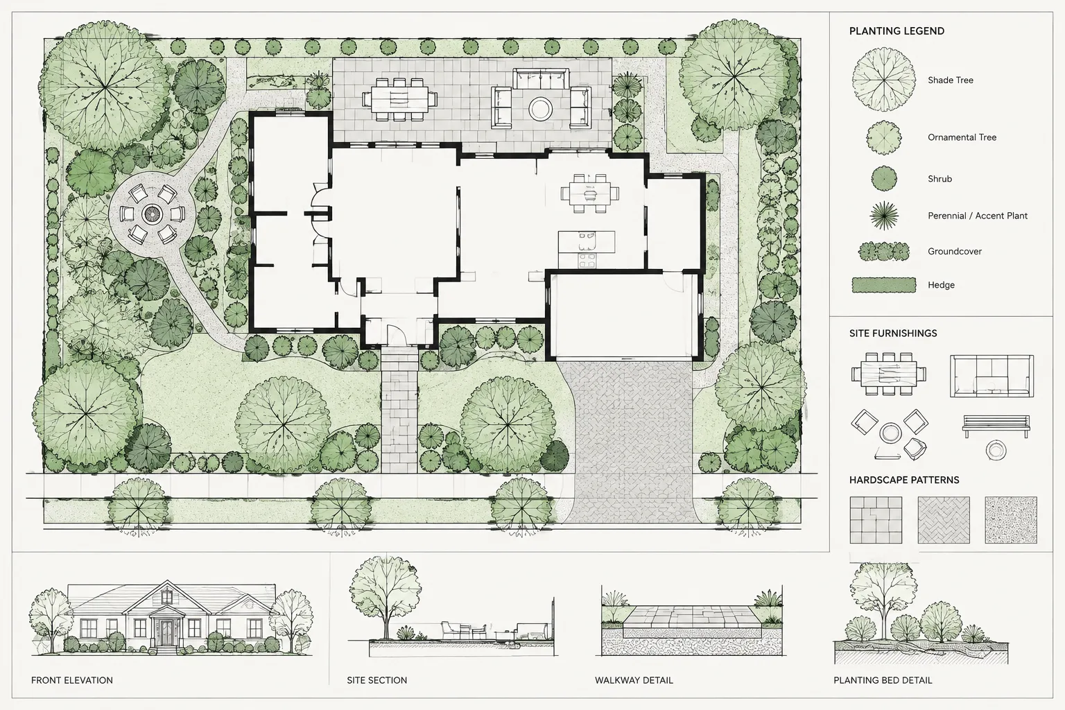
| Boundary pattern | Property limits, work limits, easements, zones, or other defined extents | Use terminology and symbols consistent with the survey and project documents |
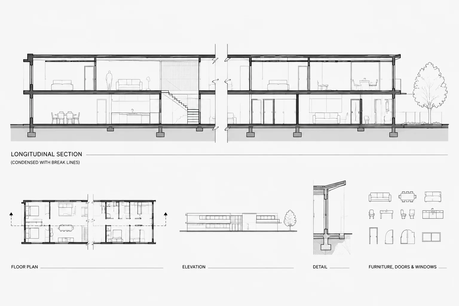
| Break line | Interrupted views, shortened assemblies, or partial detail limits | A break should not obscure dimensions or imply that critical information is omitted |
These are common applications rather than universal rules. A consultant background may use the same dash pattern for a different purpose, making layer names and drawing legends especially important during coordination.
Build Linetype Meaning into the Layer System
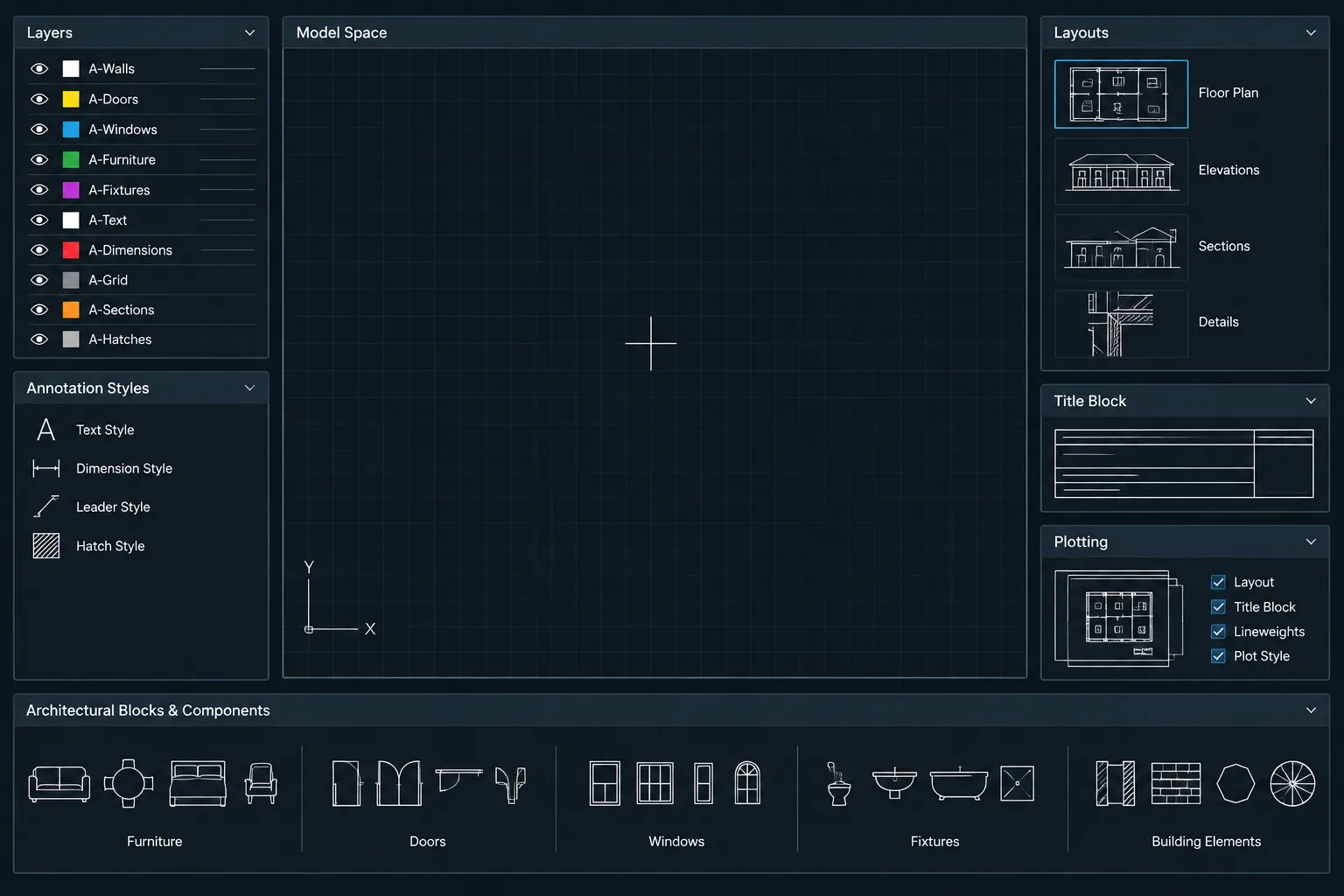
For most architectural drafting, assign linetypes by layer rather than directly to individual objects. Objects can then remain set to inherit their properties from the layer, allowing the drawing team to change a category consistently.
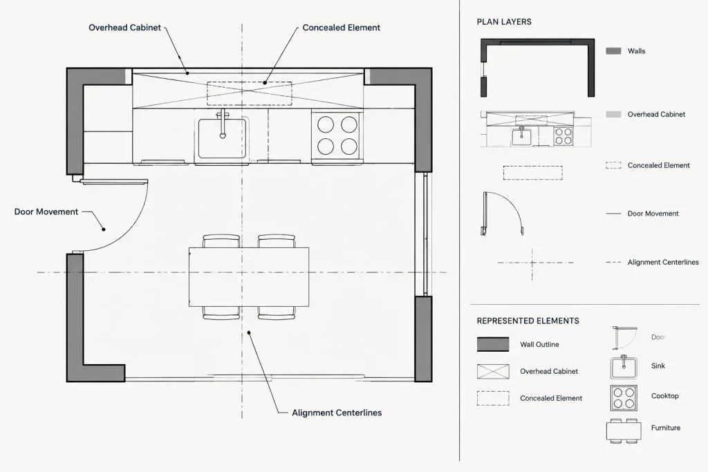
A useful layer name identifies the discipline or drawing role, the element, and the graphic condition where appropriate. An overhead cabinet line, for example, should not be placed on a miscellaneous dashed layer shared with property information and concealed structure. Those elements may look similar in one viewport but have different coordination and visibility requirements.
Object-level overrides are sometimes necessary, but they should be deliberate and limited. Excessive overrides make it difficult to diagnose why one line plots differently from similar objects. Before overriding an object, consider whether it represents a separate drawing category that deserves its own layer.
Choose Patterns That Remain Distinguishable
A drawing does not benefit from having many patterns if readers cannot tell them apart. Select a small, controlled group of linetypes with clearly different rhythms. Two nearly identical dashed patterns may be distinguishable at high zoom but appear the same on a printed or reduced sheet.
Complex linetypes containing text or shapes can be useful for utilities, fences, limits, or specialized site information. They also require more testing because their orientation, spacing, text style dependencies, and appearance around short or curved objects may vary. Use them only when they add information that a simple pattern and clear label cannot communicate as effectively.
Control Linetype Scale Systematically
Linetype scale controls the displayed length and spacing of a repeating pattern. If the scale is too small, dashes may merge into what looks like a continuous line. If it is too large, short objects may display only one dash or no recognizable pattern.
AutoCAD drawings can be affected by global linetype scale, individual object scale, model-space display settings, annotation scale, and paper-space viewport behavior. Rather than adjusting these controls randomly, use a repeatable process:
- Confirm the drawing units and intended plotting workflow.
- Review the project’s global linetype scale setting.
- Keep individual object linetype scales consistent unless a documented exception is required.
- Check model-space display, but make final judgments in the plotted sheet viewport.
- Regenerate the drawing after changing scale-related settings.
- Test both long and short objects, including arcs and closed polylines.
The familiar AutoCAD controls LTSCALE, CELTSCALE, PSLTSCALE, and MSLTSCALE affect different parts of this behavior. Their appropriate configuration depends on whether the office expects patterns to appear consistently in paper space, scale with model-space annotation settings, or follow another established template method. Avoid changing one variable merely to fix a single object before understanding the project-wide effect.
Coordinate Linetypes Across Viewports
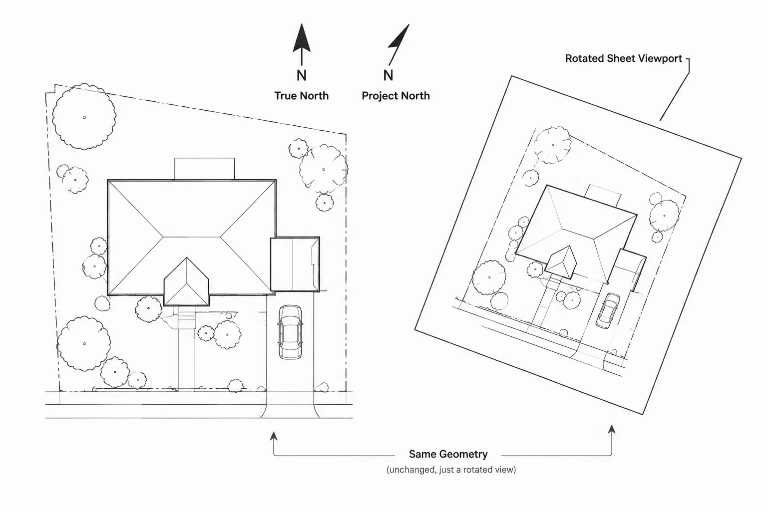
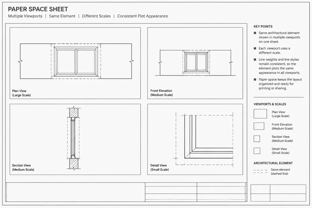
A model may be shown through several viewports at different scales. The same overhead line or hidden edge should retain a comparable graphic meaning across those views, even if the visible dash spacing is managed through the sheet setup.
Review linetypes in the actual layouts, not only in model space. Check whether:
- The pattern reads clearly at each viewport scale.
- Short segments still appear dashed where necessary.
- Patterns remain visually distinct after plotting to monochrome.
- Clipping boundaries or viewport crops create misleading fragments.
- Lineweight does not fill the gaps in a fine dashed pattern.
- Reduced-size prints preserve enough contrast to understand the drawing.
If one viewport requires a completely different object-level scale to remain legible, investigate the sheet and linetype settings before creating duplicate geometry.
Avoid Ambiguous Dashed Information
Dashed lines are frequently overused because they provide a quick way to make an object look secondary. However, readers need to know why the line is secondary. It may represent something above, below, hidden, existing, removable, movable, or outside the scope of work. These meanings are not interchangeable.
Support linetypes with layer names, notes, labels, symbols, or legends when the condition is not self-evident. Demolition and phase information should follow the project’s documented graphic system rather than relying on a generic dashed pattern. Likewise, life-safety, property, and legal boundary information should not be inferred solely from a line appearance.
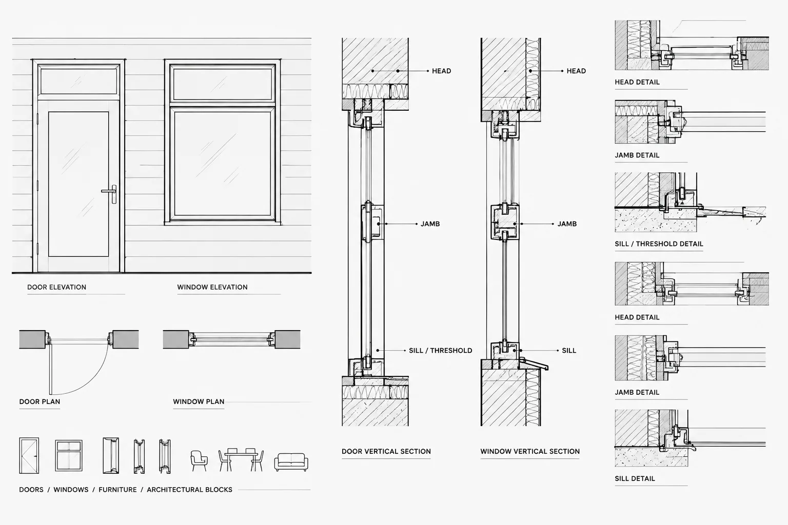
Clean Linetypes in Referenced and Downloaded DWG Files
External references and downloaded CAD blocks often introduce duplicate or unfamiliar linetype definitions. Some may have similar names but different patterns, while others depend on missing shape or text resources. Do not automatically adopt these definitions into the architectural template.
When reviewing an incoming file:
- Identify which linetypes are actually used.
- Compare their purpose with the project’s established categories.
- Move geometry to appropriate project layers where permitted.
- Remove unnecessary object-level overrides.
- Check complex patterns for missing resources or substituted text.
- Keep consultant information recognizable when it must remain unchanged.
- Test the result in a sheet viewport before finalizing the cleanup.
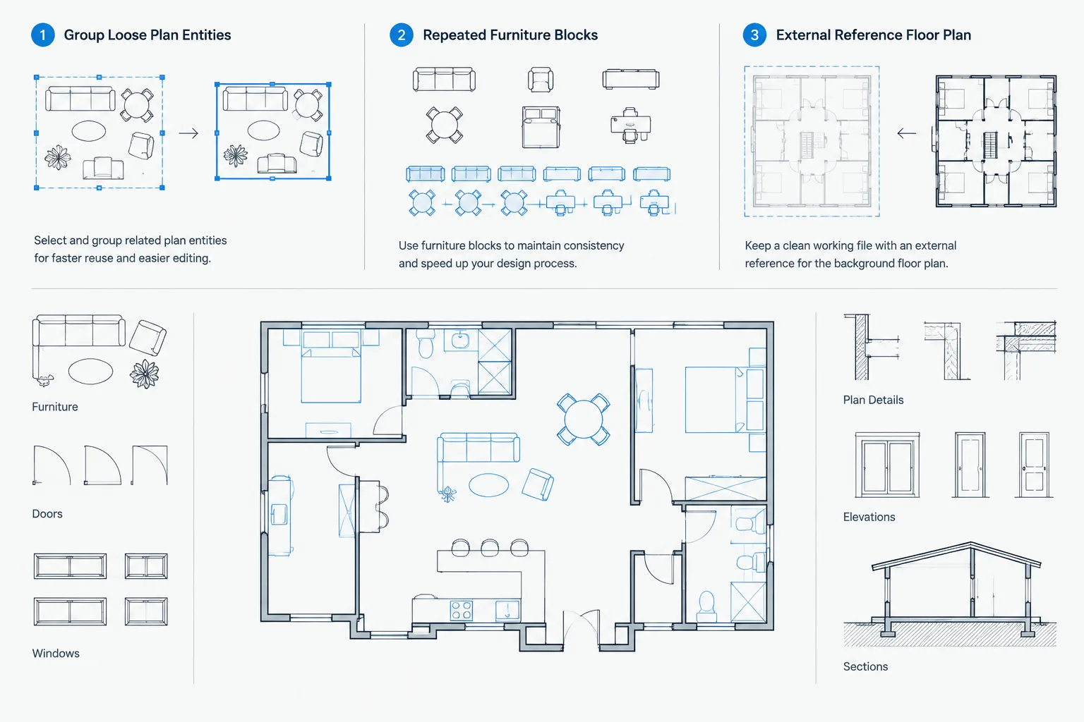
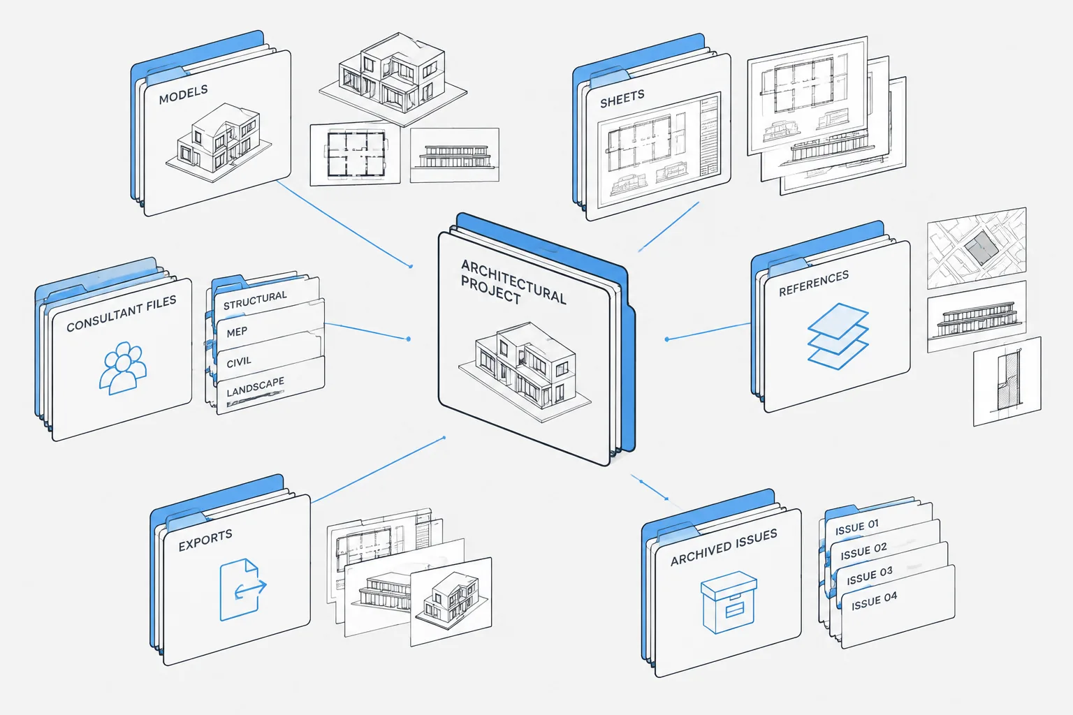
When an external reference must preserve the consultant’s graphics, control its appearance through the agreed reference and layer workflow rather than editing the source file without coordination.
Practical Linetype Quality-Control Checklist
- Every noncontinuous pattern has a clear drawing purpose.
- Objects inherit linetype properties from their layers wherever practical.
- Similar-looking patterns do not carry conflicting meanings.
- Dash spacing is legible at the intended plot scale.
- Short lines, arcs, and polylines display recognizable patterns.
- Overhead and hidden elements agree with related plans, elevations, and sections.
- Viewport settings produce consistent sheet graphics.
- Monochrome and reduced plots remain readable.
- Imported linetypes and object overrides have been reviewed.
- Legends and notes explain project-specific conventions.
Keep the Graphic System Simple
The best architectural CAD linetype system is not the one with the most patterns. It is the one that helps a reader understand the drawing quickly and consistently. Use layers to preserve meaning, use lineweights to establish hierarchy, and verify patterns in the final sheet context.
A disciplined linetype workflow also makes DWG files easier to coordinate. When overhead, concealed, boundary, and movement information each have a defined graphic role, other team members can isolate, compare, and revise those categories without guessing how the file was constructed.
A Diagnostic Workflow for Linetype Problems
When a pattern looks wrong, begin by identifying whether the problem affects one object, one layer, one viewport, or the entire drawing. That distinction helps prevent a local display issue from being addressed with a drawing-wide change.
If One Object Looks Different
- Check whether the object inherits its linetype from the layer or uses an object-level override.
- Compare its individual linetype scale with nearby objects serving the same purpose.
- Confirm that the object is long enough to display a recognizable portion of the pattern.
- Inspect joined segments, arcs, and polylines for behavior that interrupts the visual rhythm.
If an Entire Layer Looks Wrong
- Verify that the layer has the intended linetype assignment.
- Confirm that its meaning is not duplicated by another layer with a conflicting convention.
- Review whether imported geometry introduced an unfamiliar or dependent linetype definition.
- Check the plotted lineweight because a heavy stroke can visually close small gaps.
If Viewports Do Not Match
- Compare the viewport scales and relevant model-space and paper-space linetype behavior.
- Regenerate the drawing and inspect the result in the layout rather than relying on model-space appearance.
- Look for viewport-specific layer overrides that may change the graphic category.
- Use a plot preview or test output to judge the final pattern, weight, and contrast together.
Linetype Decisions Should Follow Drawing Meaning
Before changing a pattern, state what the line represents in plain language. If the answer is unclear, the issue may be classification rather than scale. An overhead element, concealed component, movement path, and project boundary can all appear dashed, but they should not become interchangeable simply because they share a secondary visual character.
A well-structured drawing lets reviewers trace each graphic condition back to a meaningful layer, legend entry, note, or coordinated convention. This approach improves both sheet readability and DWG maintenance because future revisions can be made by category instead of by searching for isolated overrides.
Architectural CAD Linetype FAQ
What is the difference between linetype and lineweight?
Linetype describes the repeating pattern and usually communicates a condition such as hidden, overhead, centered, movable, or bounded. Lineweight controls visual emphasis and helps distinguish cut elements, profiles, surfaces, and fine information. Clear architectural drawings coordinate both properties rather than asking either one to carry all graphic meaning.
Why does a dashed line appear continuous?
The pattern may be too dense for the object length, viewport, plotted lineweight, or current scale settings. Check the object and layer properties, review the drawing’s linetype controls, regenerate the file, and judge the result in the intended sheet layout.
Why does a short line show no recognizable pattern?
A short object may not contain enough length to display the selected dash-and-gap sequence clearly. Confirm that the pattern is appropriate for the object and test the plotted result before applying an isolated override.
Should architectural objects use layer-based linetypes?
Layer-based assignment is generally the clearest approach because related objects can be managed consistently. Object-level overrides may be appropriate for documented exceptions, but extensive overrides make troubleshooting and coordination more difficult.
Can the same dashed pattern represent overhead and hidden elements?
It can only do so safely when the drawing system provides another clear way to distinguish the meanings. Separate layers, labels, notes, lineweights, or legends may be needed to prevent ambiguity.
How should imported DWG linetypes be handled?
Review their purpose before adopting them. Check for duplicate definitions, unfamiliar names, object overrides, and dependencies on text or shape resources. Preserve consultant graphics when required, but manage their appearance through the agreed coordination workflow.
Where should linetypes be checked before a drawing is issued?
Review them in the actual sheet layouts and intended plotting conditions. Model-space appearance alone may not reveal viewport scaling, clipping, lineweight interaction, monochrome output, or reduced-print readability.