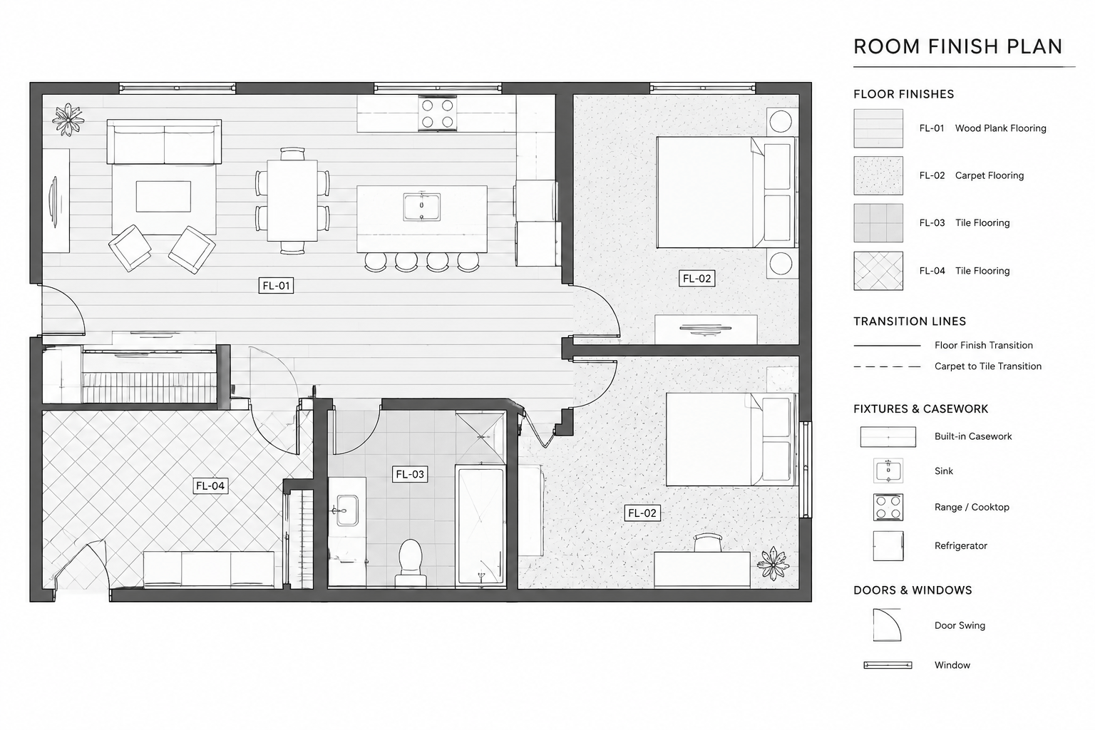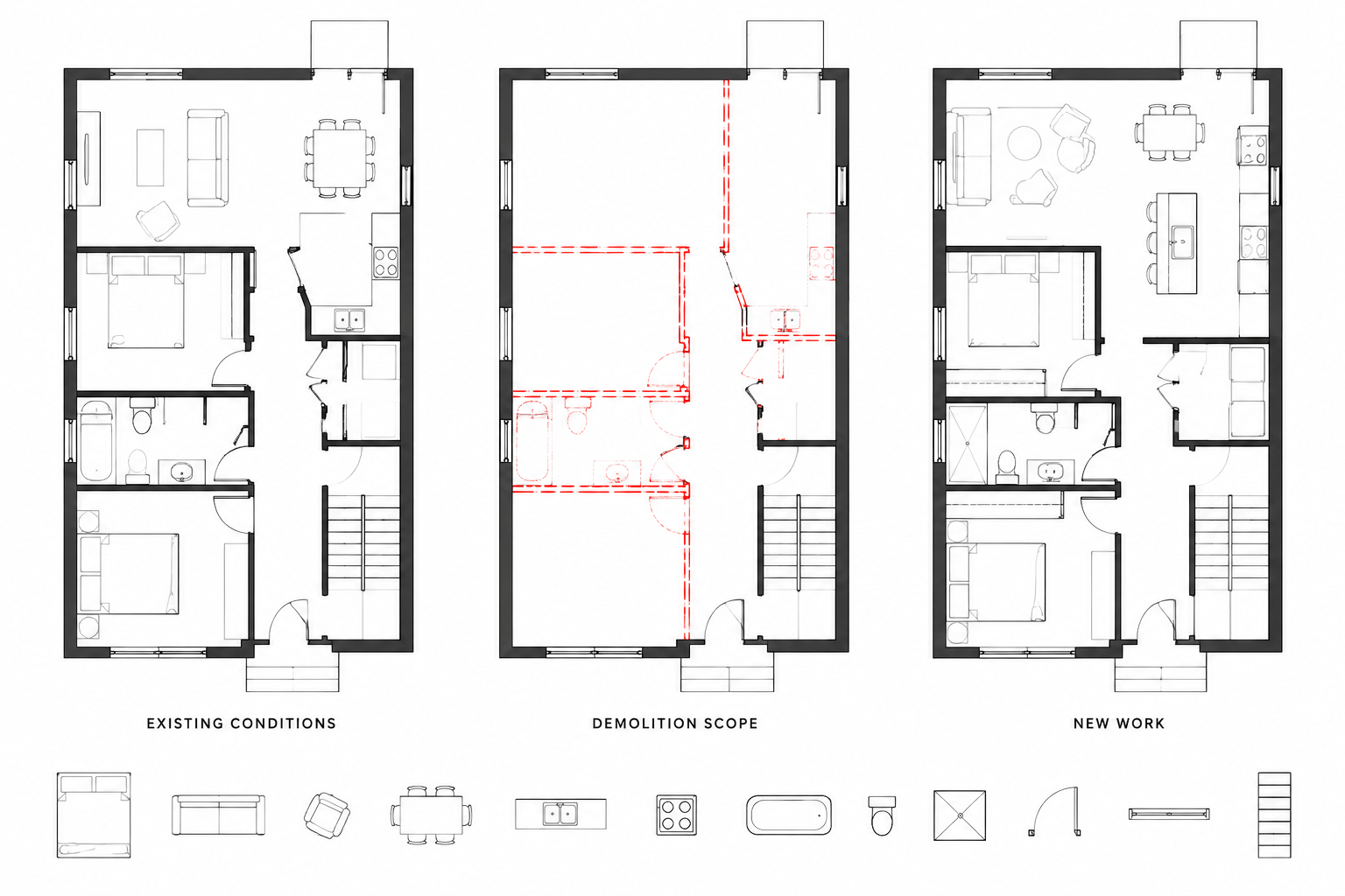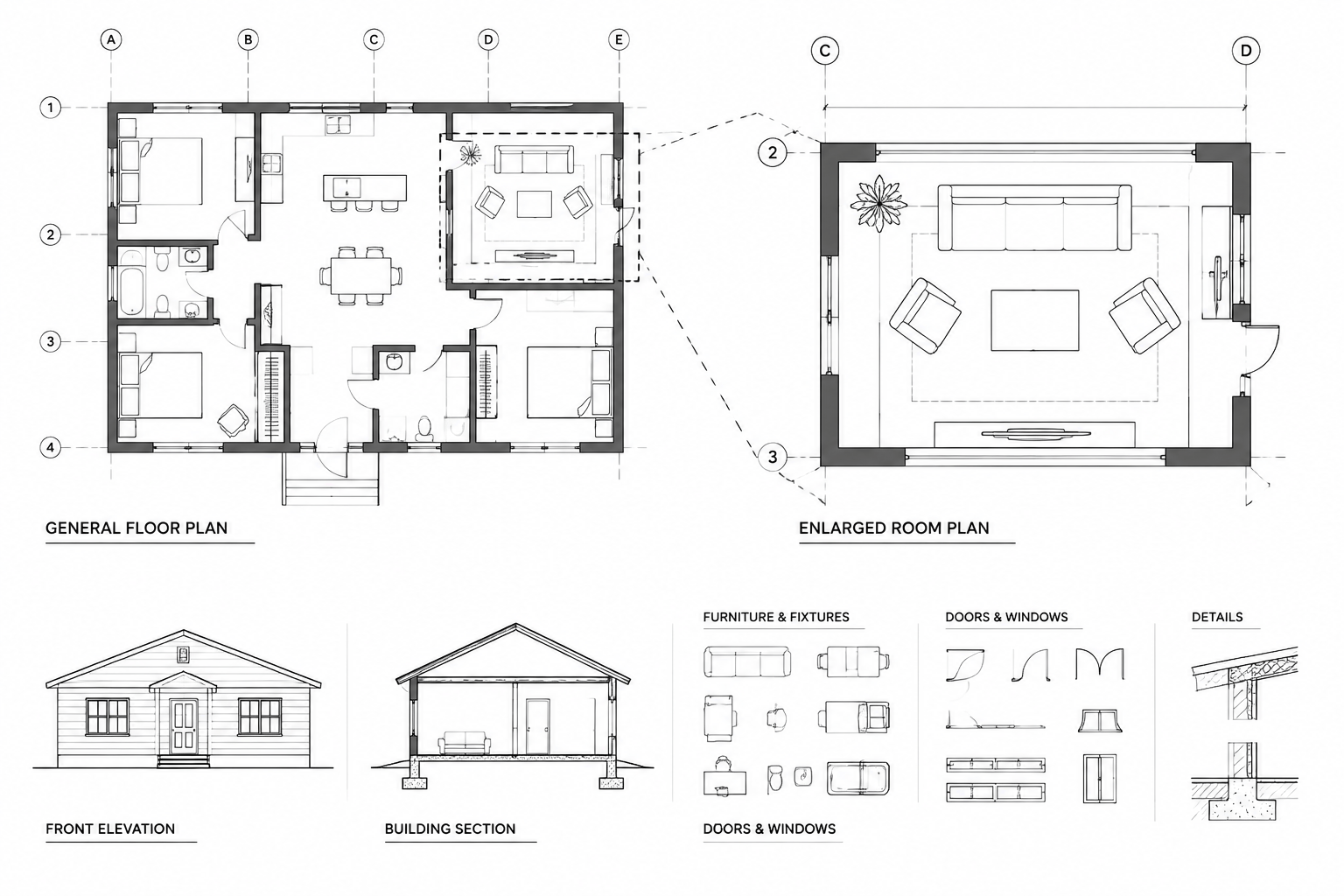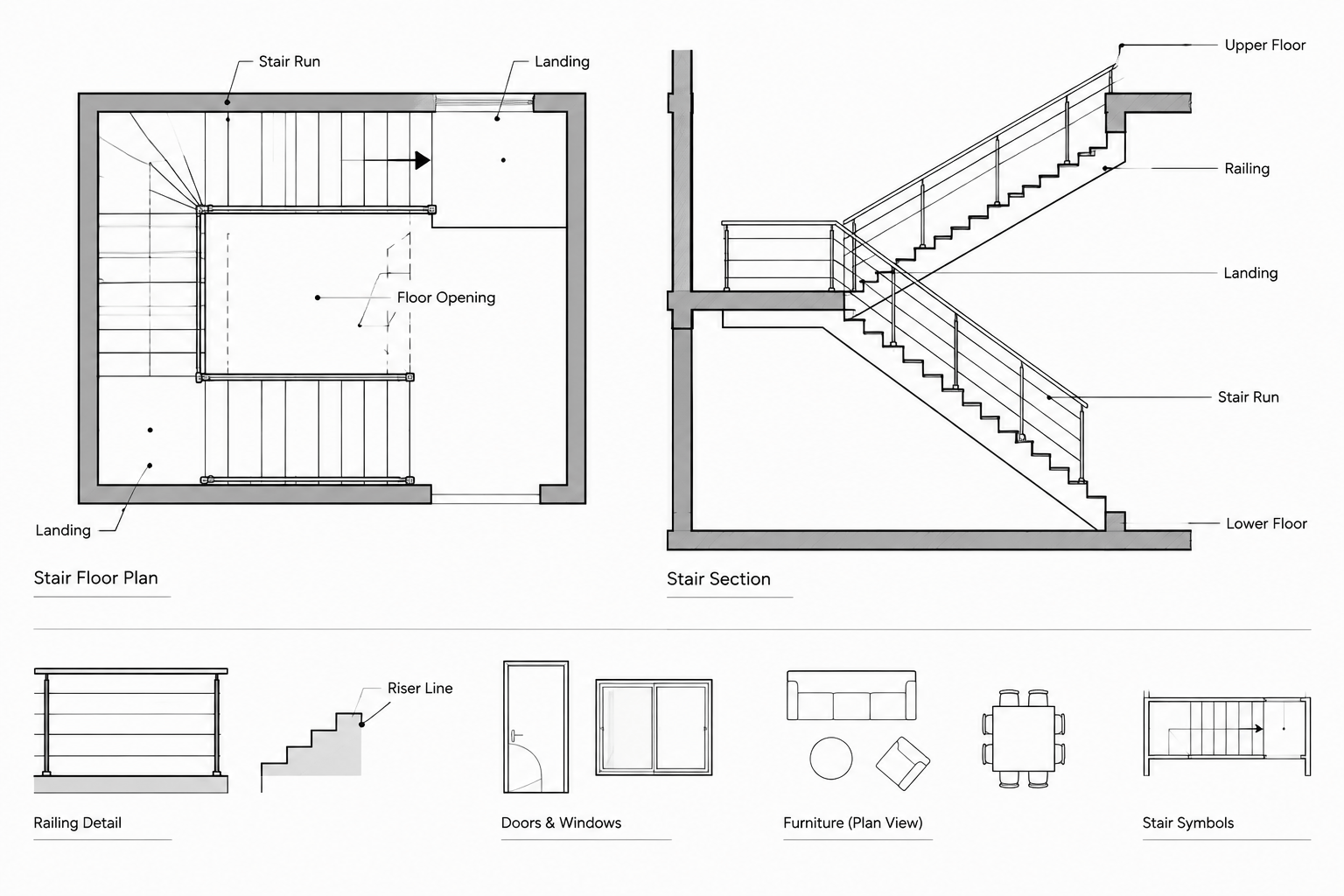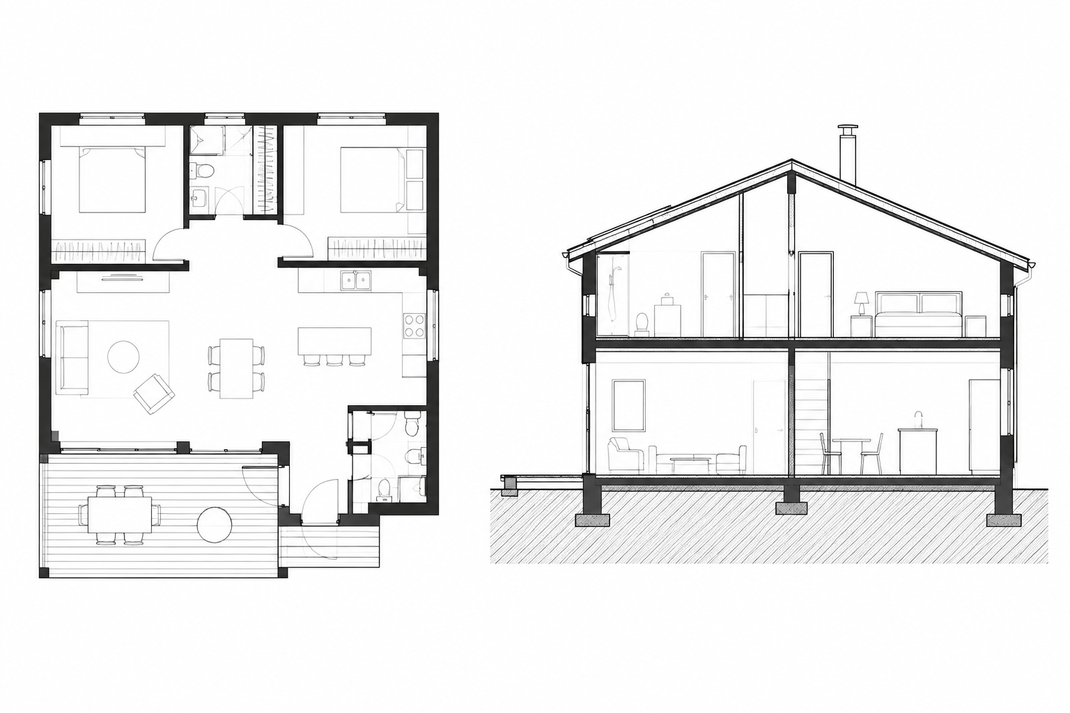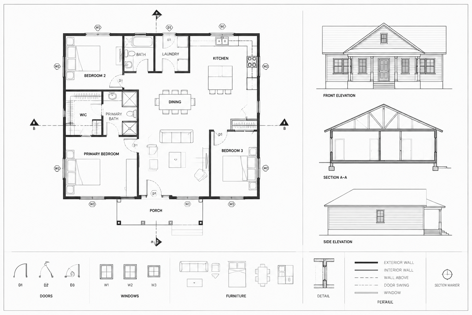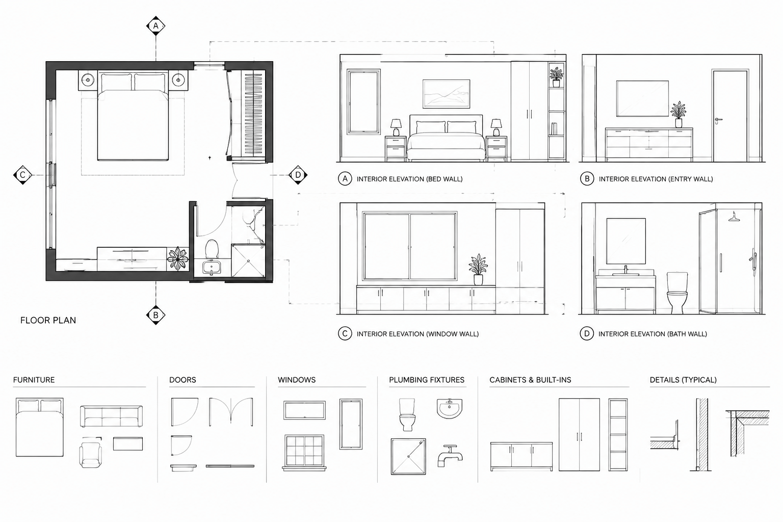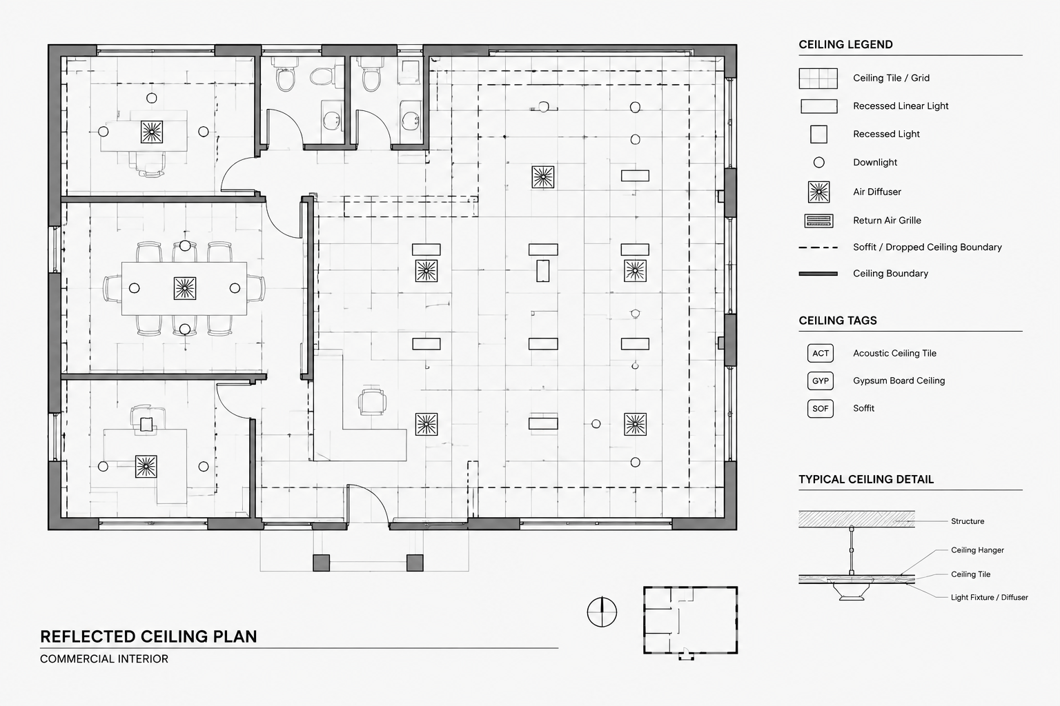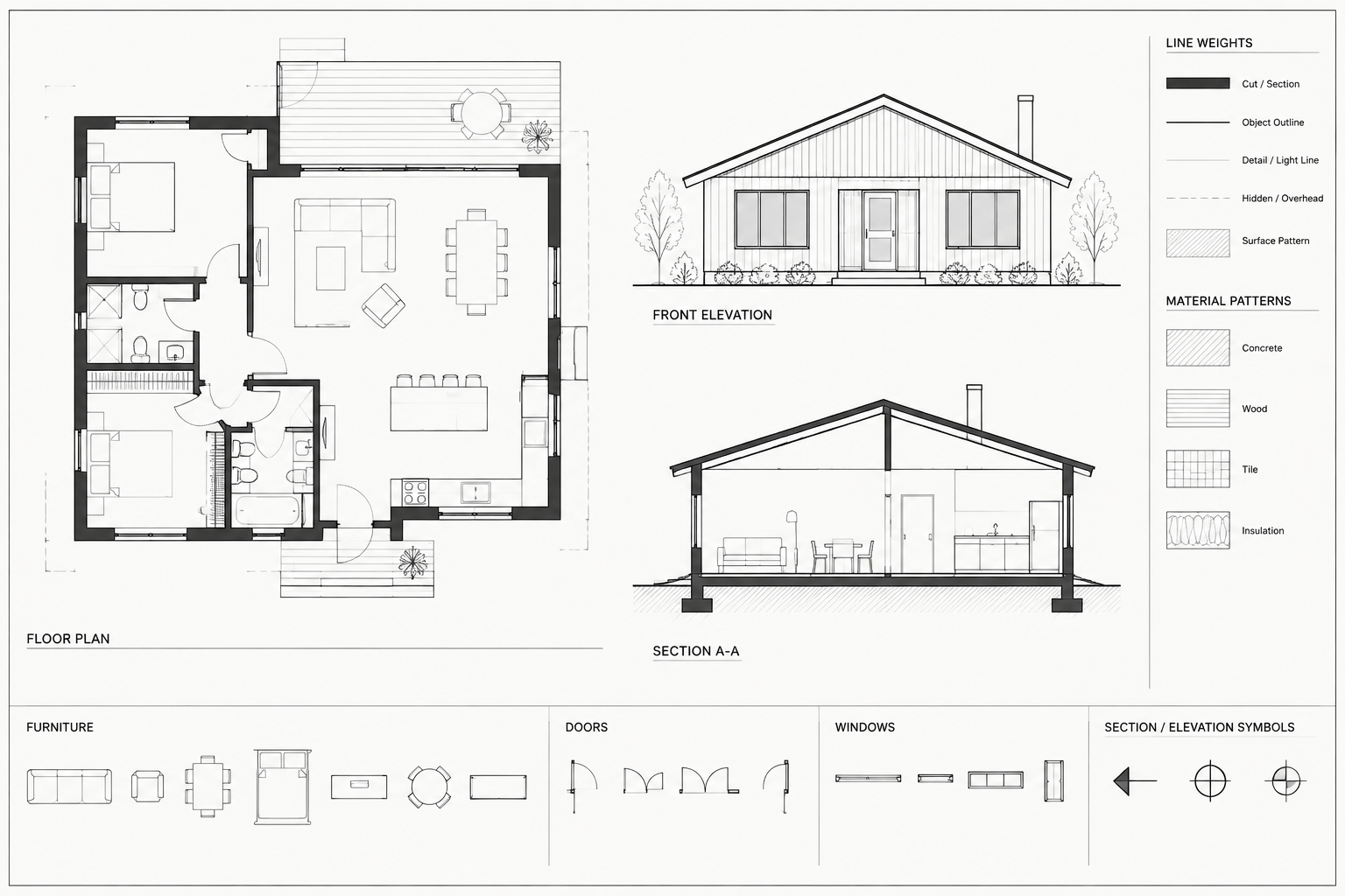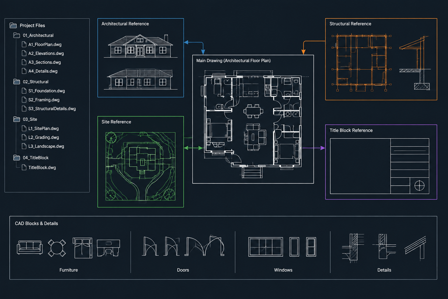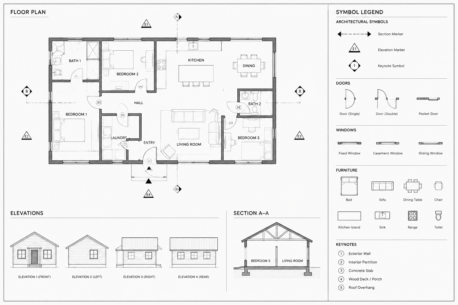
Architectural plan symbols compress a large amount of information into small, repeatable graphic elements. A door tag can connect an opening to a schedule, a section marker can direct the reader to another drawing, and a material symbol can explain construction without filling the plan with text. When these symbols are inconsistent, however, the drawing set becomes harder to navigate and easier to misinterpret.
A reliable CAD symbol system is not simply a folder of blocks. It is a coordinated method for deciding what each symbol means, where it appears, how it is displayed, and how it connects to schedules, notes, details, and sheet references. The following workflow can help architects and drafters build clearer symbol libraries and drawing legends without assuming that one office convention applies to every project.
Understand the Different Types of Plan Symbols
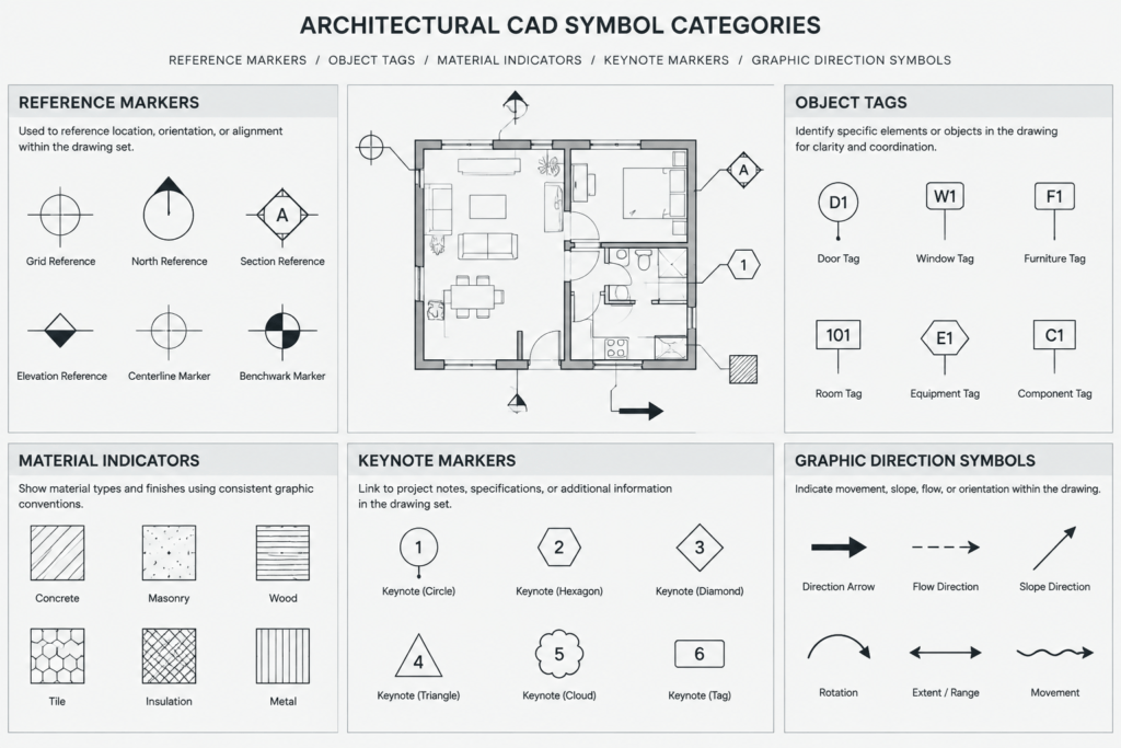
Before creating blocks, separate symbols by purpose. Symbols that look similar may perform very different jobs, and combining them without a clear structure can create coordination problems.
| Symbol category | Typical purpose | Coordination concern |
|---|---|---|
| Reference markers | Direct readers to sections, elevations, details, or enlarged plans | Drawing and sheet references must match the destination view |
| Object tags | Identify doors, windows, rooms, equipment, fixtures, or finishes | Identifiers must agree with schedules and related plans |
| Graphic indicators | Show items such as north direction, slopes, levels, or break locations | Meaning and orientation must be clear in the drawing context |
| Material symbols | Represent materials in plans, sections, elevations, or details | Patterns should remain legible and consistent across views |
| Keynote markers | Connect a numbered or coded reference to a note list | Unused, duplicate, or incorrect references must be removed |
| Status and scope symbols | Identify work boundaries, match lines, revision areas, or related conditions | The symbol must reflect the current issue of the drawing set |
Some symbols are widely recognizable, but their exact graphics and meanings can vary among firms, consultants, project types, and authorities. Treat office libraries as starting points rather than proof that a symbol is appropriate for every drawing set.
Start with a Project Symbol Inventory
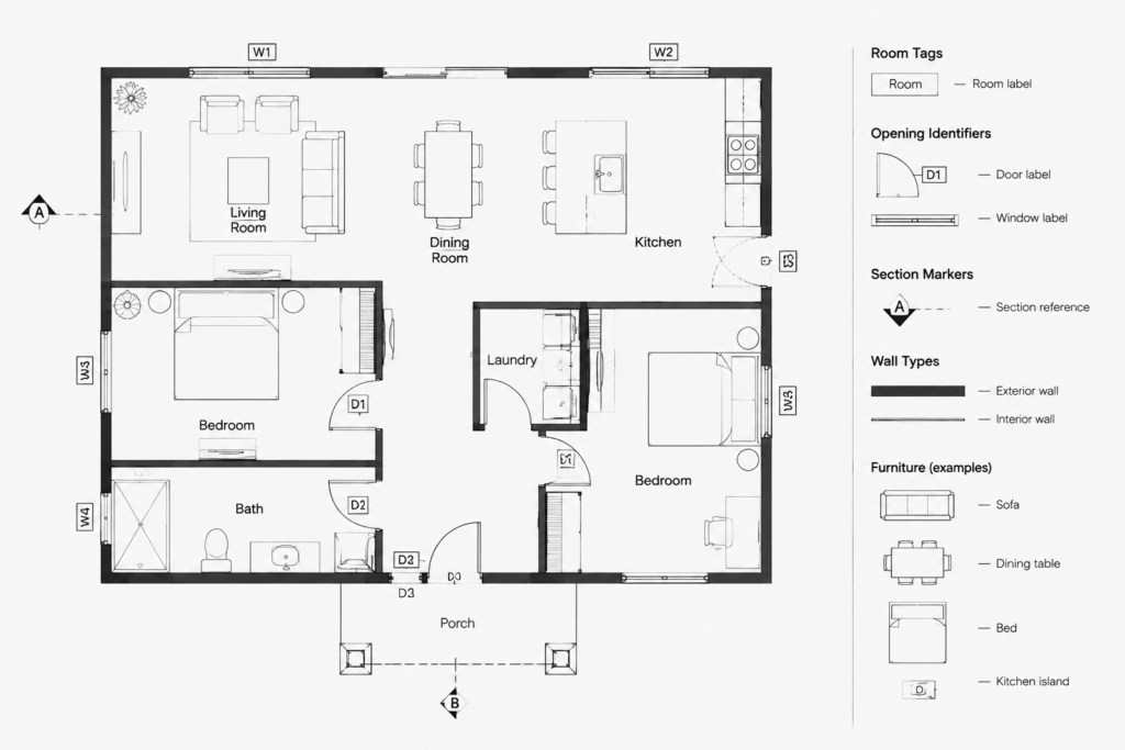
Do not place every available symbol in a project legend. Begin by identifying what the project actually needs. Review the proposed sheet list, drawing types, schedules, consultant backgrounds, and annotation strategy. A floor plan may require room tags and opening identifiers, while a wall section may rely more heavily on material indications and detail references.
A simple inventory can record:
- The symbol name and intended meaning
- The drawing types where it may appear
- Whether it links to a schedule, note, detail, or other sheet
- The responsible discipline or drawing author
- The source CAD block or annotation object
- Whether the symbol belongs in a general legend or a sheet-specific key
This step exposes unnecessary duplicates early. For example, a project should not casually use several different room-tag blocks unless each variation has a defined purpose.
Create Symbols for Readability at the Plotted Sheet
Symbols should be evaluated in their final plotted context, not only while zoomed in on model space. A marker that looks clean on screen may become crowded when placed near walls, dimensions, hatches, and furniture.
Keep the geometry simple
Use only enough linework to communicate the symbol’s function. Excessive circles, borders, fills, or decorative geometry can compete with the information inside the marker. Simpler symbols are also easier to maintain when office graphics change.
Protect the text area
Allow room for realistic project identifiers rather than testing a block with only the shortest possible label. Door numbers, detail references, room names, and keynote codes can vary in length. Text should not touch marker boundaries or overlap nearby annotation.
Use a deliberate graphic hierarchy
The symbol should be visible without overpowering the building geometry. Reference markers generally need enough emphasis to be found quickly, while secondary notes may be lighter. Confirm the result through test plots using the project’s actual plotting method.
Avoid using color alone to convey meaning
Colors may help users work inside CAD, but printed, exported, or reproduced sheets may not preserve those distinctions. Shape, label, line pattern, or another visible graphic difference should carry the essential meaning.
Build CAD Blocks with Controlled Behavior
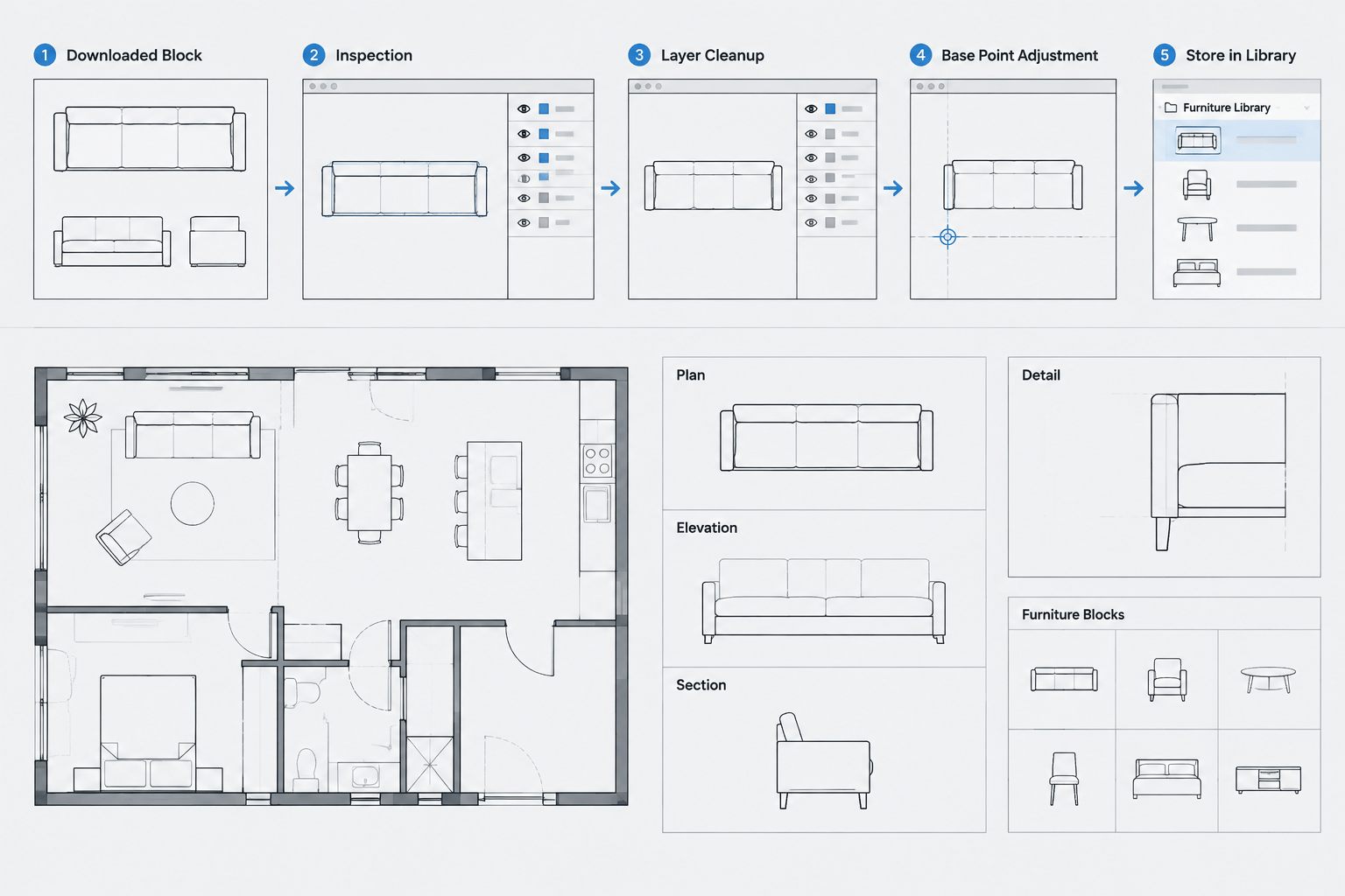
A symbol block should behave predictably when inserted, copied, rotated, and edited. Establish a logical insertion point based on how the symbol will be placed. A room tag may be positioned from its center, while a leader-based marker may need a base point at the leader connection.
Review each block for the following:
- Unnecessary nested blocks, duplicate lines, and hidden geometry
- Stray objects located far from the visible symbol
- Text styles or properties imported from unrelated files
- Unexpected lineweights, linetypes, fills, or transparency settings
- Attribute prompts that are unclear or ordered poorly
- Geometry assigned to inappropriate layers
- An insertion point that makes placement difficult
Where attributes are used, give each field a clear purpose. Do not use one field for several unrelated kinds of information merely because the text appears in the same position. Clear attribute names make later editing and checking more reliable.
Choose a Consistent Layer Strategy
Symbols and their text need a layer strategy that supports visibility control and plotting. The exact layer names should follow the project’s CAD standard, but the underlying logic should remain consistent.
Consider whether reference symbols, object tags, keynote markers, and general annotation need separate visibility controls. Separating meaningful categories can be useful when producing presentation plans, coordination backgrounds, or specialized drawing views. Creating a unique layer for every individual symbol, however, can make the file difficult to manage.
Decide whether block geometry should inherit properties from the insertion layer or retain assigned internal properties. Either approach can work when applied intentionally. Mixing methods across similar blocks often produces unpredictable plots and time-consuming cleanup.
Coordinate Symbols with the Information They Reference
The most serious symbol problems are usually coordination errors rather than drafting errors. A beautifully drawn section marker is still wrong if it points to a nonexistent drawing.
Reference markers
Check that every section, elevation, detail, and enlarged-plan marker leads to the correct drawing and sheet. Also check the destination view for a corresponding title or identifier. Renumbering sheets late in a project can break this relationship if references are not reviewed.
Doors, windows, and equipment tags
Compare identifiers against the relevant schedules and plans. Look for missing tags, duplicate identifiers, demolished items that remain scheduled, and scheduled items that cannot be found in the drawing.
Room and finish references
Confirm that room names and identifiers agree across floor plans, finish information, reflected ceiling plans, and other related drawings. A room tag should not become an isolated label maintained independently from the rest of the set.
Keynotes
Every keynote marker should have a valid note, and every listed note should be reviewed for actual use. Reusing a note code for a different meaning can create ambiguity, particularly when notes are copied between projects.
Build Legends from Symbols Actually Used
A legend should help the reader interpret the current drawing set. A large generic legend filled with unused symbols makes it harder to identify relevant information and may imply that conditions exist when they do not.
Choose the legend location according to its scope:
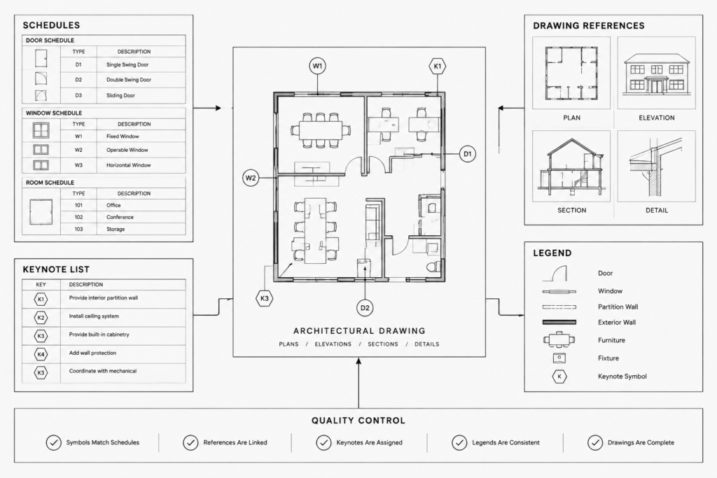
- A general symbol legend can explain conventions used throughout the architectural set.
- A plan-specific legend can identify symbols unique to a drawing type.
- A material key can support sections and details using the same graphic conventions.
- A sheet-specific key can clarify unusual symbols that appear only in one location.
Keep the symbol shown in the legend graphically consistent with the symbol in the drawing. Redrawing a look-alike symbol inside a table creates another item that must be maintained. When practical, use the same controlled source block.
Distinguish Symbols, Abbreviations, and Notes
A symbol key, abbreviation list, and general notes are related but not interchangeable. A symbol key explains graphic marks. An abbreviation list defines shortened terms. General notes communicate broader instructions or drawing conventions.
Separating these functions improves scanning and reduces bloated legends. If a marker requires a paragraph to explain it, the underlying annotation method may need to be simplified or supported by a dedicated note.
Use a Repeatable Quality-Control Pass
Symbol review should occur before a drawing issue and after significant changes to sheet organization, schedules, or view numbering. A practical check includes:
- Search for duplicate or missing identifiers.
- Trace reference markers to their destination drawings.
- Compare tags with schedules and related plan types.
- Confirm that legend entries are current and actually used.
- Review symbols near crop boundaries, match lines, and viewport edges.
- Check for mirrored or rotated text.
- Plot representative sheets and inspect symbols at normal reading size.
- Verify that consultant symbols are not mistaken for architectural symbols.
- Remove obsolete blocks left from copied backgrounds or earlier design options.
Automated extraction or data tools may assist with coordination, but visual review remains important. Symbols can be technically present and still be unreadable, poorly positioned, or misleading in context.
Maintain a Library Without Freezing Project Judgment
A shared symbol library can improve consistency, but it should have an identifiable owner and a controlled update process. Store a clean source for each approved office symbol, along with a short description of its purpose. Avoid keeping several nearly identical files with unclear names.
When a project requires a variation, determine whether the change belongs only in that project or should be incorporated into the shared library. Replacing a library block without review can affect older details or introduce incompatible annotation into active files.
Most importantly, treat symbols as part of the drawing’s information system rather than decoration. Their value comes from reliable relationships: tags to schedules, markers to views, keys to notes, and legends to actual drawing content. A small, coordinated set of readable symbols is more useful than a large collection of blocks with uncertain meanings.