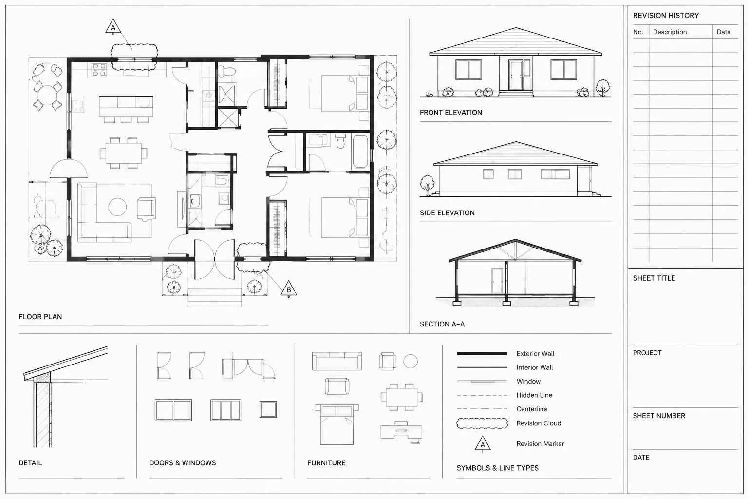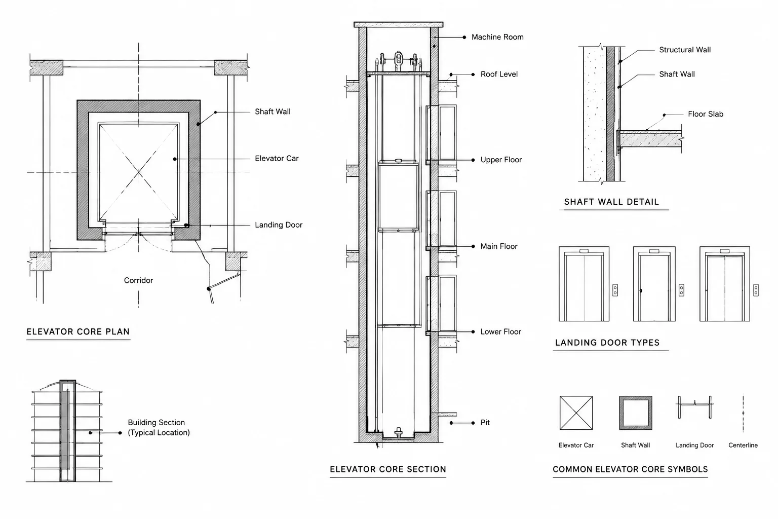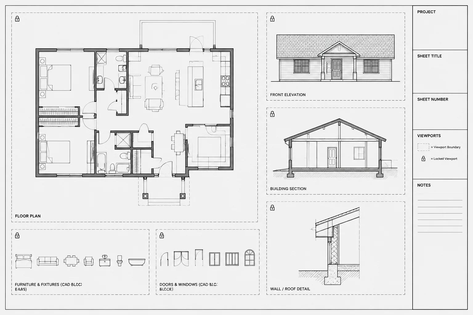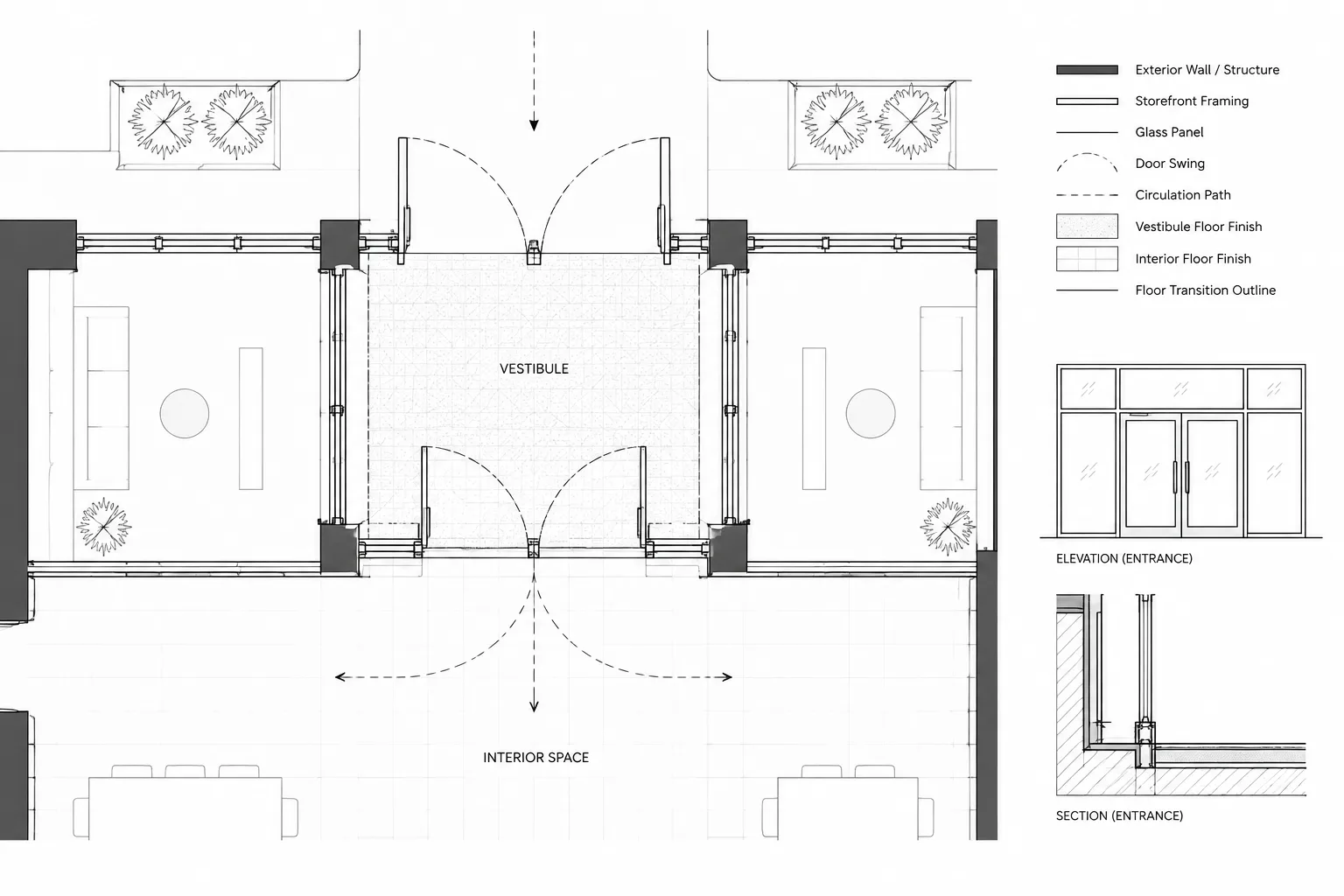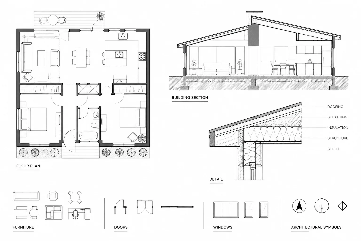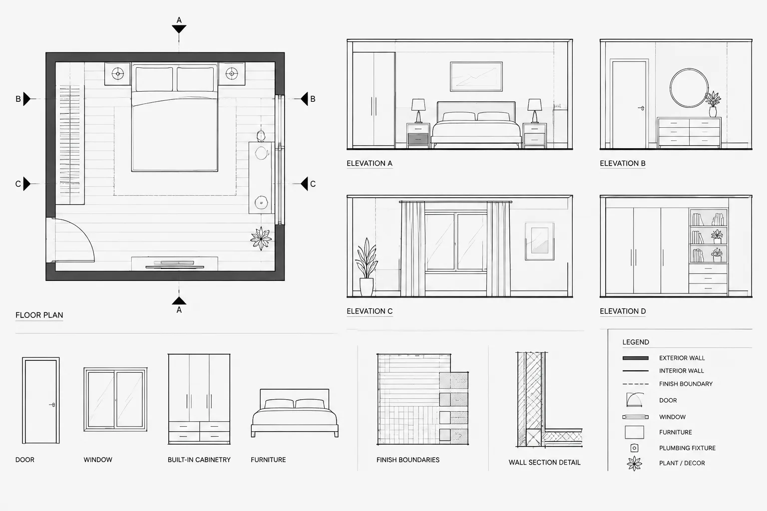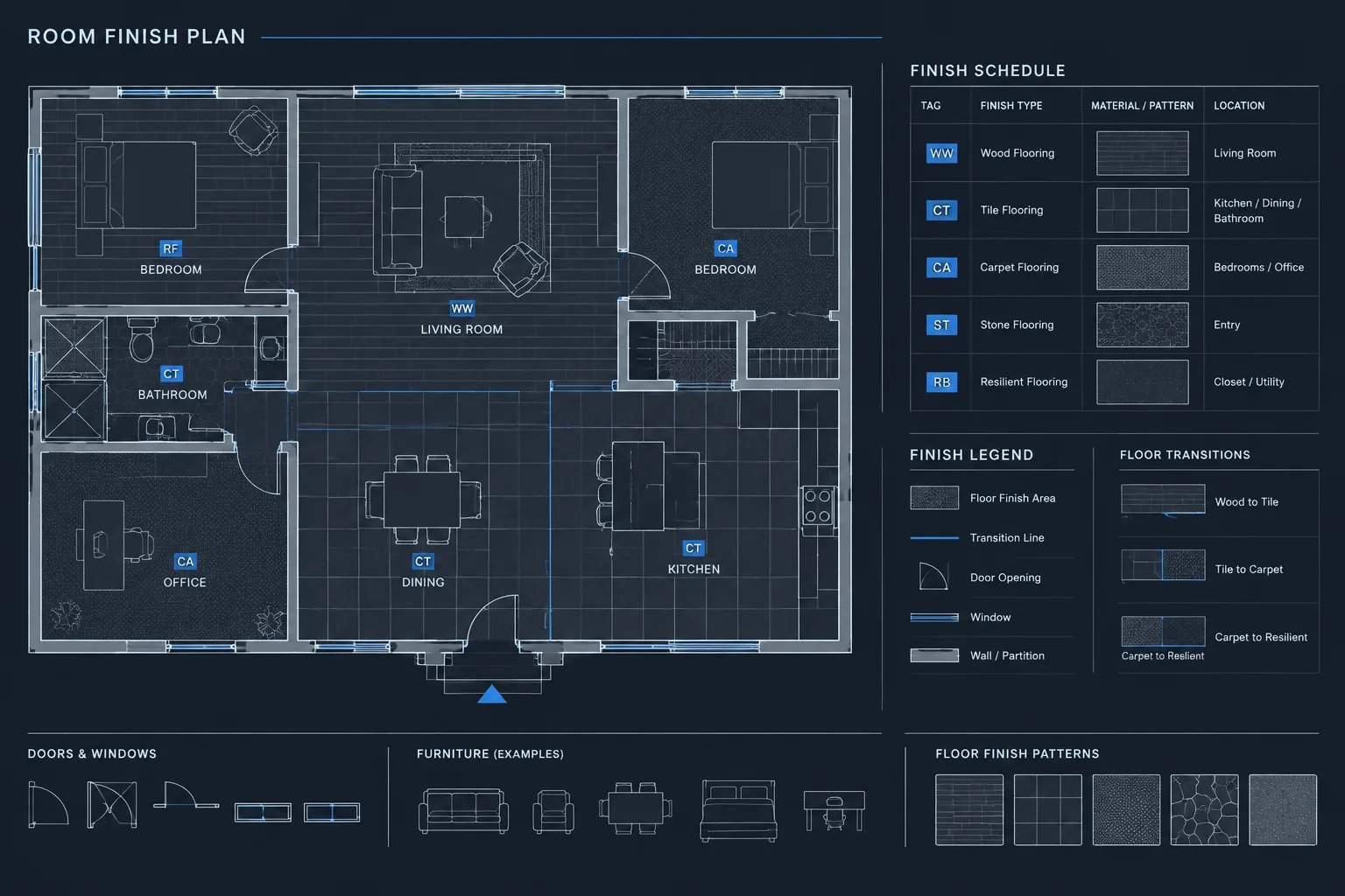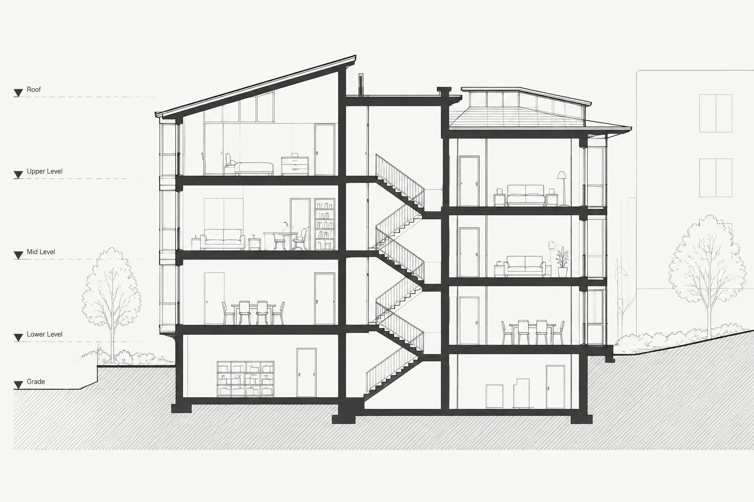
Drafting a building section requires more than projecting plan geometry into a vertical view. The section must reconcile levels, openings, circulation, roof conditions, grade, and visible background elements while remaining clear at its intended drawing scale.
The following workflow explains how to select an informative cut, establish reliable references, organize CAD linework, and check the completed section against related architectural drawings. It is intended as a drafting and coordination guide; project assemblies and compliance requirements still require review by the responsible design professionals.
A building section explains vertical relationships that a floor plan cannot show clearly. It cuts through floors, roofs, walls, openings, stairs, and other major elements to reveal how the building is organized from foundation to roof. A useful section is not simply an elevation with heavier lines. It is a coordinated drawing built around a defined cut plane, a deliberate viewing direction, and a clear graphic hierarchy.
This guide presents a practical workflow for drafting building sections in architectural CAD. It focuses on drawing organization, projection, coordination, and quality control rather than project-specific construction requirements. Actual assemblies, dimensions, and regulatory criteria must be verified for the project and jurisdiction.
Building Section vs. Wall Section
A building section typically passes through a substantial portion of the structure and communicates major spatial and vertical relationships. It may show multiple floors, roof forms, stairs, ceiling zones, grade, and important openings. Its purpose is broad coordination and an understanding of the building as a whole.
A wall section is usually more focused. It enlarges a limited portion of the enclosure to explain layers, connections, transitions, and construction details. A building section may indicate where wall sections or larger details are needed, but it should not attempt to carry every piece of assembly information.
Keeping these roles separate prevents the building section from becoming overloaded. Show enough construction information to explain the design, then refer to larger views for conditions that require more detail.
Choose a Section Cut That Explains the Building
Before drawing, decide what the section needs to communicate. A productive cut often passes through several meaningful conditions rather than an arbitrary open area. Depending on the project, these conditions may include:
- A major entrance or circulation route
- A stair, ramp, atrium, or other vertical connection
- A change in floor or roof level
- Important exterior openings
- A sloped roof, parapet, canopy, or terrace
- A relationship between occupied space and grade
- A transition between major construction systems
A single section does not need to explain everything. Several carefully selected cuts are usually clearer than one section distorted to include unrelated conditions.
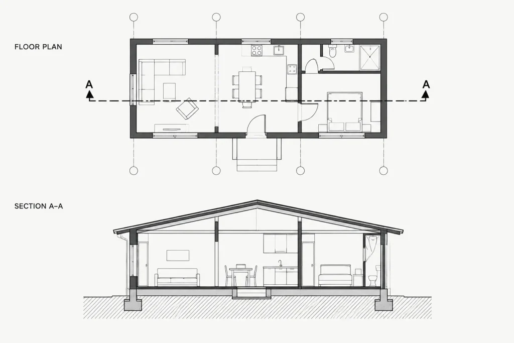
Coordinate the Cut Line on the Plan
Place the section line on the source plan and confirm its viewing direction before projecting geometry. The plan marker and the section view must agree. If the cut jogs, make each change in the cutting plane understandable and avoid creating a misleading composite of spaces that do not actually align.
Check whether the section line passes directly through doors, windows, stairs, columns, shafts, and other features. A small plan adjustment can significantly change what appears cut and what appears beyond.
Establish Reliable Horizontal and Vertical References
Begin the CAD section with dependable reference geometry. Horizontal control generally comes from levels, while lateral control comes from grids, major wall faces, or other project datums. These references should match the coordinated project drawings rather than being recreated from visual estimation.
Useful setup geometry may include:
- Floor and roof level lines
- Structural grid locations
- Exterior wall control faces
- Major interior partition locations
- Finished grade and significant site breaks
- Ceiling or soffit control lines where relevant
Keep temporary projection lines on a dedicated non-plotting or construction layer. This allows the drafter to trace relationships without mixing working geometry into the final section graphics.
Project Geometry from Coordinated Sources
Use the current floor plans, roof plan, exterior elevations, structural backgrounds, and relevant consultant information as coordinated sources. Avoid relying on an older section as the sole basis for a revised one. Sections can preserve obsolete floor heights, openings, or roof conditions long after plans have changed.
A practical projection sequence is:
-
Transfer grid lines and major horizontal positions from the plan.
-
Establish floor, roof, landing, and grade elevations from the project datums.
-
Draw the primary cut elements, including slabs, walls, roofs, and major structure shown by the architectural documents.
-
Add openings and vertical circulation that intersect the cut plane.
-
Draw visible elements beyond the cut, using lighter graphics.
-
Add ceilings, soffits, casework, fixtures, and other secondary elements only where they improve understanding.
Projection does not mean copying every plan line into the section. Decide whether an object is cut, visible beyond, hidden, or irrelevant to the view.
Build a Clear Graphic Hierarchy
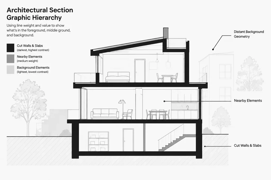
The most important distinction in a section is between material cut by the section plane and objects seen beyond it. Without this hierarchy, the drawing reads like a flat elevation.
| Graphic category | Typical content | Drafting intent |
|---|---|---|
| Cut elements | Walls, floors, roofs, structure, and earth intersected by the cut | Strongest visible linework or poche |
| Near elements beyond | Openings, partitions, stairs, fixtures, and major edges close to the cut | Clear but subordinate linework |
| Distant background | Far walls, façade elements, landscape, and contextual geometry | Lighter, simplified graphics |
| Overhead or hidden information | Selected elements not directly visible | Use only when needed and identify with an appropriate linetype or note |
| Annotation | Levels, dimensions, tags, references, and notes | Consistent plotted appearance and spacing |
Use poche or material hatching selectively. Solid-looking cut graphics can make the section immediately legible, but dense patterns may obscure small openings and intersections. Material patterns should support identification rather than compete with dimensions and notes.
Show the Right Amount of Construction Information
A building section needs enough assembly information to explain thickness, continuity, and major transitions. It does not need every fastener, membrane turn, or accessory shown in a larger detail.
Consider showing:
- Overall floor, wall, roof, and foundation relationships
- Major structural zones when coordinated information is available
- Ceiling spaces and significant soffits
- Window and door positions relative to floors and roofs
- Parapets, eaves, canopies, balconies, and terraces
- Vertical shafts and major penetrations relevant to the cut
- Connections to grade and adjacent exterior surfaces
If an assembly is unresolved, do not imply certainty through overly specific linework. Use the section to identify the design relationship, then develop and reference an appropriate enlarged section or detail.
Coordinate Stairs, Openings, and Vertical Spaces
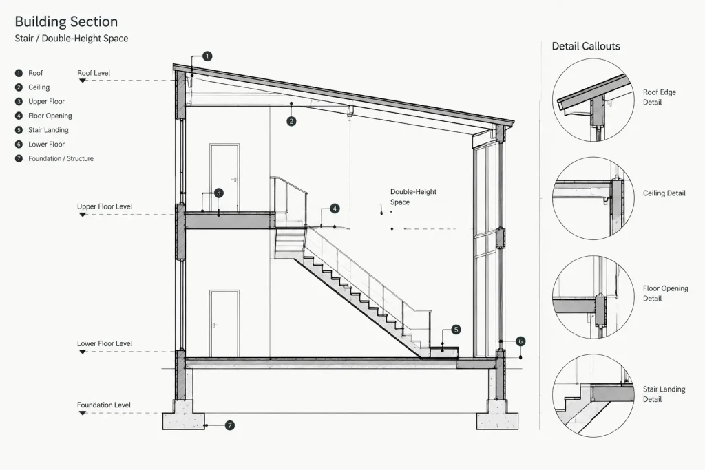
Stairs are common sources of section errors because plans divide their geometry across levels. Confirm landing positions, floor openings, overhead clearance zones, support conditions, and the relationship between the stair and adjacent ceilings. The section should agree with both the lower and upper floor plans.
Openings also require cross-checking. Compare door and window heads, sills, transoms, and mullion divisions with the elevations and schedules. A window may align correctly in plan but conflict vertically with a ceiling, roof edge, casework element, or exterior feature.
For atriums, shafts, double-height rooms, and similar spaces, verify that floor edges and guards are represented consistently on every affected level. Avoid closing a void in section simply because a floor plan background contains linework across the area.
Add Dimensions and Annotation After Geometry Stabilizes
Premature annotation increases rework. Establish the coordinated section geometry first, then add information in a consistent order. Common annotations include:
- Level datums and elevation markers
- Floor-to-floor and major vertical dimensions
- Overall building heights where required by the drawing purpose
- Ceiling and soffit references
- Room or space labels when they aid orientation
- Grid bubbles aligned with the project grid
- Wall-section and detail callouts
- Material or assembly references appropriate to the drawing scale
Do not duplicate the same information unnecessarily. If a datum already communicates a floor elevation, an additional dimension may add clutter without improving coordination. Place notes in open areas and keep leaders from crossing critical geometry.
Organize the CAD File for Revision
Building sections change as plans and elevations develop, so editable organization matters. Separate cut geometry, beyond geometry, hatches, datums, grids, annotation, and temporary construction lines according to the project layer system. Apply object properties consistently rather than correcting plotted appearance with scattered overrides.
Use referenced plans and consultant backgrounds in a controlled manner. Their display should support projection and checking without dominating the finished section. Freeze, fade, or clip reference information as appropriate to the working view, but retain a method for reviewing the full coordinated context.
Quality-Control Checklist
Before issuing the drawing, review the building section against the plans, elevations, roof information, and relevant details. A focused check should confirm:
- The plan cut line, viewing direction, title, and section reference agree.
- Grid lines and level datums match the coordinated drawing set.
- Walls, slabs, roofs, openings, and stairs occur where the source plans indicate.
- Elements at the cut plane are visually stronger than elements beyond.
- Floor edges and voids remain consistent across adjacent levels.
- Door and window positions agree with elevations and schedules.
- Ceilings, soffits, shafts, and major service zones do not create obvious conflicts.
- Grade relationships agree with the current site information.
- Detail callouts point to conditions actually shown in the referenced views.
- Temporary projection geometry and non-plotting notes are not visible in the sheet output.
- Text, hatches, lineweights, and linetypes remain readable at the plotted scale.
A final visual review is also valuable. Temporarily hide annotation and inspect the architectural geometry by itself. Then restore annotation and review the sheet at its intended output size. This separates geometric problems from graphic congestion.
Treat the Section as a Coordination View
A strong building section is more than a presentation drawing. It is a test of whether the floor plans, roof, elevations, levels, structure, ceilings, and site relationships describe the same building. Drafting the section may reveal conflicts that are difficult to notice in isolated plan views.
Choose the cut deliberately, project from current sources, distinguish cut from background, and annotate only after the geometry is stable. With that workflow, building sections in architectural CAD become easier to revise, clearer to read, and more useful throughout design and documentation.
A Practical Method for Reviewing Section Revisions
When a plan, elevation, roof condition, or consultant background changes, review the section by source rather than editing isolated lines from memory. Identify which elements depend on the revised information, update the controlling geometry, and then inspect connected conditions such as ceilings, openings, stairs, wall tops, and detail references.
It is useful to distinguish between a genuine coordination conflict and a graphic inconsistency. A coordination conflict means related views describe different physical conditions. A graphic inconsistency occurs when the geometry agrees but lineweight, hatch, linetype, annotation, or background emphasis makes the section misleading. These problems require different corrections.
Questions to Ask During a Redline Review
- Does the section cut still pass through the conditions shown by the plan marker?
- Are vertical positions controlled by current project datums rather than visual alignment?
- Can the reader distinguish cut construction from objects seen beyond?
- Do openings agree with the plans, elevations, and available schedules?
- Are voids, shafts, stairs, and floor edges coordinated across the affected levels?
- Do section and detail references point to the intended conditions?
- Has temporary projection geometry been separated from printable linework?
After corrections, compare the section with its source views again instead of assuming that the redline resolved every related condition. This final cross-check helps prevent a local edit from creating a new inconsistency elsewhere in the drawing set.
Maintain Traceable Drawing Logic
A well-organized section should make its drafting logic understandable to another CAD user. Consistent layers, restrained overrides, clear reference management, and recognizable datums allow future revisions to be completed without reconstructing how the view was developed.
Where a condition remains unresolved, avoid using detailed graphics that imply a finalized assembly. Show the established design relationship, identify the area requiring further development, and coordinate it with the appropriate enlarged view or project detail.
Frequently Asked Questions
What is the main purpose of a building section?
A building section communicates vertical and spatial relationships across a significant part of a building. It helps coordinate floors, roofs, openings, stairs, ceilings, grade, and other elements that cannot be fully understood from plans alone.
How is a building section different from a wall section?
A building section explains the broader organization of the building. A wall section focuses on a limited enclosure condition and typically develops assembly layers, transitions, and connections in greater detail.
Should every line from the floor plan appear in the section?
No. Plan geometry should be evaluated according to whether it is cut, visible beyond the cut, hidden but necessary, or irrelevant to the section. Copying every plan line usually reduces clarity.
Why should annotation be added after the geometry is coordinated?
Levels, dimensions, tags, and callouts depend on stable geometry. Adding them too early creates unnecessary rework and can leave outdated information after the building elements change.
How should cut elements differ from background elements?
Elements intersected by the cut plane should receive the strongest graphic emphasis. Visible elements beyond should be progressively subordinate so the viewer can understand depth and the location of the cut.
What drawings should be checked against a building section?
Review the section against current floor plans, roof information, elevations, relevant schedules, site information, consultant backgrounds, and applicable enlarged details. The exact sources depend on the project and the conditions crossed by the cut.
Can a building section be used as a construction detail?
A building section can show major assembly relationships, but it should not be overloaded with information better communicated in wall sections or enlarged details. Use referenced views when a condition requires more focused development.