Drafting access panels in architectural CAD requires more than placing a rectangular symbol on a wall or ceiling. Each opening must connect a concealed service requirement with a usable access route, a coordinated architectural surface, and consistent documentation.
This guide explains how to represent access panels clearly, coordinate them with consultant backgrounds and finish layouts, and keep plans, reflected ceiling plans, elevations, details, and schedules aligned as locations change.
Access panels are easy to overlook because they are usually driven by equipment concealed behind walls or above ceilings. A panel may appear minor on an architectural drawing, but its position can affect finish layouts, ceiling grids, millwork, signage, lighting, and the ability to service building systems.
A reliable CAD workflow treats an access panel as a coordinated architectural element rather than a symbol added near the end of documentation. Its required location should be established with the relevant consultant, checked against visible finishes, and represented consistently in every affected drawing.
Begin with the service requirement
Before drawing a panel, identify what must be reached and why. The required access may relate to a valve, damper, control, junction point, cleanout, concealed connection, or other maintainable component. Architectural drawings should not guess at this requirement when it originates in another discipline.
Review the latest consultant backgrounds and record enough information to coordinate each condition:
- The concealed item requiring access
- The discipline responsible for confirming its location
- Whether access is needed from a wall, ceiling, floor, cabinet, or other assembly
- The preferred direction of approach
- Known obstructions between the room surface and the concealed item
- Finish, appearance, security, moisture, or fire-resistance considerations requiring verification
The opening should provide a practical route to the service point. Placing a panel symbol directly beneath or beside a consultant symbol does not automatically establish workable access. Framing, ducts, pipes, insulation, light fixtures, casework, and equipment can block the path.
Choose the drawing view that best communicates the panel
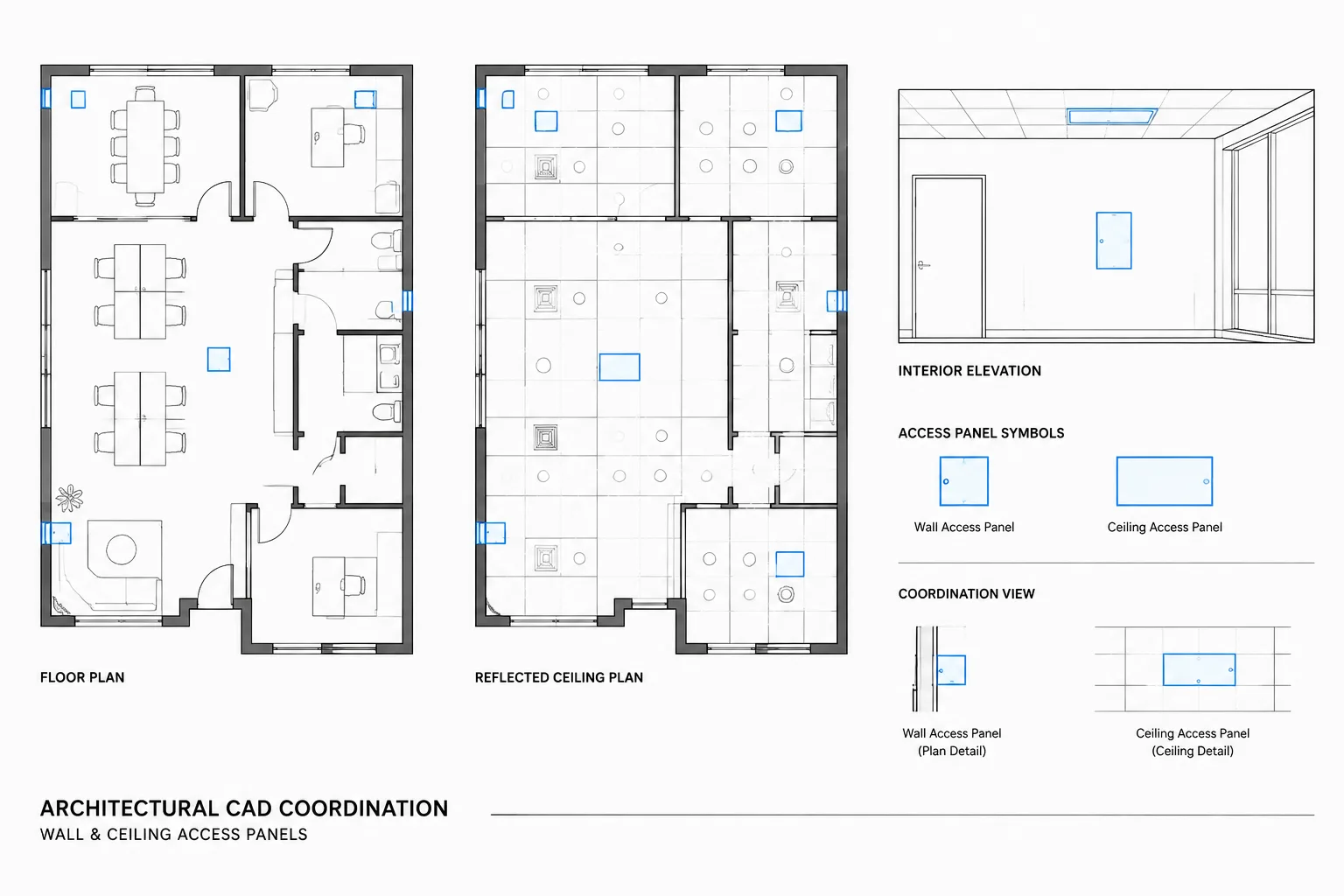
An access panel should be shown where its location can be understood and coordinated. The appropriate view depends on the host surface and the importance of its appearance.
| Drawing view | Typical use | Primary coordination question |
|---|---|---|
| Floor plan | Wall-mounted panels and panels associated with room layout | Does the panel conflict with doors, furniture, equipment, or casework? |
| Reflected ceiling plan | Panels located in gypsum board, tile, or other ceiling systems | Does the panel align with the ceiling layout and avoid fixtures? |
| Interior elevation | Visible wall panels or panels within finish compositions | How does the panel relate to joints, tile, millwork, and mounted items? |
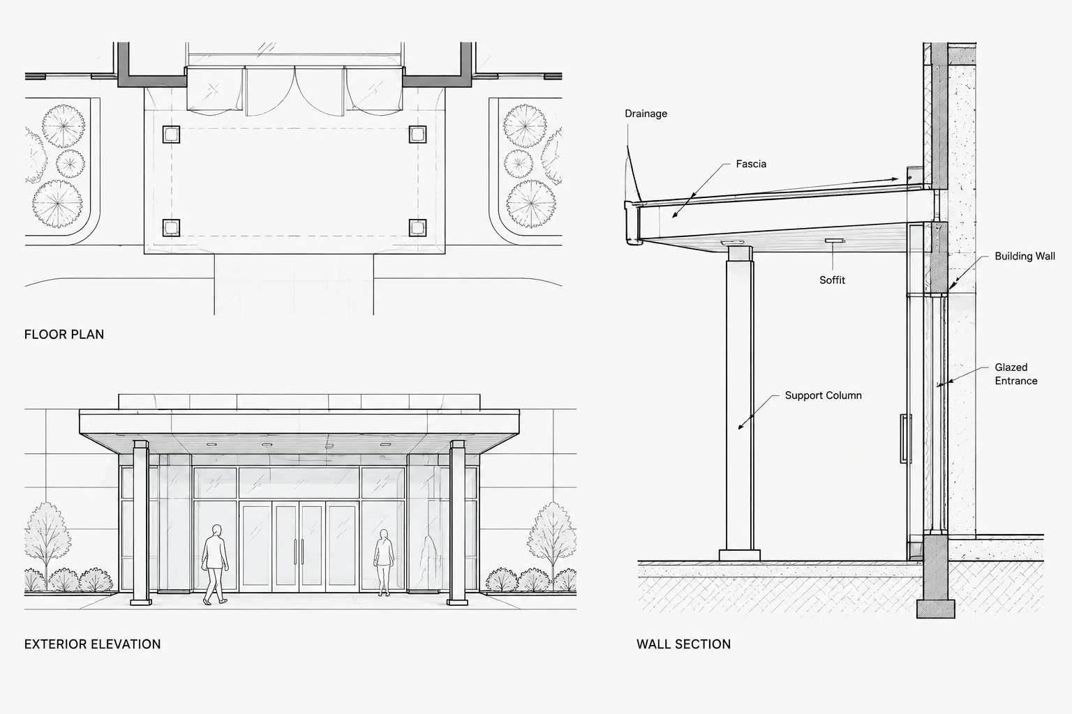
| Building section or wall section | Conditions where depth and access direction are important | Is there a clear route through the assembly to the service point? |
| Enlarged plan or detail | Congested or unusual conditions | Can the opening, frame, surrounding construction, and clearance be explained clearly? |
A panel does not need to appear in every possible view. Show it in the views required to locate, build, and coordinate it. When it appears more than once, use a common identifier so that the representations do not become disconnected.
Build a simple, adaptable CAD symbol
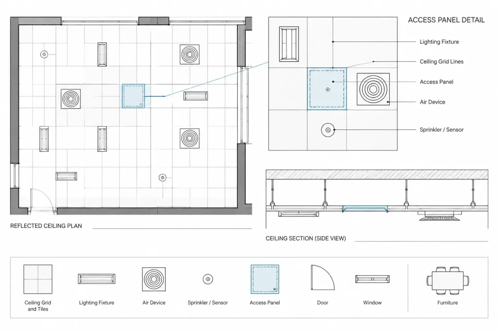
An access panel block should remain legible at the intended plot scale without pretending to show unverified product details. A practical symbol may include an opening outline, a minimal frame indication, an optional swing or access-direction graphic, and an attribute for the panel identifier.
Keep the symbol separate from surrounding wall, ceiling, or finish geometry. This makes it easier to move the panel during coordination and reduces the chance of leaving behind partial linework. Avoid placing project-specific notes, finish patterns, or fixed dimensions inside a general library block.
Use a meaningful insertion point
Select an insertion point that supports placement and checking. A center point is convenient for aligning a ceiling panel with a grid or bay. A corner point may be more useful when the opening is dimensioned from adjacent construction. Whichever method is chosen, apply it consistently across the project library.
Separate symbol graphics from annotation
Place panel outlines, identifiers, dimensions, and detail callouts on the appropriate project layers. This allows the graphics to be controlled independently in floor plans, reflected ceiling plans, elevations, and enlarged views. It also prevents annotation from rotating or scaling unexpectedly when the block is reused.
Coordinate ceiling access panels with the reflected ceiling plan
Ceiling panels often compete with lights, diffusers, sprinklers, detectors, speakers, curtain tracks, ceiling joints, and decorative features. Begin with the current architectural ceiling layout and overlay the relevant consultant backgrounds. Do not coordinate against an isolated mechanical or electrical plan without the architectural ceiling geometry visible.
Check each proposed panel for:
- A clear opening area within the ceiling composition
- Conflicts with ceiling-mounted devices and their visible trim
- Interference from concealed framing or service runs
- Compatibility with tile modules, linear systems, or control joints
- A usable route from the panel to the item being serviced
- Visual alignment in prominent rooms
In a modular ceiling, the ceiling system itself may provide a form of access, but that should not be assumed for every location. The route may still be obstructed above the ceiling, or the system may include fixed components. Confirm the intended access strategy with the project team.
Coordinate wall panels with finishes and room elements
Wall access panels can be visually prominent and are frequently affected by elements that are not obvious on a consultant plan. Review floor plans and interior elevations together. A location that appears open in plan may conflict with a mirror, wall protection, artwork, tile pattern, shelving, plumbing fixture, door swing, or built-in cabinet when viewed in elevation.
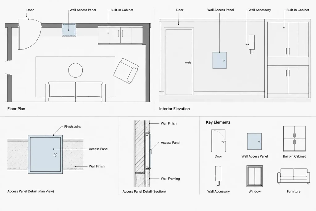
Where possible, coordinate the opening with the finish composition rather than allowing it to interrupt the layout arbitrarily. This may involve aligning edges with joints or locating the panel in a less prominent surface. Such adjustments must still preserve functional access to the concealed component.
Panels within millwork require particular care. Determine whether the access is through a removable cabinet component, an architectural panel, or a separate manufactured opening. Show which trade or drawing scope defines the visible surface and how the service route continues behind it.
Tag panels without overloading the drawing
A short identifier can connect the graphic to a schedule, note, or detail. The identifier should remain stable as the panel moves. Avoid embedding uncertain size, material, or performance information in the tag unless that information has been verified and is being managed consistently.
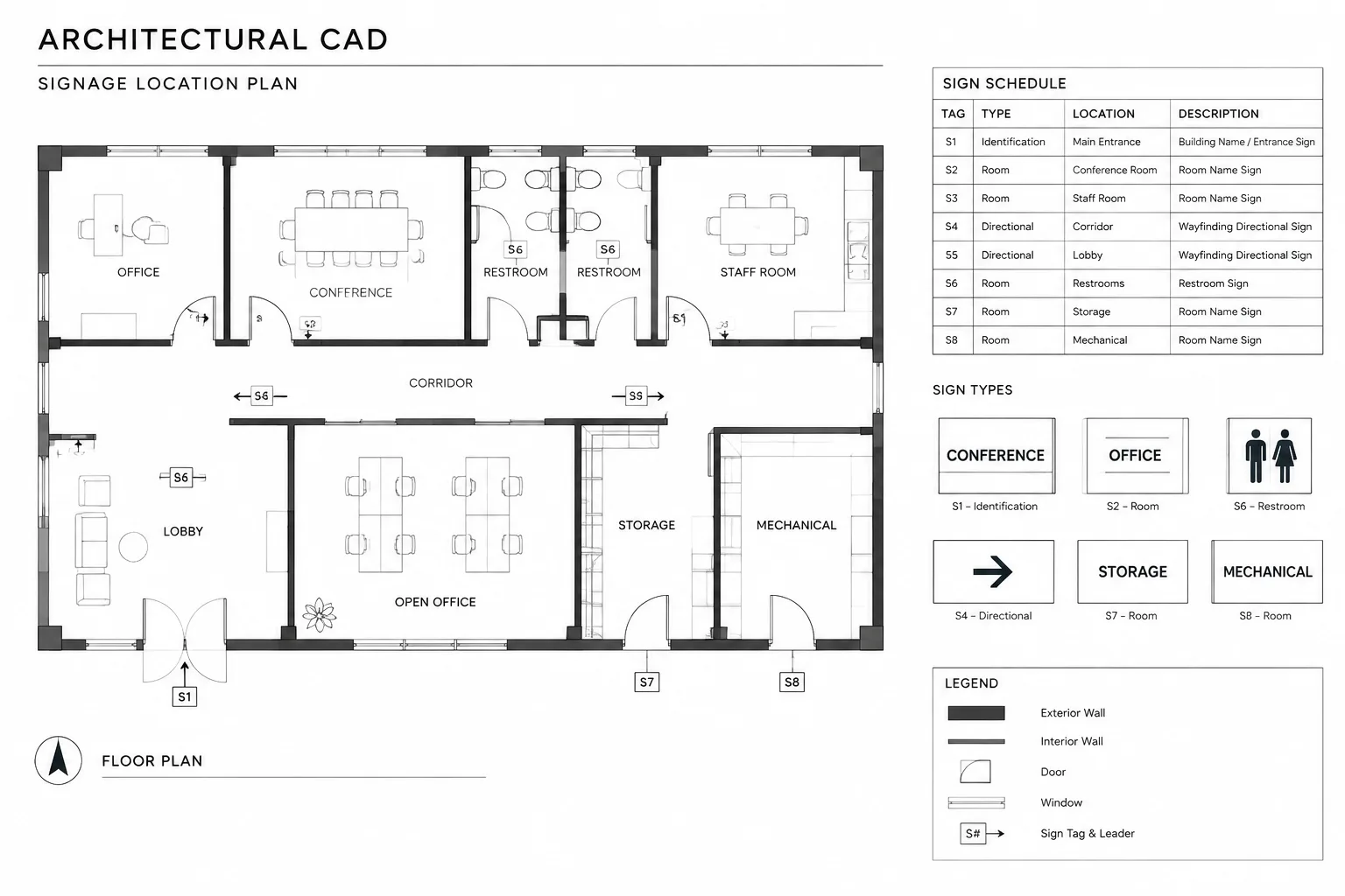
A project may distinguish panels by host condition, type, or location. Whatever system is selected, define it in a legend or schedule and avoid using several unrelated naming methods. If a generic note is sufficient for a simple project, confirm that it still allows each critical panel to be found and coordinated.
Useful schedule fields
When several panels are involved, a schedule can reduce repeated notes. Potential fields include:
- Panel identifier
- Room or area
- Host surface
- Associated system or service item
- Finish requirement
- Reference detail
- Responsible coordination discipline
- Comments or verification status
Only include fields the team will maintain. An elaborate schedule that is not updated is less useful than a concise, coordinated record.
Use overlays to resolve multidisciplinary conflicts
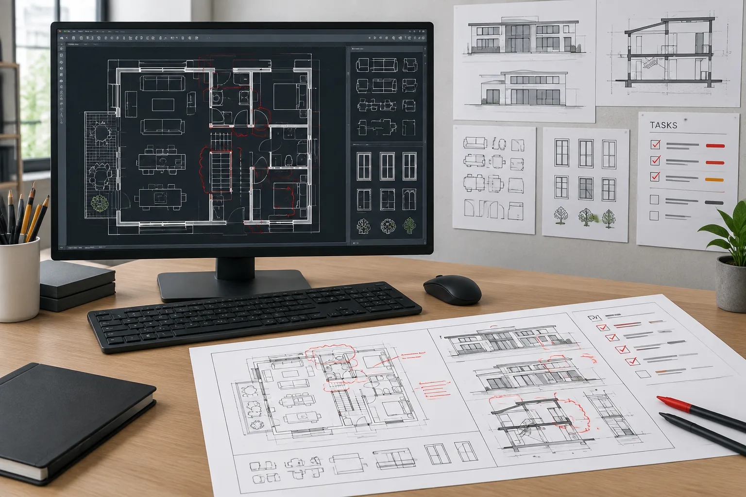
Create a coordination view that combines the architectural plan or reflected ceiling plan with current structural, mechanical, electrical, plumbing, and fire-protection backgrounds as applicable. Use subdued display settings for reference files so that access panel graphics and conflict areas remain easy to read.
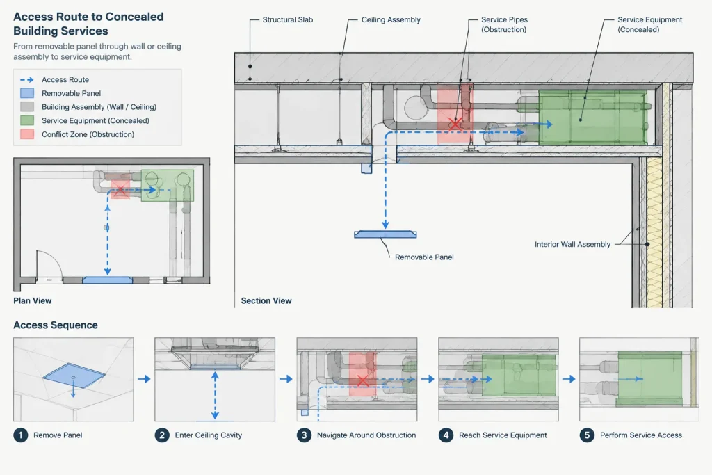
For each panel, trace the entire access path rather than checking only the surface opening. A section or quick diagram may reveal that the concealed target sits beyond another system. If the route is unclear, flag the location for consultant review instead of resolving it by assumption.
Keep issue markers, review clouds, and temporary notes on dedicated coordination layers. Once a decision is confirmed, update the actual panel location and remove obsolete markup so that unresolved comments are not mistaken for current design information.
Verify related drawings after every relocation
Access panels commonly move as consultant layouts develop. A change made in the reflected ceiling plan may also affect an interior elevation, detail, finish plan, schedule, or consultant background. Use the panel identifier to search the drawing set and check every representation after a relocation.
A focused quality-control pass should confirm that:
- The architectural location agrees with the latest coordinated service point
- The panel appears in the correct plan, ceiling plan, or elevation
- Tags are unique and match any schedule
- Dimensions locate the opening from stable references
- No light, diffuser, mounted accessory, millwork component, or door operation conflicts with it
- Referenced details represent the actual host condition
- Temporary options and superseded panel symbols have been removed
- Performance and finish requirements have been verified rather than assumed
Treat access as a design constraint
The best time to coordinate an access panel is while concealed systems, ceilings, walls, and room layouts can still be adjusted together. Late placement often produces awkward finish interruptions or openings that do not provide useful access.
In CAD, the key is not drawing a more detailed rectangle. It is maintaining a clear relationship among the service requirement, accessible route, architectural surface, consultant information, and drawing-set references. A simple, consistently tagged symbol supported by disciplined overlays and verification can prevent a small opening from becoming a large coordination problem.
A practical access-panel coordination sequence
A repeatable review sequence helps separate confirmed requirements from provisional locations. Begin with the concealed component, identify the intended approach, examine the construction between the finished surface and the service point, and then test the proposed opening against architectural and consultant information.
- Confirm the need: Record which component requires service and which discipline must verify it.
- Trace the route: Check the full path from the room-facing opening to the concealed component.
- Review the host: Identify the wall, ceiling, cabinet, or other assembly receiving the opening.
- Test visible coordination: Compare the panel with finish joints, ceiling patterns, fixtures, casework, signs, and mounted accessories.
- Document consistently: Use a stable identifier and show the panel only in the views needed to locate and explain it.
- Close the issue: Replace temporary markup with confirmed drawing information and remove superseded graphics.
Manage uncertainty without hiding it
During design development, some panel locations may remain dependent on consultant confirmation or field conditions. Do not convert an unresolved assumption into finished-looking construction information. Use clearly controlled coordination notes or status fields so reviewers can distinguish a proposed position from a verified one.
When a decision is confirmed, update the actual drawing geometry, annotation, references, and schedule entry together. This prevents temporary comments from becoming a parallel source of information that conflicts with the issued drawings.
Coordinate the drawing, not just the symbol
A well-made CAD block improves consistency, but it cannot establish whether access is physically possible. Effective documentation combines simple graphics with disciplined file coordination, clear responsibility, and review across every affected view. The final check should ask whether a person can identify the opening, understand what it serves, and follow a plausible service route without relying on an unrecorded assumption.
Frequently asked questions
Should an access panel appear on the floor plan or reflected ceiling plan?
Show it in the view that best locates the host surface and communicates relevant conflicts. Wall panels commonly require plan or elevation coordination, while ceiling panels are generally coordinated in the reflected ceiling plan. Congested conditions may also need a section, enlarged view, or detail.
What should an access-panel CAD block contain?
Use only the graphics needed for clear placement and recognition, such as the opening outline, a restrained frame indication, an optional access-direction graphic, and an identifier attribute. Keep project-specific dimensions, finishes, and unverified performance information outside a general library block.
Can the panel be placed directly beside the consultant symbol?
Not without checking the complete access path. The apparent proximity of symbols does not account for framing, ducts, piping, insulation, equipment, or other concealed obstructions between the opening and the service point.
How should access panels be coordinated with ceiling grids and finishes?
Overlay current consultant information on the architectural ceiling or finish layout. Check visible alignment, joints, fixtures, trim, concealed obstructions, and the route to the service item. Appearance should be coordinated without compromising functional access.
When is an access-panel schedule useful?
A schedule is helpful when several panels must be tracked across rooms, host conditions, service systems, finishes, details, and responsible disciplines. Include only fields the team can maintain reliably.
What should be checked when an access panel moves?
Review every related plan, reflected ceiling plan, elevation, detail, finish drawing, schedule, and consultant reference. Confirm that the identifier remains consistent and remove obsolete symbols or temporary coordination notes.