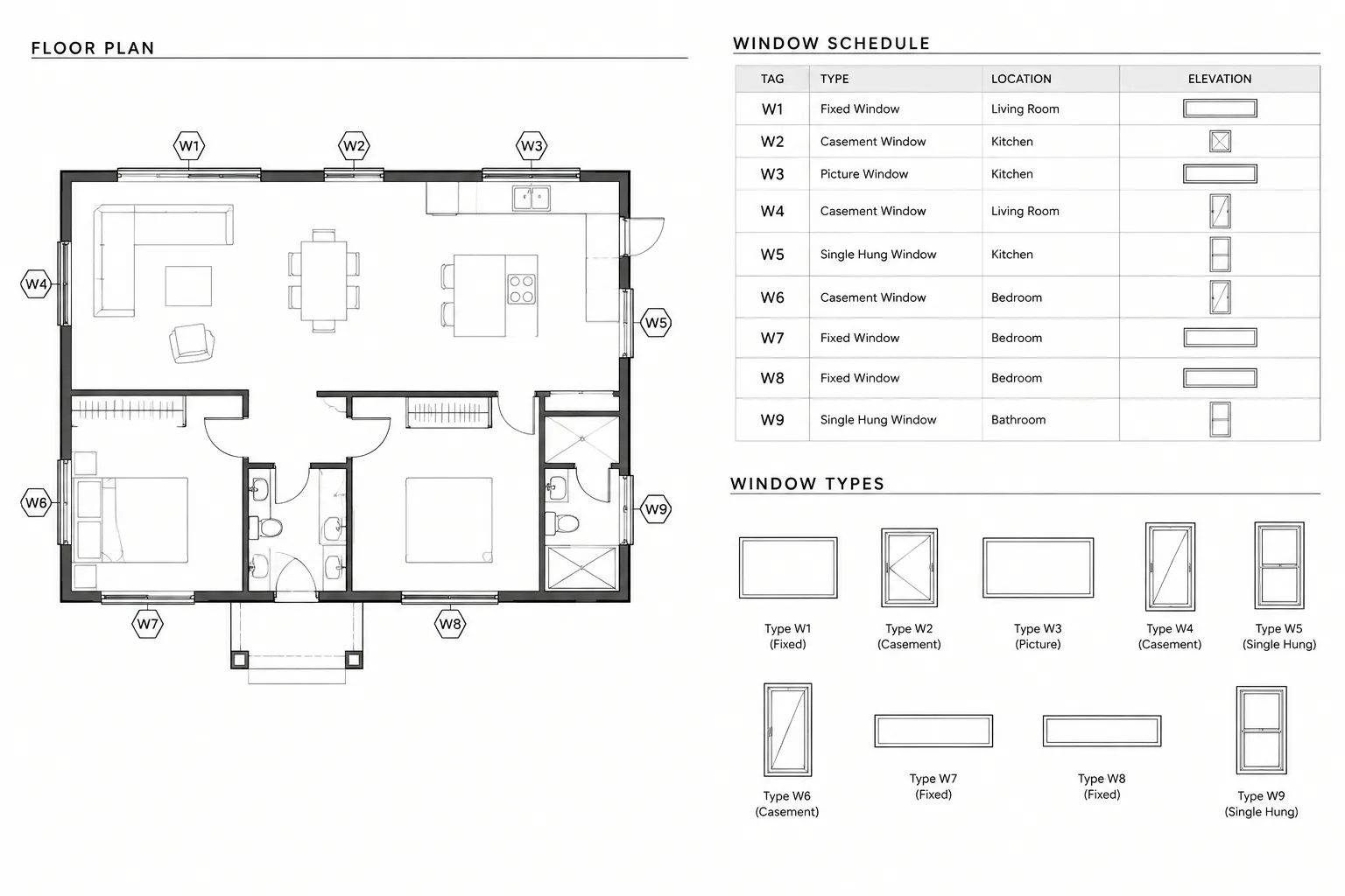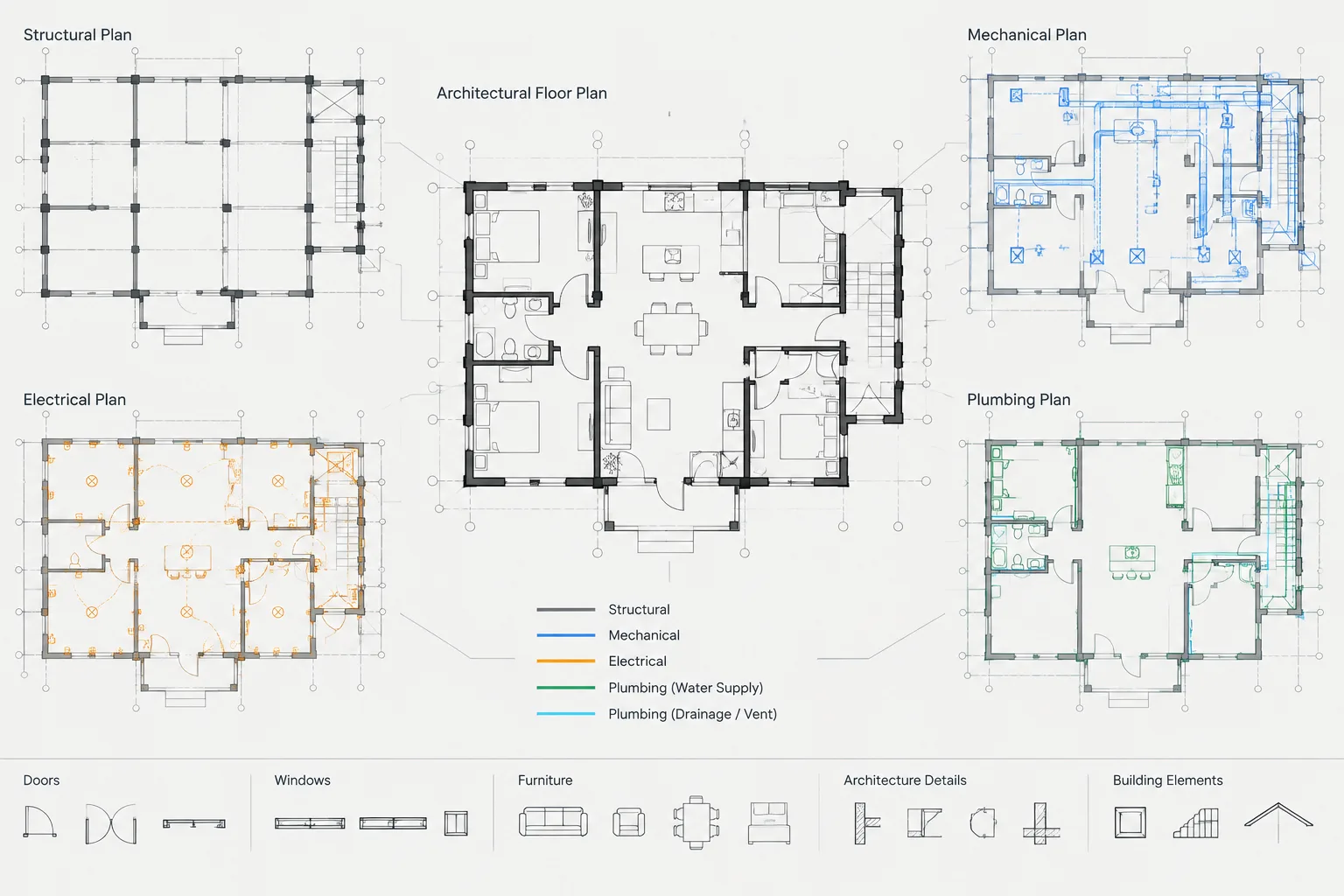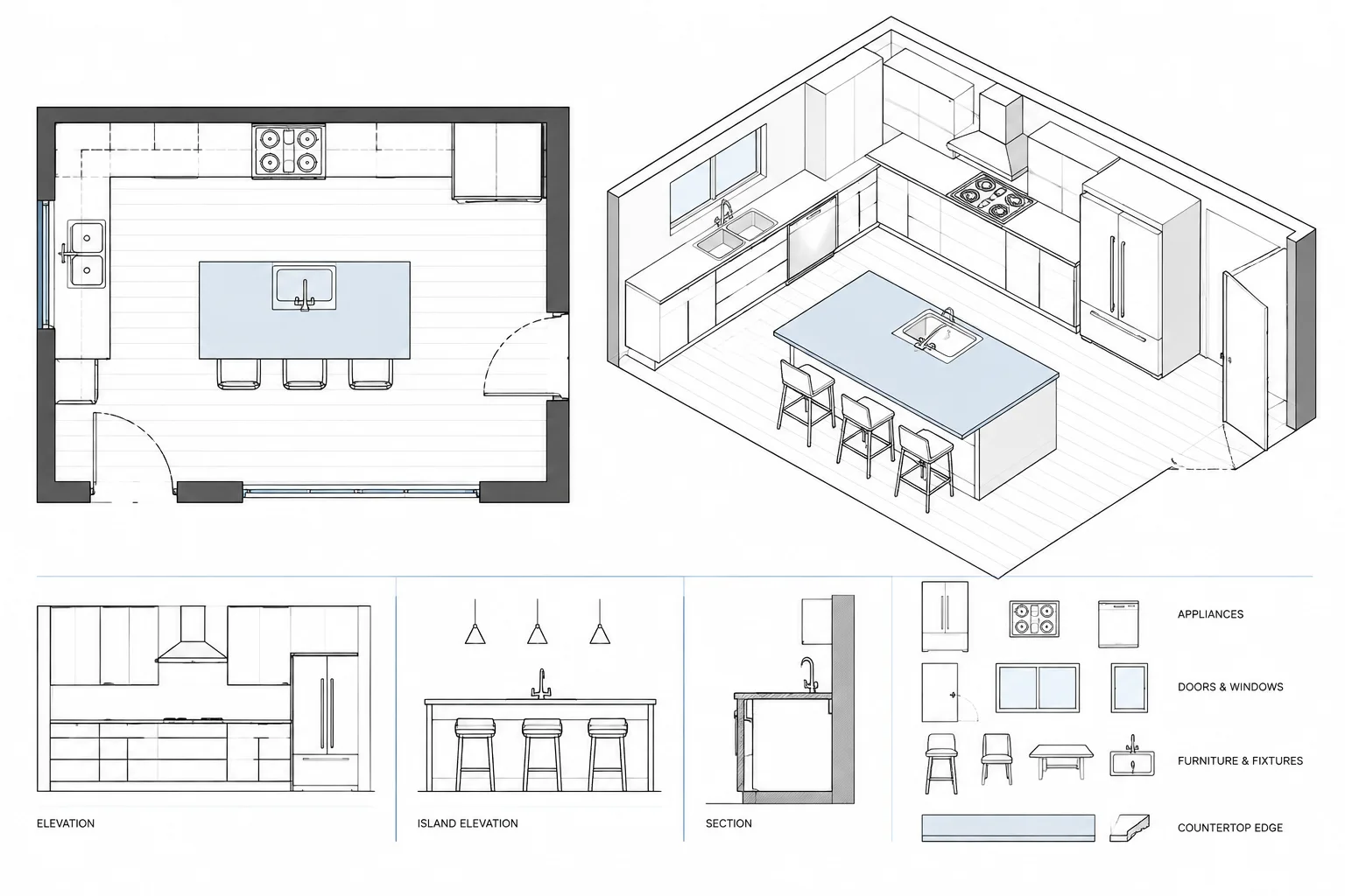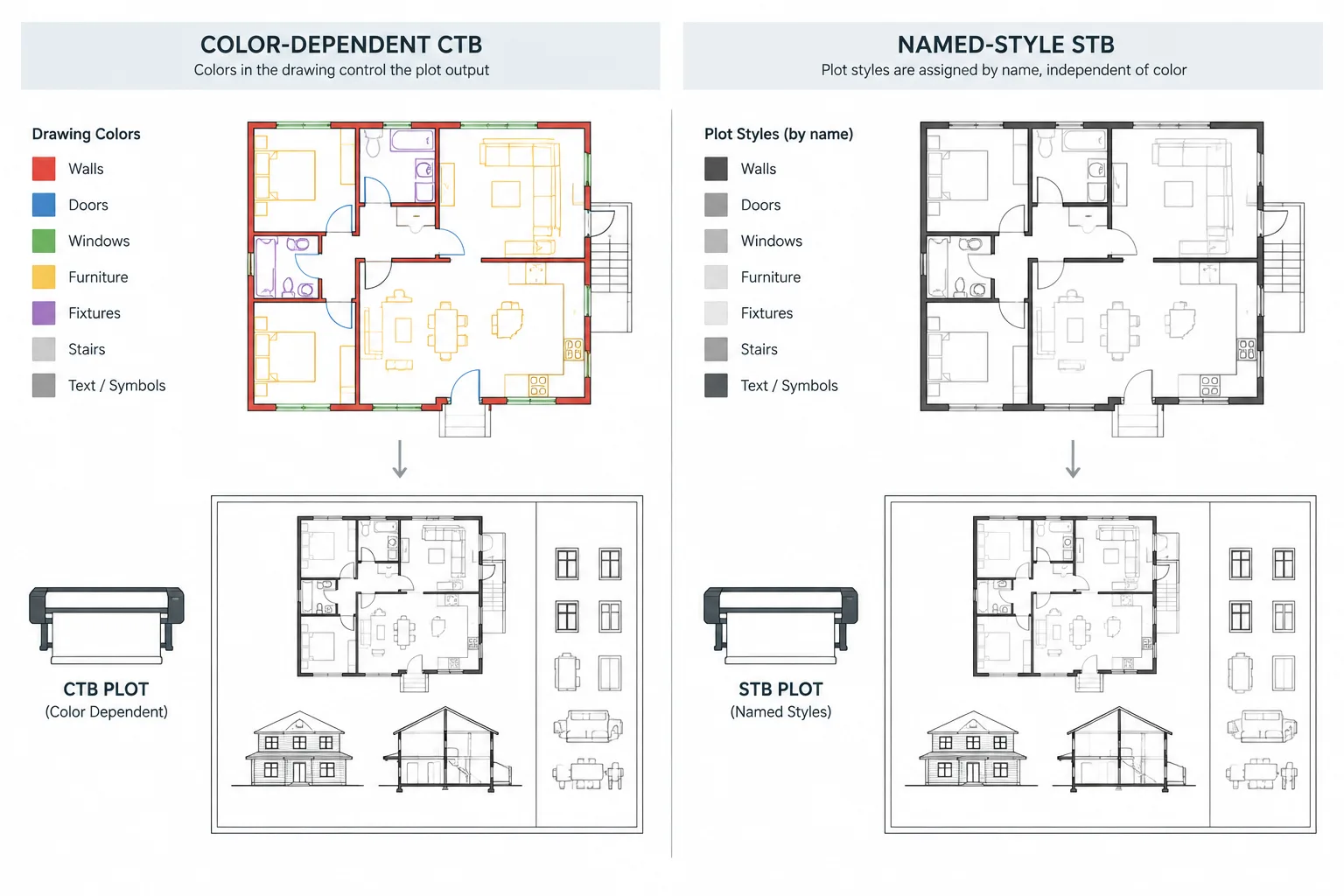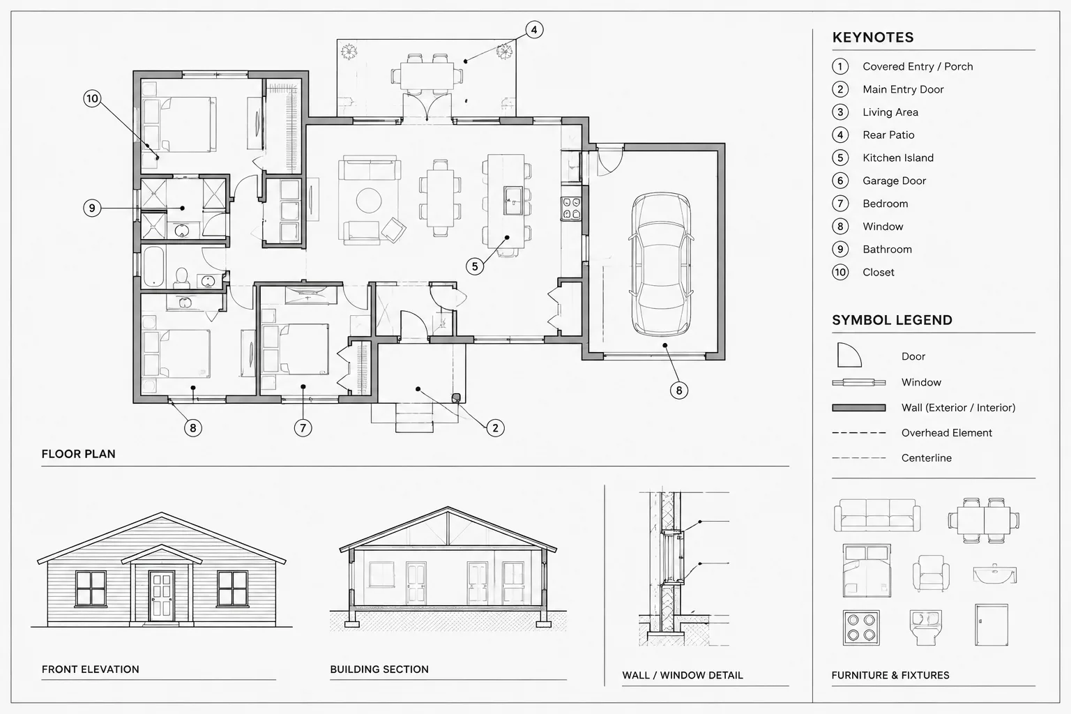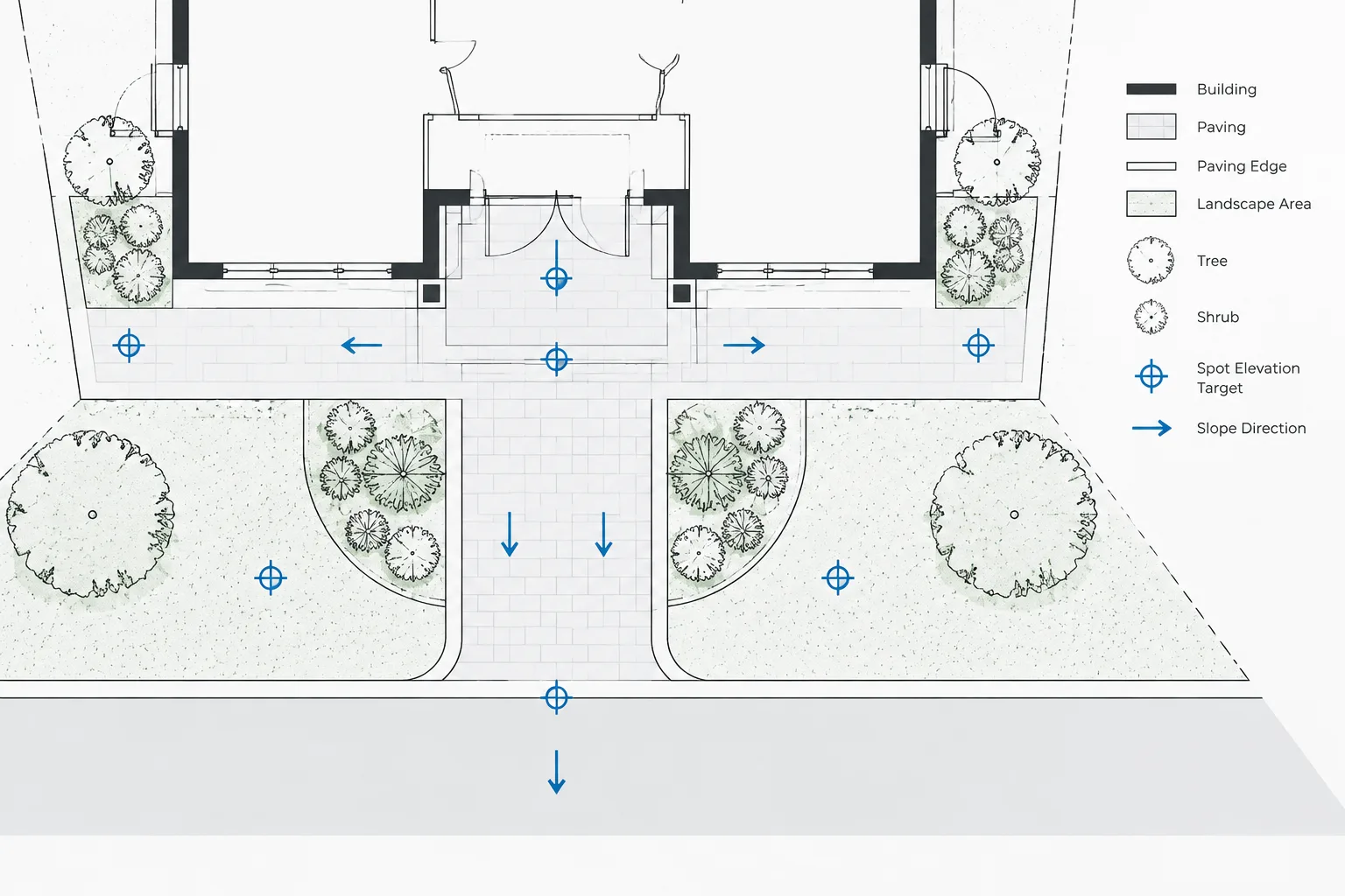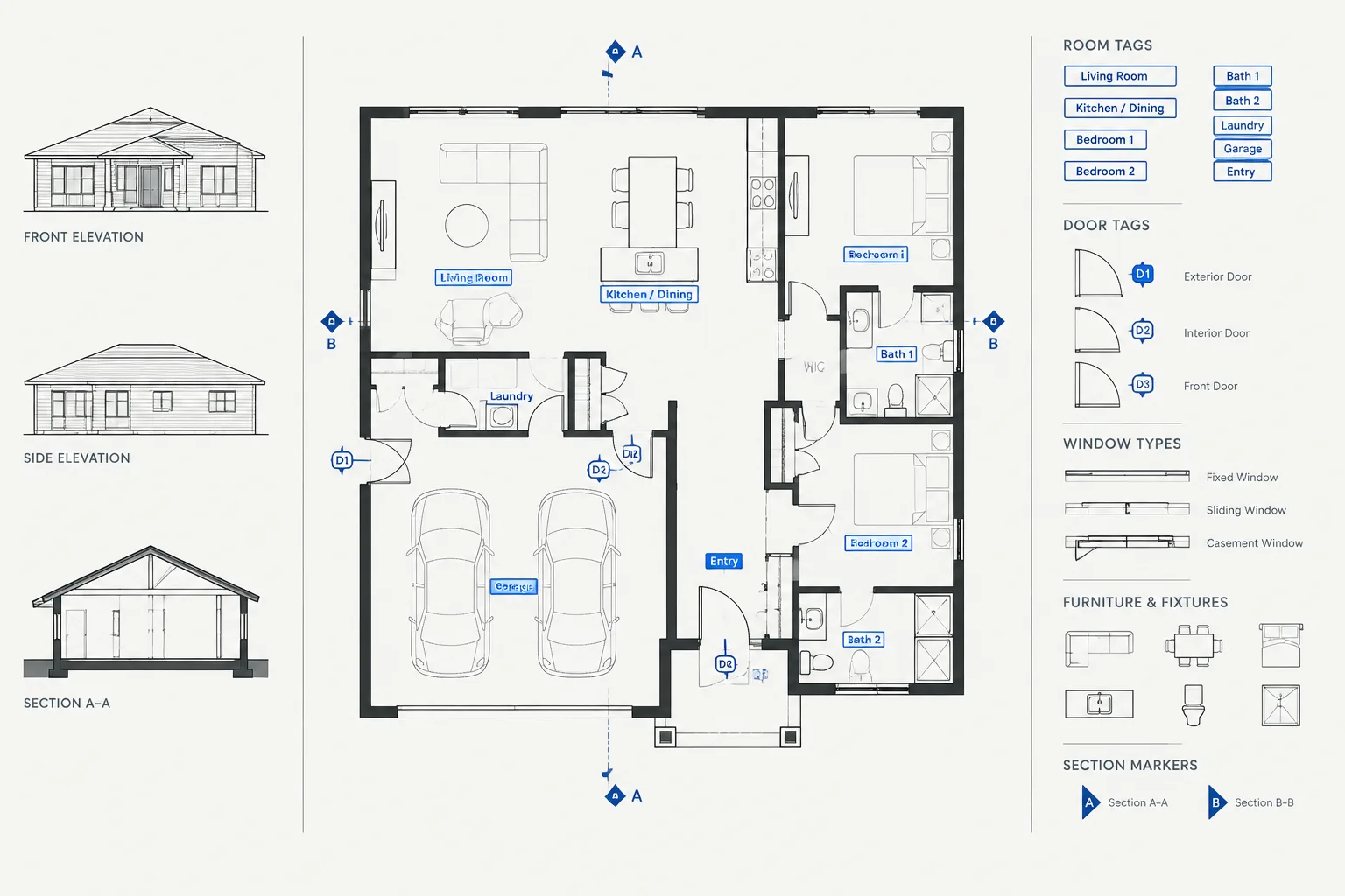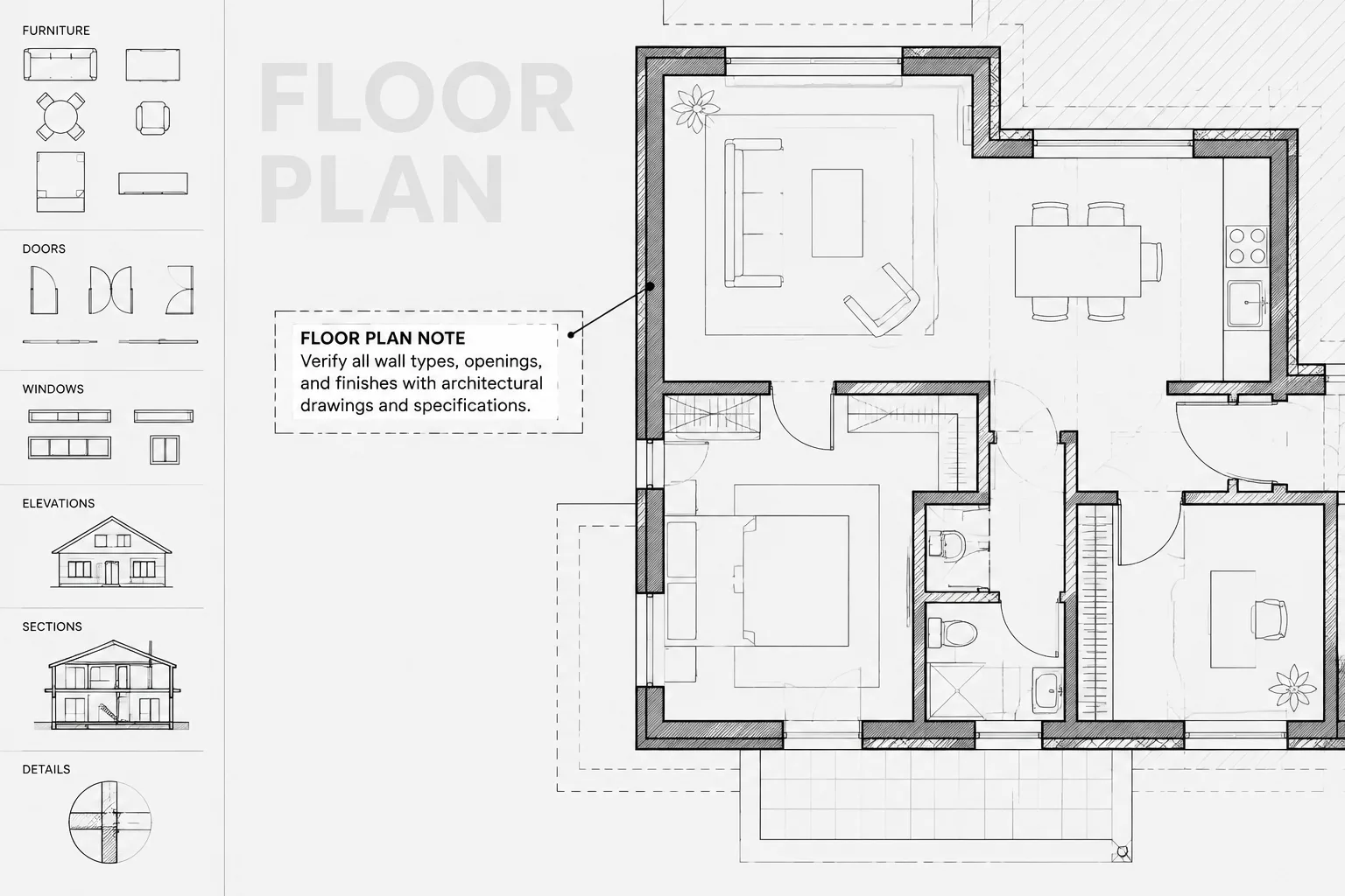
Architectural CAD wipeouts and background masks can clarify notes, labels, and symbols placed over dense linework. Their effectiveness depends on more than creating an opaque area: the boundary, object stacking, layer organization, and plotted output must work together.
This guide explains how to select an appropriate masking method, control draw order, coordinate masks with blocks and external references, and identify situations where correcting the drawing is better than concealing it.
Dense architectural drawings often place notes, room names, dimensions, symbols, and detail references over walls, hatches, furniture, or consultant backgrounds. When those elements compete visually, a small area of masking can make the annotation readable. Used carelessly, however, the same mask can hide geometry, create plotting surprises, or make a DWG difficult to edit.
Architectural CAD wipeouts and background masks should be treated as graphic tools rather than substitutes for drawing cleanup. The goal is not to erase inconvenient information. It is to create controlled visual separation while preserving the underlying project geometry.
Understand the Three Parts of the Workflow
Clear masking depends on three related controls:
- Mask geometry: The boundary that covers objects behind it.
- Draw order: The stacking relationship between the mask, annotation, hatches, references, and other objects.
- Frame display: Whether the edge of a wipeout is visible during editing and whether it appears in plotted output.
A typical stack places the building geometry at the back, a tightly fitted mask above it, and the note or symbol at the front. If any part of that order changes, text may disappear or background lines may show through.
Choose the Least Complicated Masking Method
Not every crowded annotation needs a wipeout. Start with the simplest method that solves the graphic problem.
| Method | Best use | Main caution |
|---|---|---|
| Repositioning annotation | Notes, dimensions, or tags that can move into open space | Maintain a clear relationship between the annotation and referenced object |
| Mtext background mask | Paragraph notes, room labels, and text placed over linework | Check the mask margin and text behavior at the plotted scale |
| Block-based mask | Repeated symbols or tags that consistently need a clear field | Test insertion, rotation, scaling, and nesting behavior |
| Wipeout object | Irregular areas or symbols requiring a custom masking boundary | Large wipeouts can conceal important geometry and complicate selection |
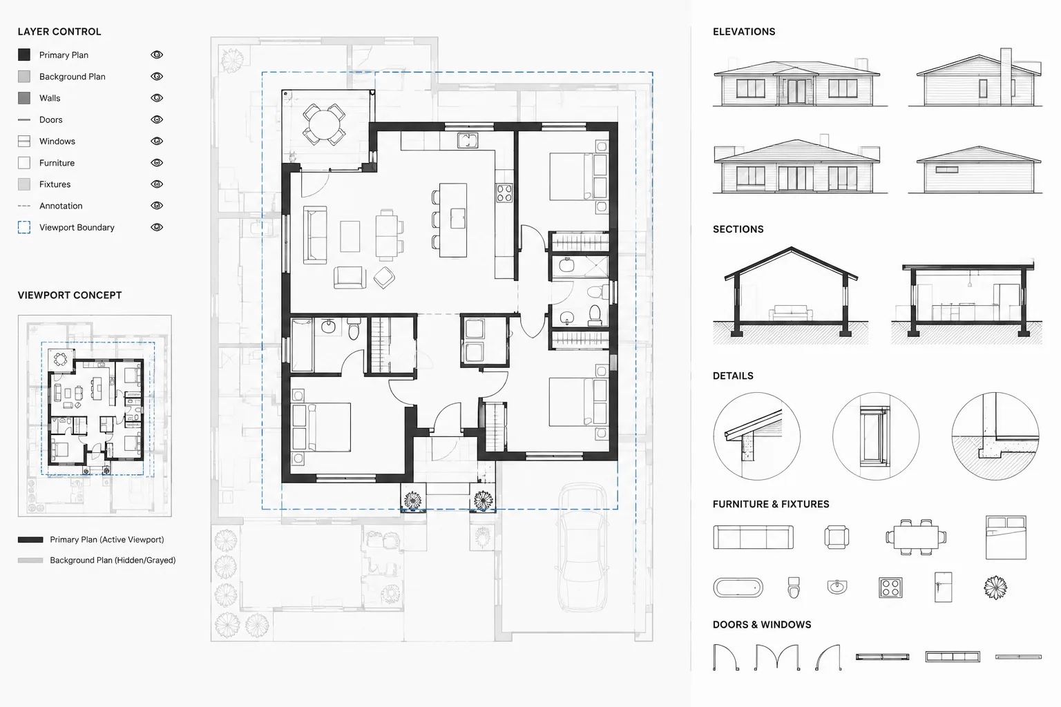
| Viewport or layer control | Background information that should not appear in a particular view | Do not alter shared model information when the change belongs only to one sheet |
Moving a note is often better than placing a large opaque shape beneath it. Layer or viewport control may also be more appropriate when an entire category of information is unnecessary in a view.
Use Text Background Masks for Local Readability
An Mtext background mask is usually the cleanest choice when the problem is limited to text. Because the mask belongs to the text object, it moves and edits with the annotation. This reduces the risk of leaving a separate wipeout behind after a note is relocated.
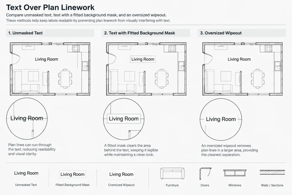
Fit the mask closely enough to avoid removing nearby context, but leave enough separation that lines do not visually touch the characters. Review the result in a layout at the intended plotting scale. A mask that looks restrained while zoomed in can appear oversized on a printed sheet.
Use a consistent office approach for masked text. If some notes have generous opaque fields while others have almost no margin, the drawing can look patched together. Consistency is especially important for room labels, general notes, and repeated callouts.
Create Wipeouts with Deliberate Boundaries
The WIPEOUT command is useful when the masking area is not tied to a single text object. It may be appropriate behind a custom symbol, a keyed note enclosure, or an annotation crossing complex hatchwork.
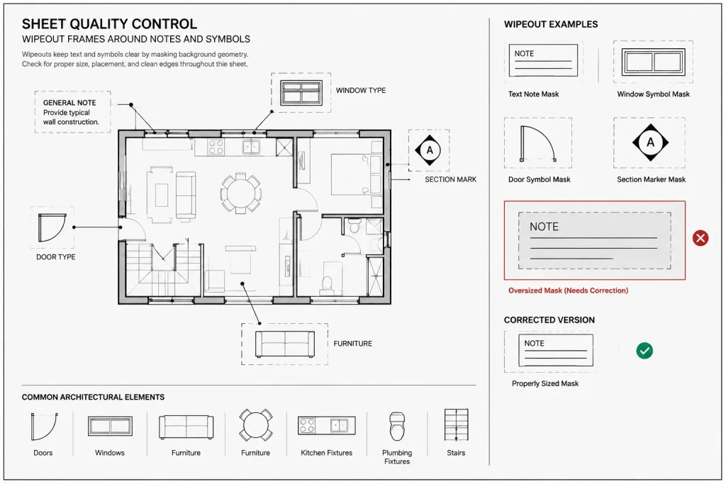
Keep the boundary simple. Excessive vertices make the object harder to grip-edit and can introduce unexpected edges. Avoid broad masks covering large portions of a plan simply to make a small symbol readable. A compact boundary is easier to inspect and less likely to hide unrelated work.
When tracing a closed shape, verify that the boundary follows the intended visible area. Do not assume the source polyline is clean merely because it looks closed. Duplicate segments, self-intersections, or stray vertices can produce unreliable results.
Keep Wipeout Frames Available During Editing
A hidden frame creates a common coordination problem: the wipeout remains active but becomes difficult to select or identify. During production, use a frame-display setting that allows the team to see and edit wipeout boundaries without necessarily printing them. Before issue, confirm the office plotting setup produces the intended result.
Frames are useful quality-control information. They reveal oversized masks, abandoned wipeouts, and boundaries extending into adjacent rooms or details.
Manage Draw Order as Part of the Object
A correct wipeout in the wrong stacking position does not work. Use DRAWORDER to place masks above the information being covered and annotation above the mask. Commands that move text or hatches to the front or back can accelerate cleanup, but they should not replace a deliberate review of the final stack.
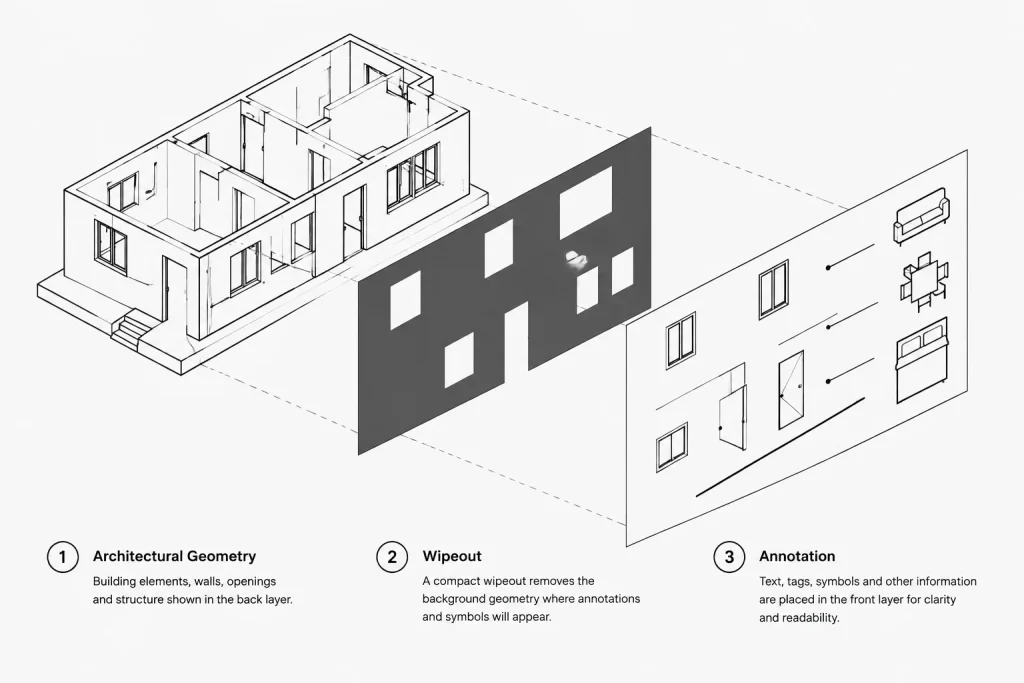
Draw order can become less predictable when content is copied between files, nested inside blocks, or displayed through external references. A mask cannot always be expected to cover geometry located in a different drawing context. Test the actual sheet composition rather than relying only on the source file.
Be Careful with Nested Blocks
A wipeout inside a block may work well for a repeated tag or symbol, but the entire block must be tested. Rotate and mirror representative instances, inspect the mask boundary, and confirm that attributes or other text remain visible. If the block is used in several drawing types, test it against plans, hatches, and screened backgrounds.
Avoid placing a large mask inside a small symbol block. Users may not realize how much information the block conceals after insertion.
Separate Masking from Model Geometry
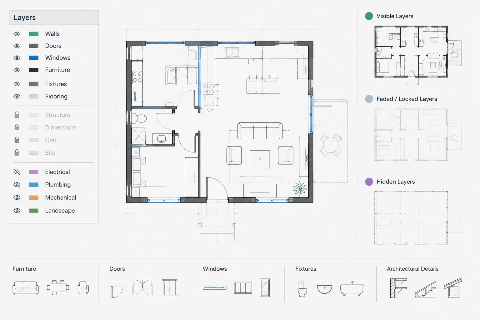
Place wipeouts and masked annotation on purposeful layers that follow the project’s layer strategy. Do not mix them indiscriminately with walls, doors, furniture, or consultant geometry. Clear layer ownership makes it easier to isolate masking objects during troubleshooting.
Whether a mask belongs on an annotation layer or a dedicated masking layer depends on the office workflow. The important point is predictability. A user reviewing a drawing should be able to determine why the object exists, what controls its visibility, and which view depends on it.
Do not use wipeouts to conceal drafting errors such as wall lines extending through openings, overlapping detail components, or hatch boundaries crossing gaps. Correct the underlying geometry whenever the linework itself is wrong.
Coordinate Masks with Xrefs and Hatches
External references often make masking attractive because their linework may be visually dense. Before covering an xref, consider whether layer overrides, clipping, halftone treatment, or a more focused viewport would communicate the view more honestly.
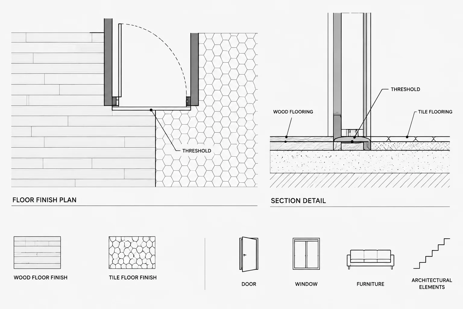
Hatches can also create readability problems. A local text mask may be appropriate over a material pattern, but repeated large wipeouts can fragment the hatch and obscure material continuity. Adjusting hatch display, scale, or layering may produce a cleaner result, provided the change remains appropriate for the entire view.
Check Model Space, Layouts, and Published Output
Masking problems are frequently discovered only after PDF creation. Screen display alone is not a sufficient test. Review the actual layout and publish a test sheet using the project page setup and plot-style workflow.
- Confirm that masked text remains visible and legible.
- Look for wipeout frames that should not print.
- Check whether thin lines unexpectedly show through mask edges.
- Verify that masks do not cover dimensions, door swings, grids, or reference symbols.
- Inspect rasterized or transparency-heavy sheets for display artifacts.
- Compare the PDF with the live layout at representative areas of dense annotation.
If output differs between workstations or publishing methods, inspect page setup, plotting options, reference loading, and object order before redrawing the mask.
Use a Practical Quality-Control Routine
Before issuing a drawing, temporarily display wipeout frames and isolate the relevant annotation layers. Scan the sheet for unexpectedly large boundaries and masks with no visible annotation above them. Then restore the intended display state and review the plotted PDF.
Also test editing behavior. Move a masked note, stretch a nearby wall, and update a representative block. A reliable setup should keep the mask associated with its annotation or make the relationship obvious to the next drafter.
When Not to Use a Mask
A mask is the wrong tool when it changes the apparent design. It should not conceal unresolved wall intersections, clearance conflicts, structural elements, property information, or other geometry that users need to interpret the project. It should also not be used to imitate a revision without updating the underlying drawing.
Good architectural graphics balance clarity with transparency. Use the smallest practical mask, preserve the information needed to understand the view, and verify the final plotted sheet. When wipeouts, background masks, and draw order are managed as a coordinated system, they improve readability without turning the DWG into a collection of hidden problems.
A Diagnostic Approach to Masking Problems
When an annotation does not display as intended, identify the type of failure before rebuilding the mask. If background lines remain visible, inspect the mask boundary and stacking relationship. If the annotation disappears, verify that it is in front of the mask and that its layer remains visible. If the screen and published sheet differ, investigate plotting and reference behavior rather than assuming the geometry is defective.
Review the Drawing Context
- Text-specific conflict: Prefer a mask associated with the text when the obstruction is limited to the label or note.
- Custom symbol conflict: Inspect the symbol, its internal mask, and the order of objects within the block.
- View-wide visual conflict: Consider layer, viewport, hatch, or reference display controls before adding a broad wipeout.
- Incorrect linework: Repair the model or detail instead of covering the error.
- Output-only conflict: Compare the layout and published result using the established project plotting workflow.
Make Masks Understandable to Other CAD Users
A well-managed mask should communicate its purpose during editing. Its layer should be recognizable, its boundary should remain practical to inspect, and its relationship to the annotation should be apparent. This reduces the chance that another drafter will move a note while leaving an unrelated opaque object behind.
During drawing cleanup, look for masks that no longer support visible content. Orphaned wipeouts can survive revisions and conceal new work added later. Removing obsolete masking objects is therefore part of drawing maintenance, not merely graphic refinement.
Evaluate Readability Without Losing Context
The most successful mask creates enough separation for annotation to read clearly while retaining the surrounding information needed to interpret the view. Inspect nearby dimensions, reference marks, openings, material patterns, and consultant information. If the annotation requires an extensive opaque field, relocating it or simplifying the view may provide a clearer and more editable result.
Frequently Asked Questions
What is the difference between a wipeout and a text background mask?
A text background mask is associated with the text object and generally follows it during editing. A wipeout is a separate masking object with its own boundary, making it useful for irregular areas or custom symbols but also easier to separate accidentally from the annotation it supports.
Why does text disappear behind a wipeout?
The text may be below the wipeout in the object stack, inside a block with an unsuitable internal order, or affected by a different drawing context. Inspect both the visible annotation and the mask, then test the composed sheet rather than reviewing only an isolated source object.
Why can a wipeout work in one drawing but not another?
Copied objects, nested blocks, external references, layer settings, and publishing workflows can change how overlapping content is displayed. Review the destination drawing and its final layout instead of assuming the source-file behavior will remain unchanged.
Should wipeout frames remain visible while drafting?
Visible editing boundaries make masks easier to find, select, and audit. The intended plotted appearance should be verified separately through the office page setup and publishing workflow.
Can wipeouts be used to fix incorrect architectural linework?
No. If walls, openings, details, hatches, or other project geometry are incorrect, repair the underlying objects. Masking is intended to improve graphic separation, not to hide unresolved drafting or coordination issues.
How can abandoned wipeouts be found?
Use the drawing’s frame-display and layer-isolation workflow to expose masking boundaries. Look for unusually large masks, boundaries without visible annotation, and opaque areas extending beyond the symbol or note they were intended to support.