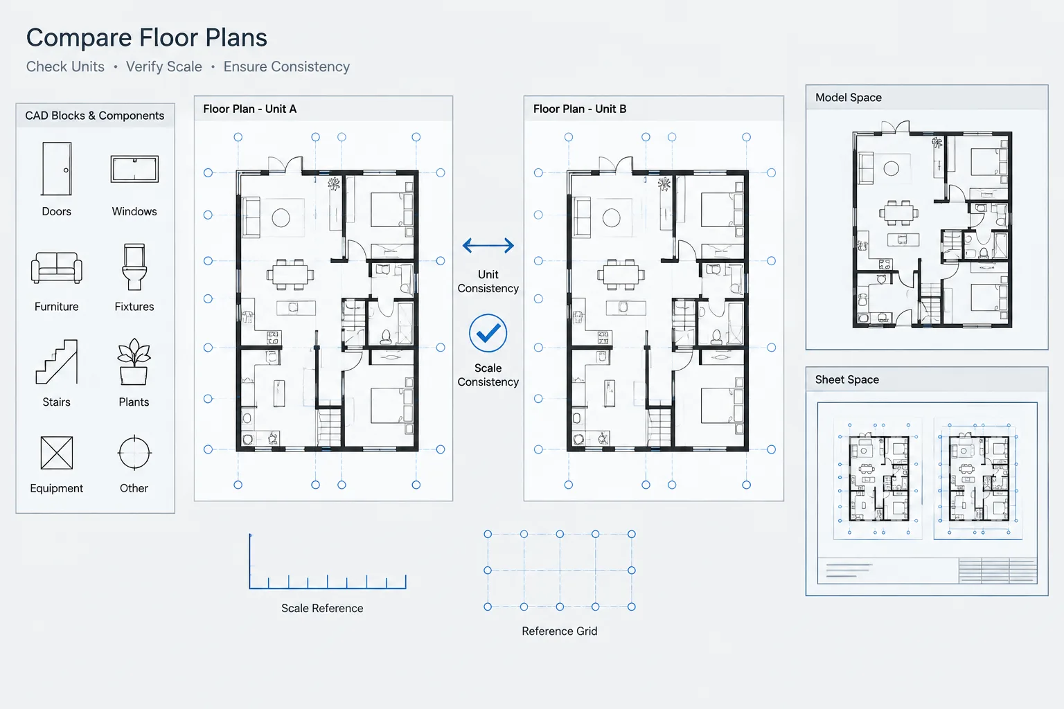
A DWG file can look correct on screen while still being drawn in the wrong units or at the wrong size. This often happens when architectural backgrounds, consultant files, survey information, manufacturer details, and downloaded CAD blocks are combined without first checking how each file was created.
A unit mismatch can make doors, furniture, walls, annotations, and entire buildings appear too large or too small after insertion. It may also create less obvious problems, such as inconsistent linetypes, hatch patterns, dimensions, viewport scales, and external-reference alignment. The safest approach is to verify geometry before editing or scaling anything.
Drawing units and plotted scale are different
Two separate ideas are commonly described as drawing scale:
- Model-space units describe what one drawing unit represents in the real world, such as an inch, foot, millimeter, or meter.
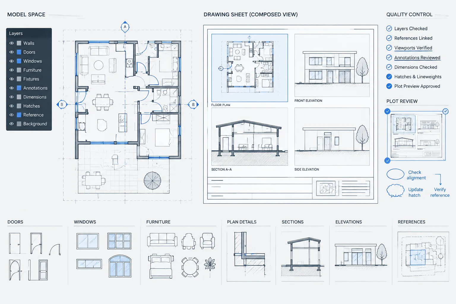
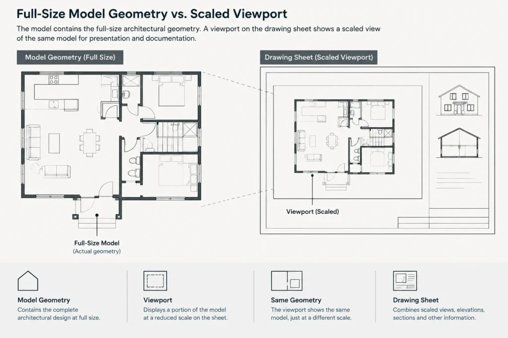
- Plot or viewport scale controls how full-size model geometry is displayed on a sheet.
Architectural geometry should generally be created at its intended real-world size in model space. A floor plan should not be reduced merely because it will be printed on a smaller sheet. The viewport or plotting setup handles that presentation scale.
A file can therefore have correctly sized model geometry but an incorrect viewport scale. It can also have a correctly labeled viewport while the underlying model is the wrong size. These conditions require different corrections.
Why unit problems occur in DWG files
Unit errors are rarely caused by geometry alone. They usually result from assumptions made during file exchange. Common causes include:
- A source file does not clearly identify its working units.
- Geometry was imported from another format with a different unit convention.
- A block was created in one unit system and inserted into a file using another.
- An insertion-scaling setting automatically resized incoming content.
- A user manually scaled a background to make it appear visually correct.
- Paper-space information was mistaken for full-size model geometry.
- A detail drawn for sheet presentation was reused as though it were a full-size building component.
- Coordinates are far from the project origin, making visual comparison or selection more difficult.
The DWG format can store unit-related settings, but those settings should not be treated as proof that the geometry is correct. A file may have been assigned a unit label after it was drawn, or its geometry may have been scaled independently of that setting.
A reliable workflow for checking units
1. Preserve the source file
Before testing or correcting an unfamiliar drawing, save a separate working copy. Do not scale a consultant background, survey, or downloaded resource in place. Keeping the original unchanged makes it possible to compare results and recover from an incorrect assumption.
2. Review the drawing context
Check the file name, title block, notes, dimension styles, layout tabs, and any accompanying transmittal information. These may indicate the intended discipline, project area, or unit system. Treat this information as supporting evidence rather than final confirmation.
A title block may identify the project units, but that does not guarantee that every object in model space follows them. Imported details and blocks can carry their own scale history.
3. Inspect the unit settings
Open the drawing-unit settings and note the current unit type and insertion-unit behavior. These settings influence display and the automatic scaling of inserted drawings or blocks. Changing the unit label alone does not necessarily resize existing geometry.
This distinction is critical: assigning a different unit setting and scaling the drawing are separate actions. Do not perform both unless the file actually requires both.
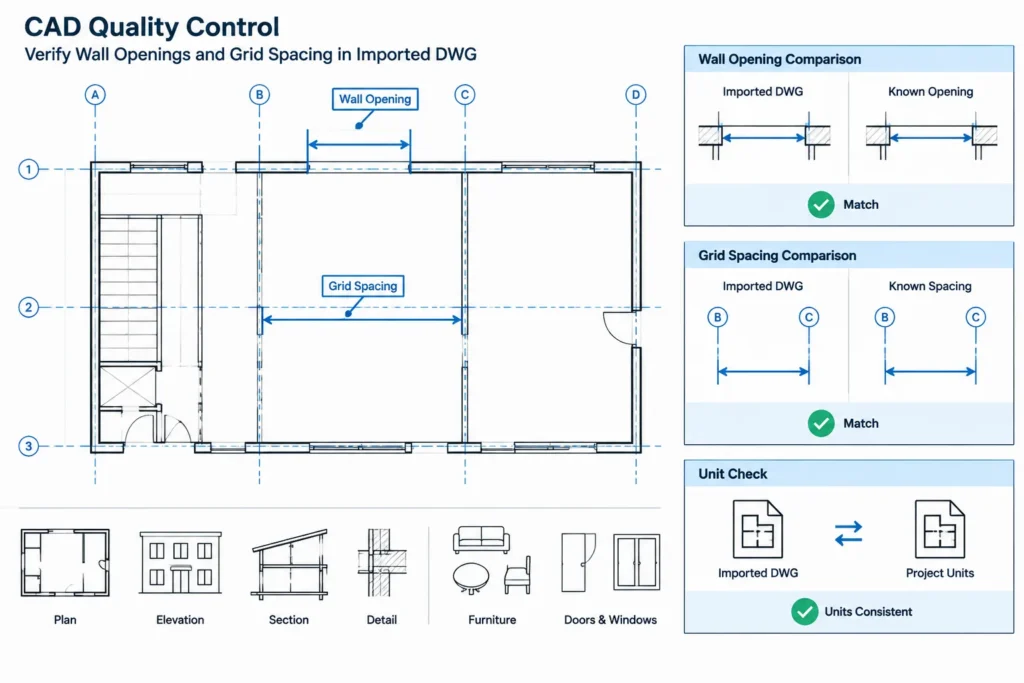
4. Measure a known object
Use a distance or object-properties tool to measure geometry with a dimension that can be independently verified. Good reference candidates include:
- A labeled structural grid spacing
- An overall building dimension
- A documented property line
- A door or window identified in a verified schedule
- A fixture tied to reliable manufacturer information
- A sheet border with a known paper size, if it is confirmed to be paper-space content
Avoid guessing from objects that merely look familiar. Furniture, vehicles, trees, generic fixtures, and downloaded symbols may be stylized or inaccurately scaled.
5. Compare more than one measurement
One matching measurement is helpful, but several matching measurements are stronger evidence. Check objects in different parts of the drawing and, where possible, in different directions. This can reveal whether the entire file has a consistent scale problem or whether only certain blocks, references, or details are incorrect.
6. Check insertion behavior in a test file
Create a controlled test drawing with verified units and insert or reference the source file. Observe whether the software applies an automatic conversion. Compare a known distance before and after insertion.
If the source is an external reference, confirm whether it arrives at the expected location, rotation, and size. A correct scale does not guarantee correct alignment, and correct alignment does not prove correct scale.
Diagnosing the type of scale error
| Observed condition | Likely issue | Recommended check |
|---|---|---|
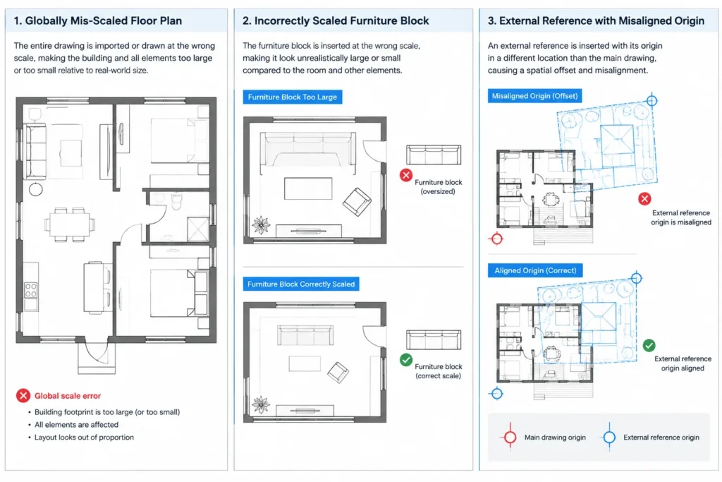
| The entire building is consistently too large or too small | Global unit mismatch or previous manual scaling | Compare several verified dimensions and review file units |
| Only one furniture or fixture block is incorrect | Block definition or insertion-scale problem | Inspect the block definition and insertion properties |
| The model is correct but sheet graphics look wrong | Viewport, annotation, or plot-scale issue | Review layout and viewport settings without scaling the model |
| Dimensions report unexpected values | Geometry may be wrong, or the dimension style may apply a conversion | Measure the geometry directly and inspect dimension settings |
| An external reference is the right size but does not align | Origin, coordinates, rotation, or insertion point issue | Compare shared control points and reference properties |
| Some details are correct while others are not | Mixed source content or sheet-based drafting | Test each detail or block independently |
How to correct a confirmed unit mismatch
Once the intended units and actual geometry size have been verified, decide whether the correction belongs in the source file, the host file, or an individual block definition.
Correcting an entire drawing
If all model geometry is uniformly incorrect, a global scale correction may be appropriate. Use a verified base point and an exact conversion factor derived from the confirmed source and target units. After scaling, update the file’s unit settings so future insertions are handled consistently.
Then recheck coordinates, dimensions, hatches, linetypes, annotation, blocks, and external references. Some objects may not behave like simple linework, especially if they depend on paper-space presentation or annotation settings.
Correcting a block
If only a block is wrong, avoid scaling the entire host drawing. Determine whether the error is in the block definition or only in a particular insertion. Editing the definition can affect every instance, while changing one insertion affects only that placed object.
Before redefining a shared block, confirm that all existing instances are intended to represent the same real-world object. A generic block name may conceal several differently scaled uses.
Correcting an external reference
For consultant or survey files, it is usually safer to preserve the received source and manage attachment settings or request a corrected file. Quietly altering a referenced background can make later updates difficult to reconcile.
Document any temporary scale, rotation, or coordinate adjustment used for coordination. When a revised file arrives, repeat the verification rather than assuming it matches the previous issue.
Objects that need special attention after scaling
A corrected outline does not mean the entire drawing is ready for use. Review the following items separately:
- Dimensions: Confirm that measured values reflect the corrected geometry and are not being altered by a style override.
- Text and tags: Check readability and intended paper-space appearance.
- Hatches: Review pattern density, origin, and boundary behavior.
- Linetypes: Confirm that dashed and centerline patterns display appropriately in model space and viewports.
- Blocks: Inspect nested blocks and attributes for unexpected scaling.
- External references: Verify attachment scale, rotation, insertion point, and coordinate alignment.
- Layouts and viewports: Make sure viewport framing and sheet annotations still correspond to the model.
Document the verified result
After resolving the issue, record the drawing’s intended units and the basis used to verify them. A short project note can identify the source file, date received, known reference measurement, and any conversion or insertion adjustment applied.
This documentation is especially useful when a project includes files from several disciplines or repeated background updates. It turns a one-time troubleshooting exercise into a repeatable quality-control process.
Final unit-check checklist
- Work from a copy of the received file.
- Separate model-space units from viewport or plot scale.
- Review unit and insertion settings without assuming they are correct.
- Measure geometry against a reliable project reference.
- Confirm the result with more than one measurement.
- Test insertion or attachment behavior in a controlled drawing.
- Correct only the affected level: drawing, reference, block, or insertion.
- Recheck annotations, hatches, linetypes, layouts, and coordinates.
- Record the verified units and any corrective action.
Unit verification should happen before a DWG becomes part of the working project set. A few deliberate checks can prevent widespread coordination errors and make architectural CAD blocks, backgrounds, and details much safer to reuse.