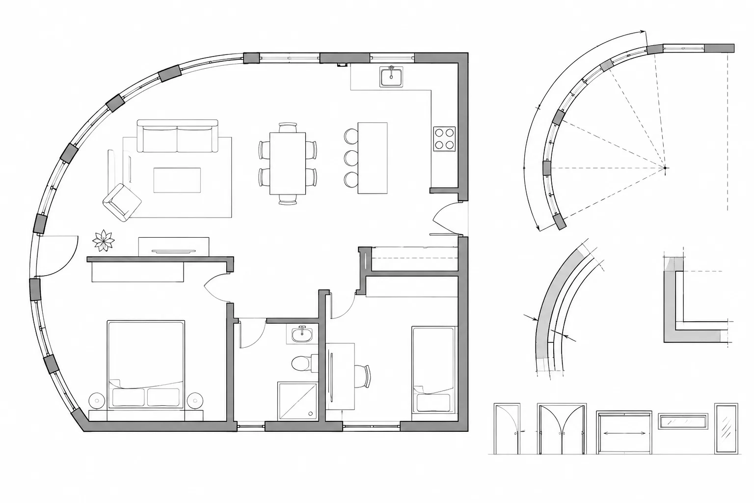
Drawing a curved wall in CAD is not simply a matter of placing parallel arcs. The wall needs a clear geometric control, coordinated faces, intentionally oriented openings, and dimensions that communicate how the curve should be located. This guide explains a practical workflow for creating curved walls that remain clean, editable, and consistent across architectural plans, elevations, sections, and details.
Curved walls can make a floor plan visually distinctive, but they also introduce drafting and coordination issues that do not occur with straight walls. The inner and outer wall faces follow different radii, openings must respond to the curve, and conventional linear dimensions may not adequately describe the geometry.
A dependable workflow begins by defining the controlling curve rather than drawing two unrelated arcs. That controlling geometry can then guide wall thickness, intersections, openings, dimensions, and related views. The goal is not simply to produce a smooth-looking plan. It is to create curved geometry that remains understandable and editable throughout the drawing set.
Choose the Geometry That Controls the Wall
Before drawing the finished wall faces, decide which curve represents the design intent. Depending on the project, the controlling line may be:
- The wall centerline
- The finished face on one side
- A structural or substrate face
- An alignment established by a grid, site feature, or adjacent room
- A series of tangent arcs defined by fixed endpoints
A centerline is often convenient when the wall thickness remains constant. A finished face may be more useful when the wall must align precisely with flooring, casework, furniture, or another visible element. Do not assume that the centerline is always the correct basis.
Place the controlling curve on a suitable construction or reference layer while developing the geometry. Keeping it separate from final wall graphics makes it easier to verify the design without confusing reference lines with plotted wall edges.
Construct a Clean Base Curve
Create the primary curve from known design information. A simple wall may be based on a center point, radius, and endpoints. Other configurations may be governed by tangent relationships, adjoining straight walls, or several connected arcs.
Avoid approximating an architectural curve with many short straight segments unless the design intentionally uses a faceted wall. Segmented geometry can create uneven offsets, difficult joins, irregular hatches, and misleading dimensions.
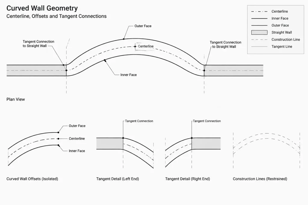
For a compound curve, inspect each transition closely. Curves that appear connected at a distant zoom level may contain small gaps, overlaps, or changes in direction. Object snaps, tangent construction, and temporary reference lines can help establish deliberate connections. Joining compatible segments into a polyline may simplify editing, but only after the individual pieces have been checked.
Verify the curve before adding detail
Confirm the following while the geometry is still simple:
- The curve begins and ends at the intended locations.
- Connections to straight walls are tangent or intentionally non-tangent.
- Adjacent curved segments meet without gaps or overlaps.
- The controlling radius or alignment agrees with the design information.
- The curve is drawn in the correct plane and at the project drawing scale.
Create the Wall Faces from the Controlling Curve
Use offset geometry to generate the required wall faces from the controlling curve. This produces a more reliable result than drawing the inner and outer arcs independently. When the wall is controlled by its centerline, offset to both sides. When one finished face controls the layout, offset from that face in the appropriate direction.
The inside and outside faces of a curved wall do not have the same radius. They should therefore not be copied or scaled as if they were identical objects. An offset maintains the intended relationship between the faces along the curve.
After offsetting, trim or extend the wall faces into adjoining construction. Examine the ends at a close zoom level. Curved-to-straight intersections often leave short remnants or gaps that may later disrupt hatches and wall cleanup.
Check tight inside curves
An offset may fail or produce self-intersecting geometry when a curve is too tight for the intended wall build-up. Treat this as a design and coordination warning rather than merely a CAD inconvenience. Review the controlling geometry, wall assembly, and adjacent conditions before manually forcing the lines to appear correct.
Resolve Curved-to-Straight Wall Connections
The junction between a curved wall and a straight wall should communicate how the construction changes direction. Common geometric conditions include a tangent transition, a radial connection, a squared termination, and an intentional corner.
Do not automatically apply a fillet simply because it creates a smooth graphic. A fillet changes the geometry and may introduce a radius that was not part of the design. Use temporary construction lines to determine whether the intended wall faces should meet by extension, trimming, tangent arcs, or a separate transition piece.
If the plan displays finish layers or multiple wall components, resolve each layer consistently. A clean outer boundary combined with crossed or disconnected internal layers can make a detail difficult to interpret.
Place Doors and Windows in a Curved Wall
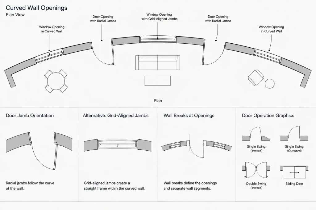
Openings in curved walls require more information than openings in straight walls. Start by identifying how the opening location is controlled. It may be centered on a radial line, located by arc length, aligned with a nearby axis, or positioned relative to a fixed endpoint.
Create the opening by breaking or trimming both wall faces with construction geometry that reflects the intended jamb orientation. Do not simply erase similar-looking portions of the two arcs. The edges of the opening should have a coordinated geometric relationship.
Decide how the jambs are oriented
Possible jamb arrangements include:
- Jambs aligned toward the center of the wall curve
- Jambs parallel to a project grid or nearby straight wall
- Jambs set by a separate design axis
- Jambs arranged to suit a framed or faceted opening assembly
The correct choice depends on the architectural design and the selected product or construction method. A generic door or window CAD block may not accurately represent a curved-wall condition. Verify frame depth, sill and head conditions, trim, and required rough opening information against the project documentation and manufacturer data.
Show door operation clearly
A conventional door swing symbol may become visually confusing against curved wall lines. Keep the leaf, hinge point, swing, and clear opening legible. If the frame or leaf is not a standard straight configuration, use project-specific geometry rather than distorting a generic block.
Dimension Curved Walls Without Ambiguity
A curved wall usually needs more than one type of dimensional control. The appropriate information depends on how the curve is intended to be laid out and constructed.
| Information | Purpose | Drafting consideration |
|---|---|---|
| Center point | Establishes the origin of a circular arc | Show it only when it provides useful layout information |
| Radius | Defines the curvature | Identify which wall face or centerline the radius controls |
| Endpoints | Locates the limits of the curved segment | Tie them to grids, walls, or other stable references |
| Tangent points | Defines transitions into adjoining geometry | Make the relationship clear rather than relying on appearance |
| Opening locations | Positions doors, windows, and recesses | State whether locations follow an axis, chord, or arc-based control |
Avoid placing a radius dimension without identifying the referenced curve when several concentric wall lines are visible. Similarly, do not combine linear, angular, and radial dimensions in a way that overconstrains the same geometry or creates conflicting instructions.
Coordinate Plans, Elevations, and Sections
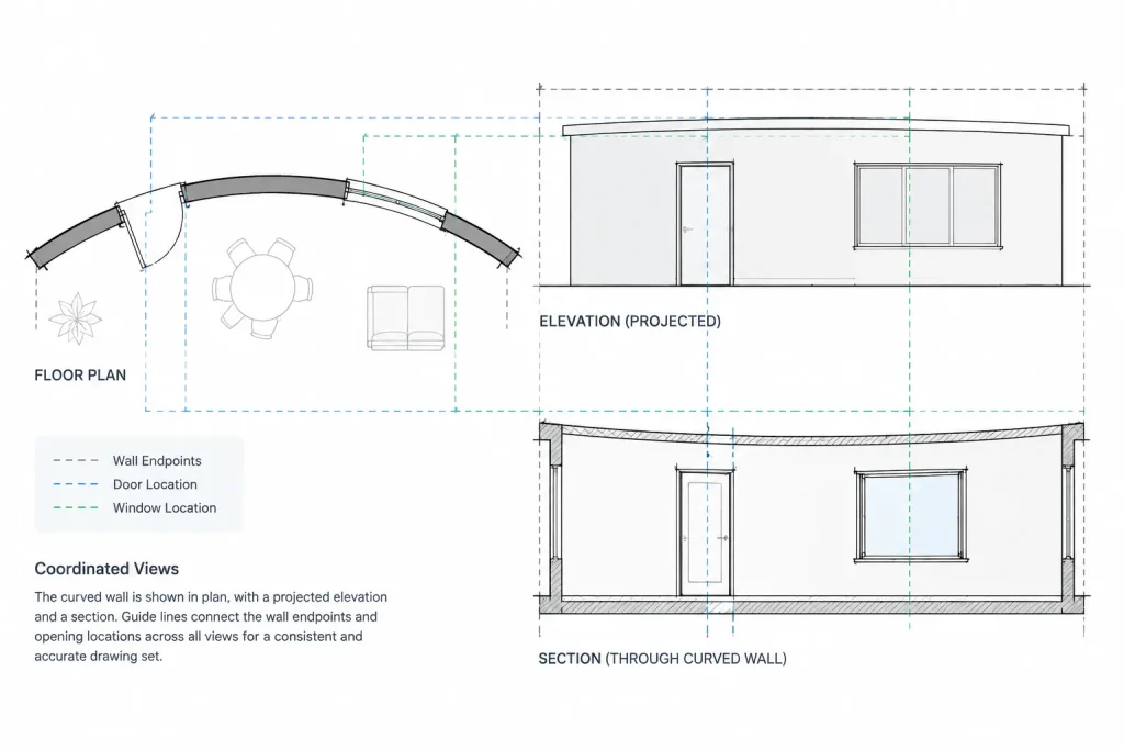
A curved wall in plan may appear flat, curved, or foreshortened in elevation depending on the viewing direction and projection method. Do not assume that copying plan geometry into an elevation will create an accurate representation.
Project key points from the plan, including wall endpoints, opening jambs, changes in height, material joints, and intersections with floors or ceilings. The elevation may need to describe how panels, cladding, trim, or joints follow the curved surface. A developed elevation can be useful for certain finish layouts, but it should be clearly distinguished from an orthographic view.
Sections should clarify the actual wall assembly, especially when the curve affects framing, finish attachment, base conditions, ceilings, or built-in elements. Use enlarged details where the general plan and section cannot communicate the transition clearly.
Hatching and Graphic Cleanup
Closed boundaries are especially important around curved walls. Small gaps at tangent points, wall ends, and openings can cause hatches to leak or fail. Before hatching, inspect the complete boundary and remove duplicated arcs or short leftover segments.
Keep wall poche, finish patterns, overhead information, centerlines, and temporary construction geometry on appropriately controlled layers. The final plotted hierarchy should make the wall outline more prominent than reference information while preserving the visibility of openings and critical joints.
Quality-Control Checklist
- Confirm which line controls the wall geometry.
- Verify radii, endpoints, and tangent relationships.
- Check that offsets created valid wall faces without self-intersections.
- Inspect curved-to-straight joins at a close zoom level.
- Confirm the orientation and width of every opening.
- Review door and window blocks instead of assuming they fit the condition.
- Identify the exact curve referenced by each radius dimension.
- Coordinate wall endpoints and openings with elevations and sections.
- Remove duplicate, overlapping, and abandoned construction geometry.
- Test the drawing at its intended plotted scale.
Build the Curve for Coordination, Not Just Appearance
The most reliable curved-wall drawings are based on a traceable geometric idea. A known centerline, finished face, radius, or tangent relationship provides a foundation for every later decision. Offsets, openings, dimensions, hatches, elevations, and details can then refer back to the same design control.
When the controlling geometry is unclear, curved walls tend to accumulate manual adjustments that look acceptable in one view but conflict elsewhere. Preserving reference geometry and checking relationships early produces a cleaner DWG file and a drawing set that is easier for other project participants to interpret.
Test the Geometry Before Issuing the Drawing
A curved wall may look correct while still being difficult to revise. Before finalizing the drawing, review a working copy and confirm that the wall can be reconstructed from its stated control. The faces should relate to the same reference curve, opening jambs should follow identifiable axes, and dimensions should describe the intended geometry rather than compensate for disconnected objects.
Diagnose common curved-wall problems
- Wall thickness appears uneven: Check whether both faces were derived from the same controlling curve. Independently drawn or scaled arcs may not maintain the intended relationship.
- An opening looks skewed: Review the jamb orientation and determine whether it should follow radial, grid-based, or project-specific control.
- Hatching fails: Inspect tangent points, opening edges, and wall terminations for gaps, overlaps, duplicate objects, or abandoned construction lines.
- The elevation conflicts with the plan: Project opening edges and other key points from the plan instead of estimating their positions visually.
- A later revision becomes difficult: Restore or recreate the controlling geometry rather than repeatedly adjusting separate wall faces by eye.
This editability test helps distinguish coordinated architectural geometry from linework that only appears correct at the current view and scale.
Frequently Asked Questions
What should control a curved wall in CAD?
The control may be a centerline, finished face, substrate face, design axis, or another established alignment. Select the reference that best represents the design intent and keep it available on a controlled construction or reference layer.
Why should the wall faces be offset instead of drawn separately?
Offsetting from a defined curve preserves the intended relationship between the wall faces. Separately drawn arcs can have mismatched centers, endpoints, or transitions even when they appear similar.
How should a door or window be placed in a curved wall?
First establish what controls the opening location and jamb orientation. Trim both wall faces using coordinated construction geometry, then verify the frame, trim, sill, head, and rough-opening requirements against the project information.
Can a standard door or window CAD block be used?
A standard block may help represent the basic component, but it should not be distorted or assumed to fit automatically. Check whether its frame geometry, insertion behavior, swing, and opening depth accurately represent the curved-wall condition.
Why can a curved-wall hatch fail?
Typical causes include small gaps, overlapping arcs, duplicate segments, and incomplete boundaries near tangent points or openings. Clean the boundary and confirm that the wall region is closed before applying the hatch.
How should a curved wall be shown in elevation?
Project relevant points from the plan and use the appropriate view type. An orthographic elevation and a developed surface view communicate different information, so the drawing should make that distinction clear.