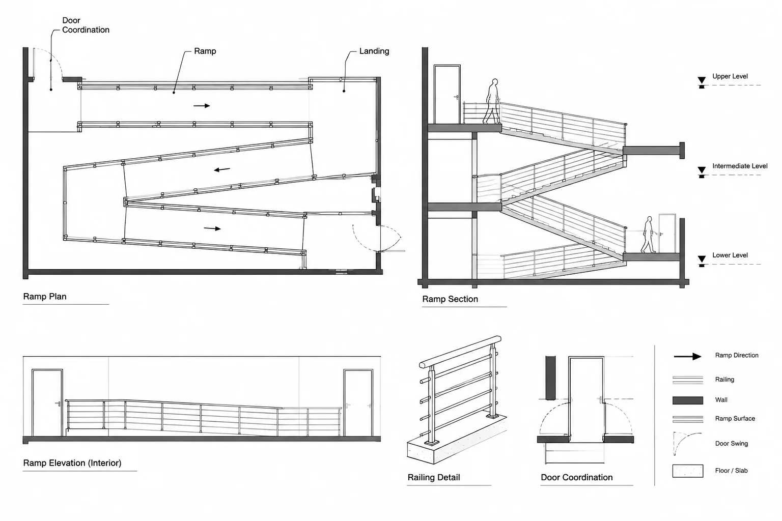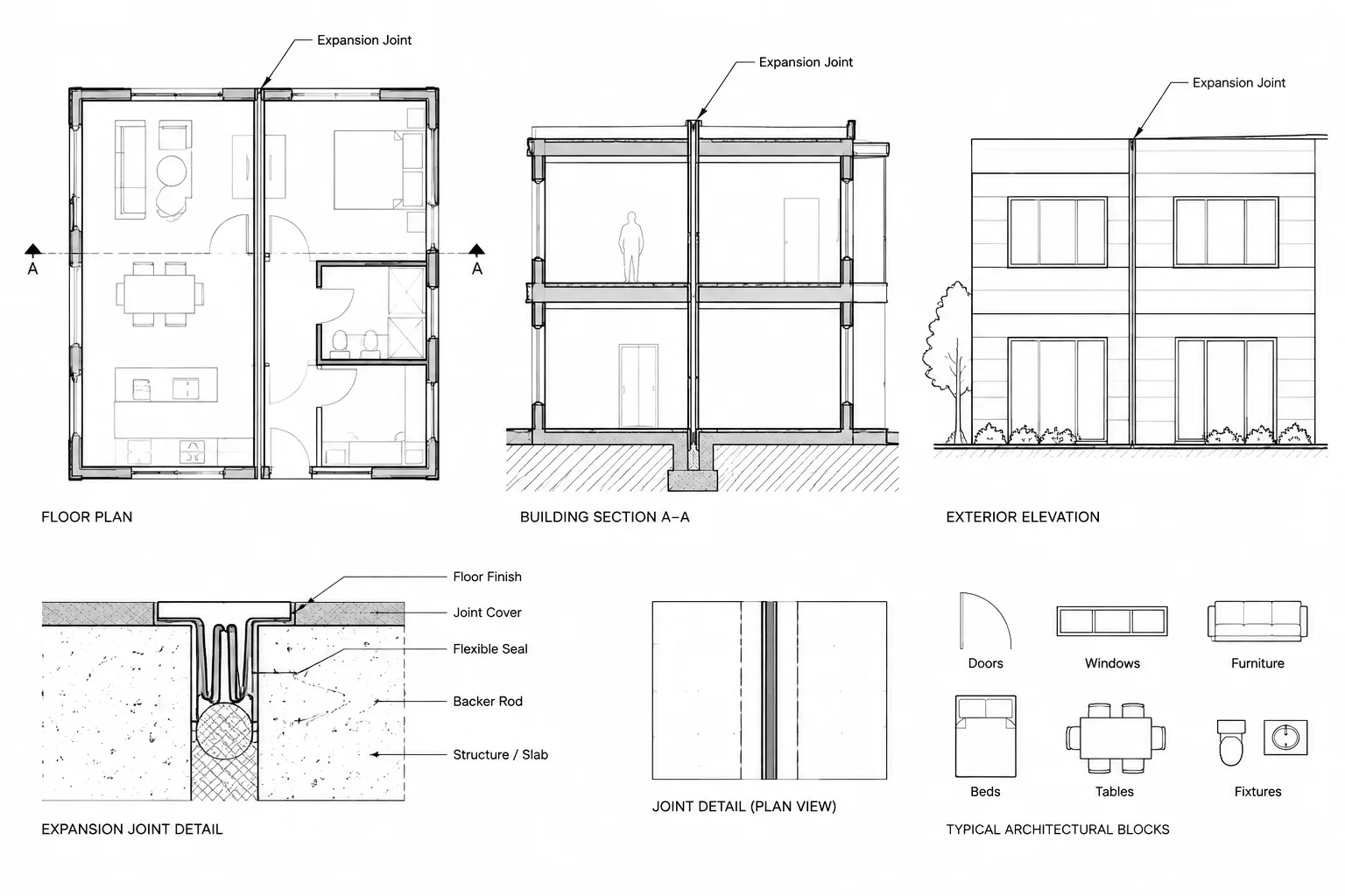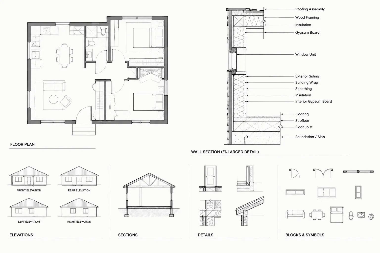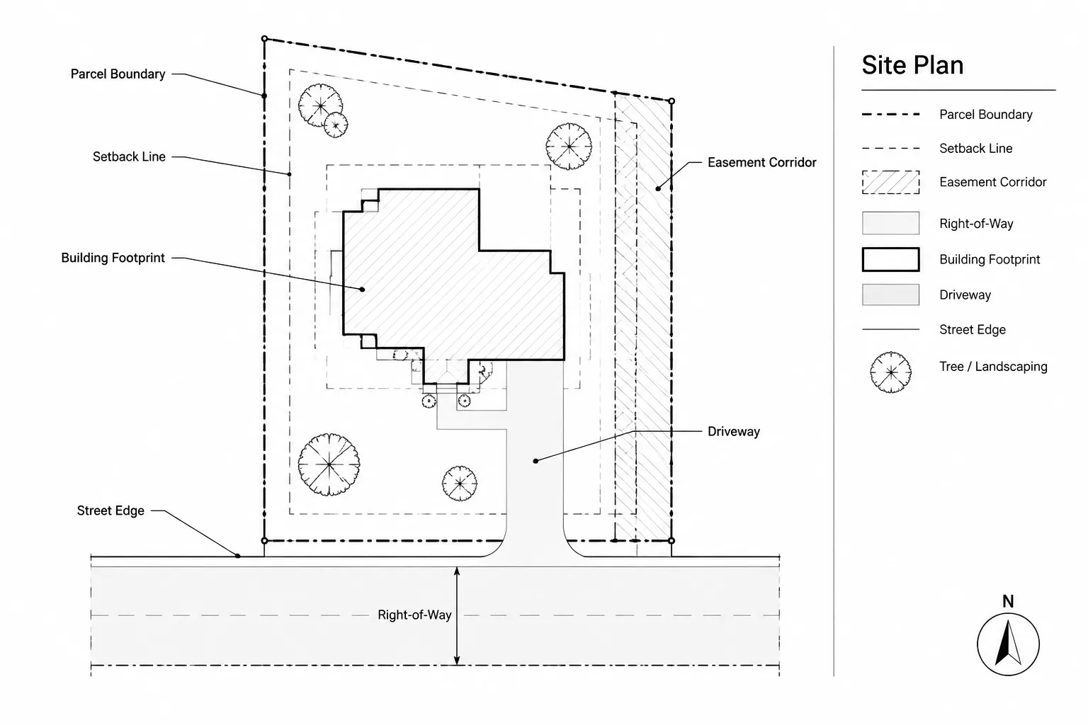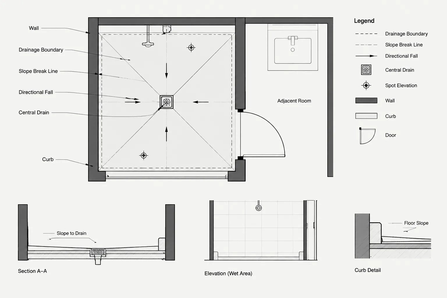
Drafting a sloped floor requires coordinated plan geometry, elevation information, drainage symbols, and detail references. The goal is not simply to show that a surface falls toward a drain, but to make the intended water path and its interfaces understandable to everyone reviewing the drawing.
This guide outlines a practical sloped floor drainage CAD workflow for organizing boundaries, break lines, arrows, spot elevations, drain locations, and related details. It also highlights the coordination checks needed before architectural drainage information is treated as resolved.
Sloped floors appear in showers, restrooms, balconies, terraces, loading areas, mechanical spaces, and other locations where water must move toward a drain or discharge point. Although the geometry may look simple, the drawing must communicate more than an arrow. It must connect the drainage intent with floor elevations, boundaries, thresholds, structure, waterproofing, and related consultant information.
A clear sloped floor drainage CAD drawing should let a reviewer answer several questions quickly: Where does the sloped area begin and end? Which direction does water travel? What controls the high and low points? Where are the drains? How does the floor meet doors, walls, curbs, and adjacent finishes? This workflow explains how to organize that information without turning the plan into a dense field of competing notes.
Start with the controlling project information
Before drawing slope arrows, collect the current architectural and consultant backgrounds. Relevant information may be distributed across the floor plan, finish plan, structural drawings, plumbing drawings, civil grading, waterproofing details, and product information.
Confirm the following items before developing the architectural graphics:
- The limits of each sloped floor area.
- The intended drain, trench drain, scupper, or discharge location.
- Established floor datums and adjacent finished floor elevations.
- Door openings, thresholds, curbs, recesses, and transitions.
- Structural slab edges, depressions, openings, and framing constraints.
- Floor finish thicknesses and substrate build-up where available.
- Drain locations and connections shown by the plumbing or civil consultant.
- Waterproofing limits and termination conditions identified by the project details.
Do not assume that a drain symbol found in a downloaded block library represents the required product or installation. Treat it as a graphic placeholder until its type, dimensions, connection, and installation conditions have been verified for the project.
Separate drainage geometry from annotation
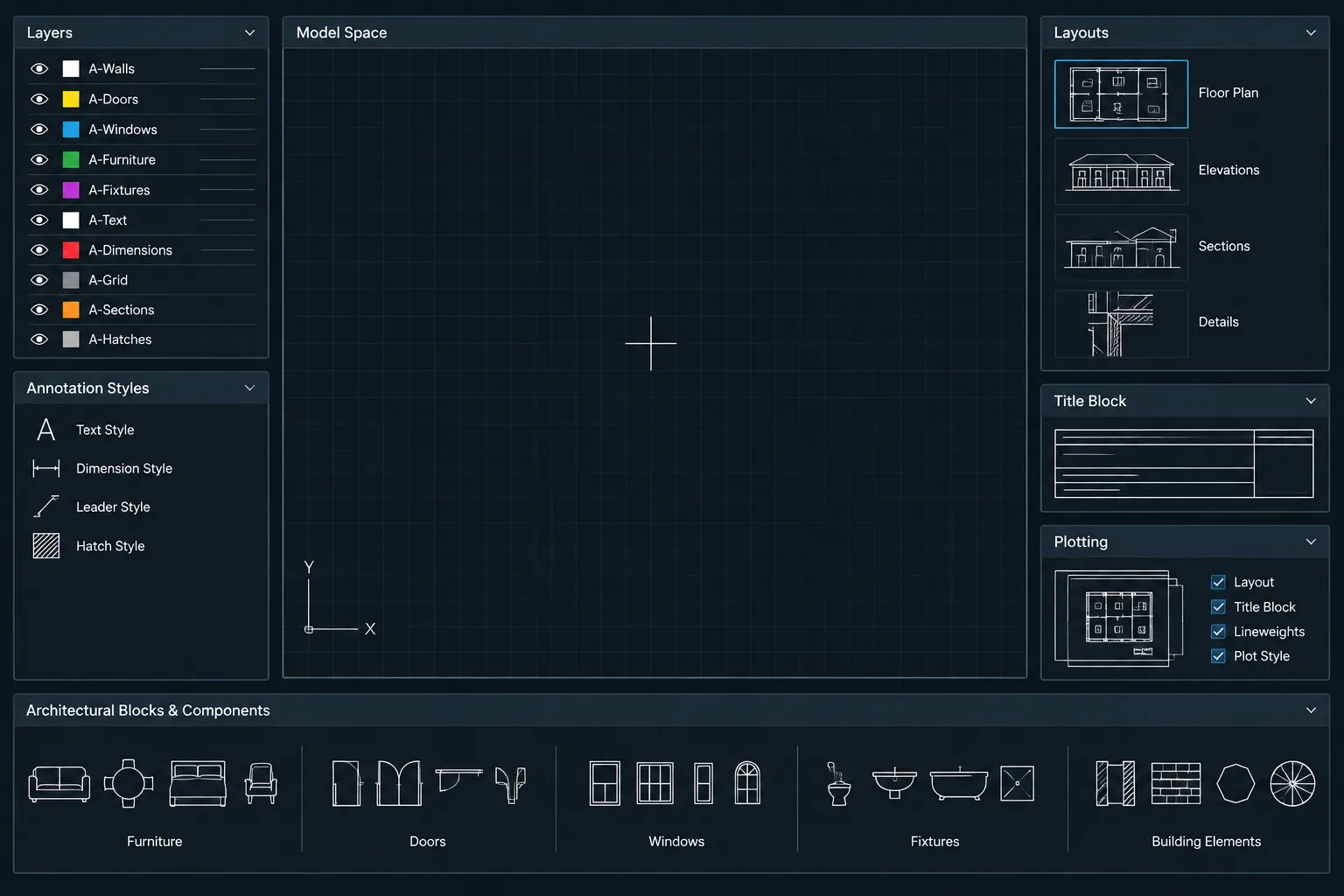
Organize sloped floor information so it can be displayed, reviewed, and revised independently. The exact layer names should follow the office standard, but separate layers are useful for drain symbols, slope arrows, spot elevations, slope break lines, floor boundaries, hatches, and notes.
This separation prevents common editing problems. For example, drain locations can be compared against a plumbing background without displaying every architectural note. Slope break lines can also be isolated when reviewing whether the modeled or drafted surface actually directs water toward the intended low point.
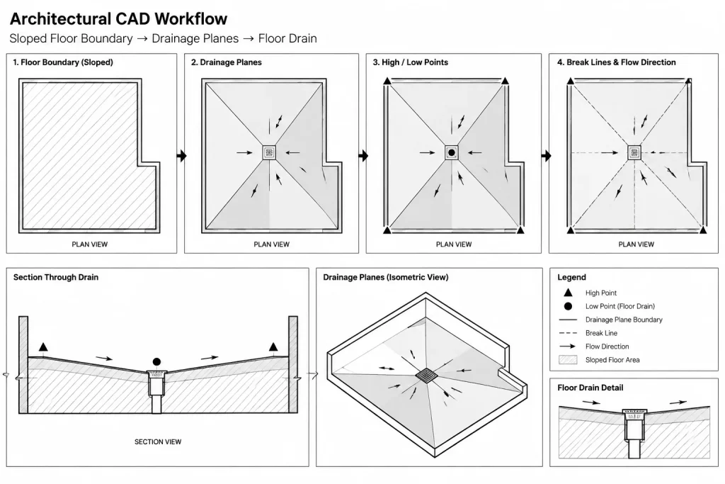
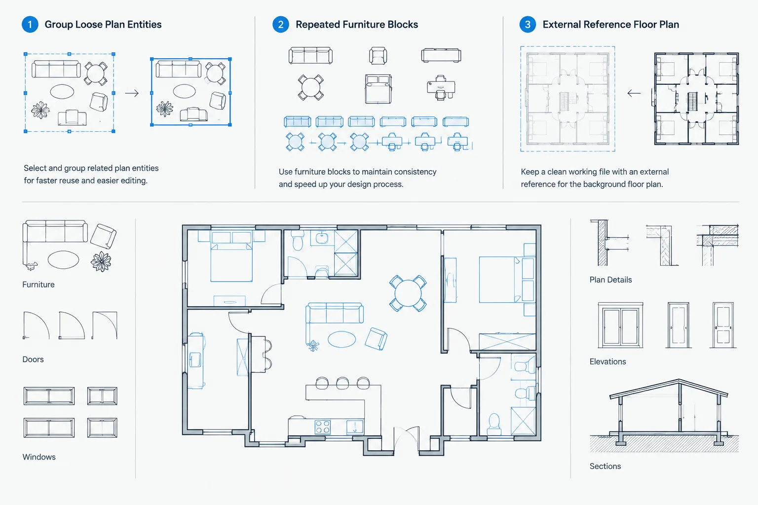
Use a consistent symbol set throughout the project. A floor drain, area drain, trench drain, and roof drain should not share an indistinguishable symbol if they serve different purposes. Each symbol should also have a predictable insertion point, preferably at the drain centerline or another clearly defined coordination point.
Define the slope boundary first
Draw the perimeter of the sloped area before adding arrows. The boundary may follow walls, curbs, door thresholds, finish transitions, slab recesses, or a designated drainage zone within a larger room.
A closed polyline can be useful for checking the extent of the area and applying a controlled hatch. However, the boundary should reflect the construction condition rather than merely outlining the room. A shower floor, for example, may have a drainage boundary that differs from the room boundary because of a curb, screen, or finish transition.
When several planes meet at a point or line, show the slope breaks that define those planes. These lines are not decorative. They indicate how the floor surface changes direction. Use a line type and weight that remain visible without being mistaken for walls, joints, or overhead objects.
Establish high points, low points, and datums
A slope arrow is meaningful only when its direction and elevation controls agree. Identify the controlling high points and low points before placing repeated arrows across the plan.
Spot elevations may be appropriate at:
- Drain rims or other designated low points.
- Door thresholds and accessible transitions.
- Corners of large sloped areas.
- Ends of trench drains.
- Changes in slope direction.
- Connections to level floors, exterior paving, or adjacent rooms.
Keep the elevation reference consistent. If one drawing uses finished floor elevation while another uses structural slab elevation, label that distinction clearly. Mixing surface elevations and structural elevations without identification can create apparent conflicts even when each value is individually correct.
Where calculations are needed, the basic relationship is slope equals vertical change divided by horizontal run. The drawing team should use project-approved elevations and requirements rather than estimating values from graphics. CAD geometry can support checking, but it does not replace confirmation by the responsible designer and consultants.
Draw slope arrows with a consistent meaning
Choose one arrow convention and use it consistently. A typical graphic includes a line and arrowhead pointing in the direction of fall, with adjacent text describing the intended slope or linking to a note. The project legend should make the meaning unambiguous.
Place arrows where they explain each drainage plane. Avoid filling a simple area with redundant arrows, but do not rely on one general arrow when the floor contains several directional planes. For radial drainage around a central drain, arrows can be distributed around the low point while slope break lines indicate how the planes meet.
Keep arrows clear of room names, dimensions, fixture outlines, and door swings. If an arrow must cross a hatch, verify that it remains legible at the plotted sheet scale. A background mask or a break in the hatch may help, but the drawing should not depend on a crowded graphic treatment to communicate basic intent.
Coordinate drains with surrounding elements
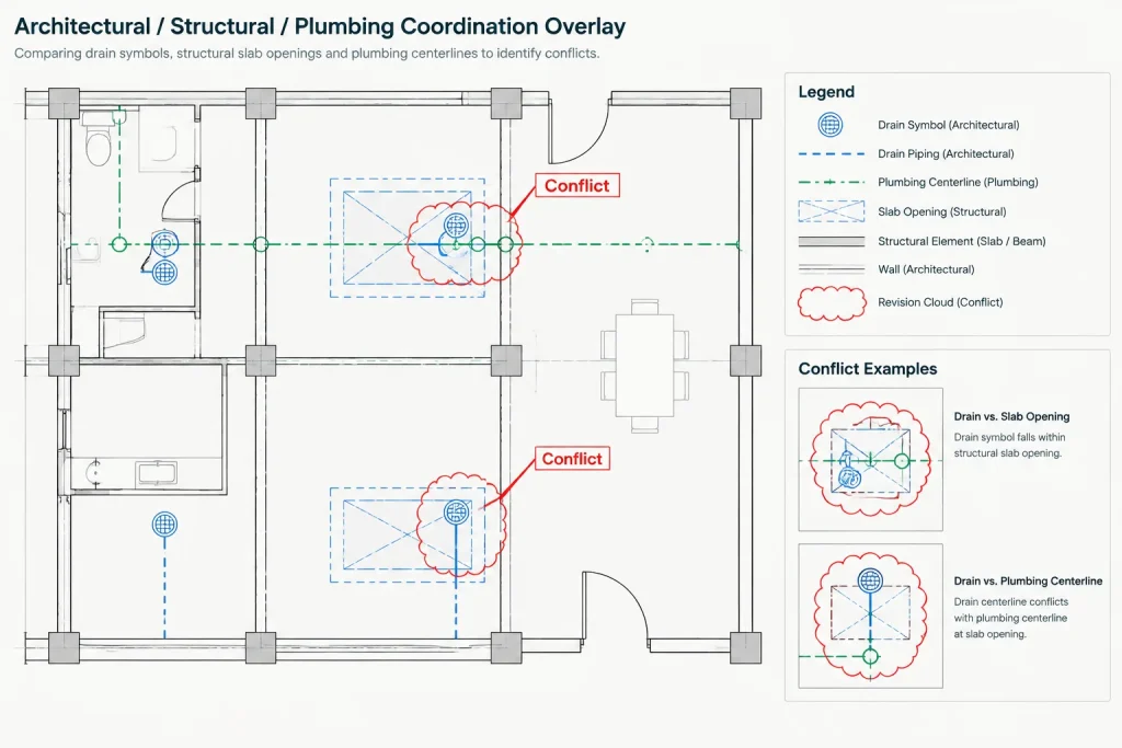
Drain placement must be checked against more than the floor finish. Compare each location with walls, partitions, equipment, casework, structural framing, plumbing routes, ceiling conditions below, and maintenance access.
| Element | CAD coordination check | Potential conflict |
|---|---|---|
| Door or threshold | Compare spot elevations and transition limits | Water directed toward an opening or an unintended level change |
| Wall or curb | Check drainage boundary and waterproofing detail references | Trapped water at an edge or unclear termination |
| Structural framing | Overlay drain centers, slab openings, and depressions | Drain body or piping conflicting with framing |
| Plumbing layout | Compare drain type, centerline, and connection intent | Architectural and plumbing plans showing different locations |
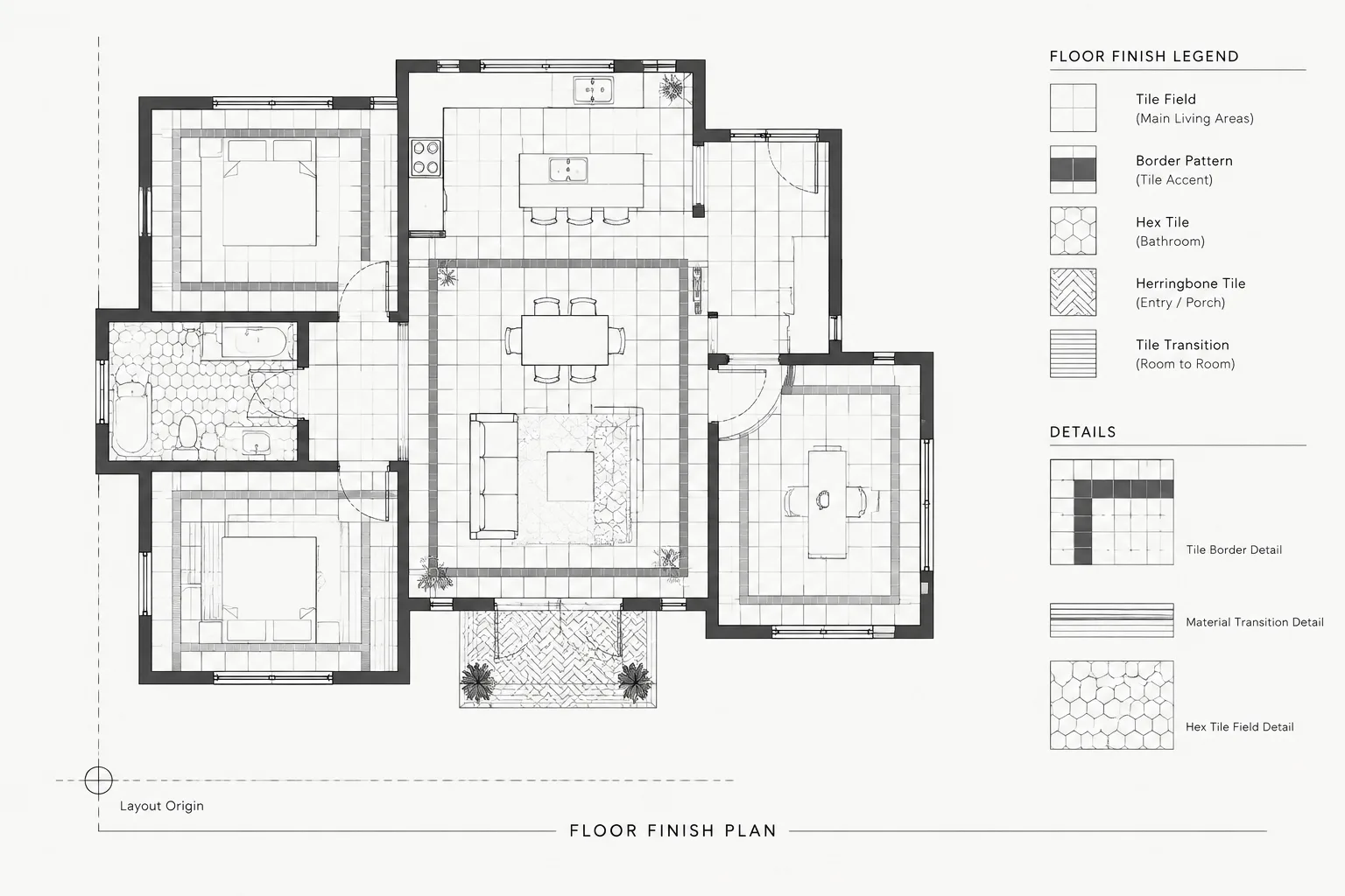
| Floor finish | Review finish direction, joints, and transitions | Small finish pieces, awkward cuts, or incompatible slope geometry |
| Ceiling below | Review reflected ceiling and equipment locations where relevant | Piping or drain components conflicting with finished spaces |
When a consultant controls the final drain position, avoid silently moving it in the architectural file. Mark the issue, communicate the requested change, and update all affected drawings after the location is resolved.
Use enlarged plans and details when the floor plan is insufficient
A general floor plan may show the existence and direction of a slope, but it is rarely the best place to describe every local condition. Enlarged plans can show drain centers, slope breaks, finish joints, thresholds, curbs, and fixture relationships more clearly.
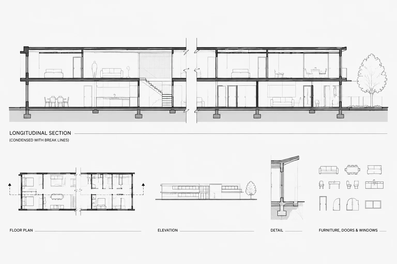
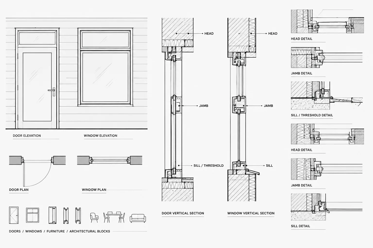
Sections and details are especially important where the vertical build-up matters. They can explain the relationship among the finished surface, setting material, sloped substrate, waterproofing, drain assembly, slab recess, curb, and adjacent floor. Include only information that has been verified for the project, and coordinate detail references with the plan callouts.
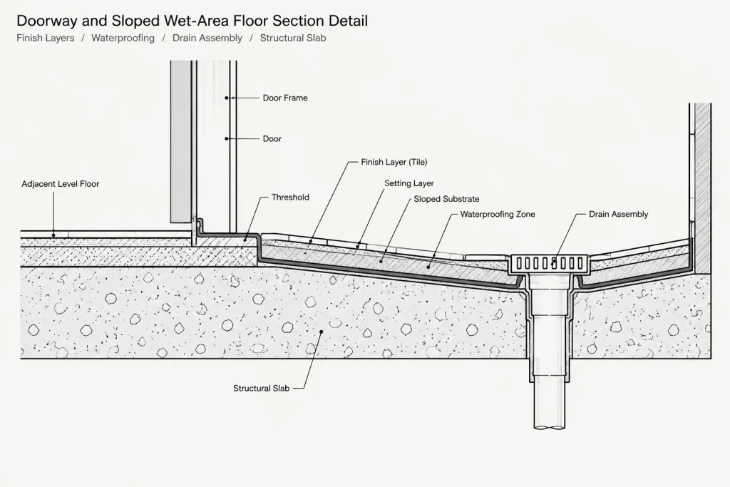
If the same typical detail applies in several locations, confirm that the surrounding conditions are genuinely equivalent. Similar-looking rooms may have different substrates, drain types, finish systems, or adjacent elevations.
Check the drawing as a connected system
Before issue, review the sloped floor plan together with the related sections, elevations, finish information, and consultant backgrounds. A strong quality-control review should include both graphic clarity and geometric logic.
- Trace the apparent water path from every high point to a drain or discharge location.
- Confirm that arrows point toward the intended low points.
- Check that spot elevations agree with the stated slope direction.
- Verify that slope boundaries and break lines form constructible drainage planes.
- Compare drain locations across architectural and consultant files.
- Review thresholds, curbs, recesses, and adjacent floor transitions.
- Confirm that plan symbols match the legend and schedule terminology.
- Plot at the intended sheet scale and check text, hatches, arrows, and lineweights.
- Remove obsolete symbols and notes left from earlier layout options.
Common drafting mistakes to avoid
One frequent mistake is drawing a slope arrow without showing the limits of the sloped area. Another is adding a drain symbol but providing no elevation or surface geometry to explain how water reaches it. Contradictory spot elevations, excessive hatching, and drain locations copied from outdated consultant files also reduce drawing reliability.
Do not use graphic precision to imply technical certainty that has not been established. A drain block can be placed accurately in CAD while still being uncoordinated with structure, plumbing, waterproofing, or finish requirements. Clearly identify unresolved items and verify applicable codes, accessibility criteria, product instructions, and consultant requirements before construction documents are issued.
A practical final drawing hierarchy
The finished drawing should present information in a deliberate order. Walls, curbs, fixtures, and floor boundaries establish context. Drain symbols and slope break lines describe the drainage geometry. Arrows and spot elevations explain direction and vertical control. Notes, tags, and detail references provide supporting information.
When these elements are coordinated rather than added independently, a sloped floor drainage CAD plan becomes more than a collection of arrows. It becomes a readable map of the intended surface, its controlling elevations, and the interfaces that the architectural and consultant teams must resolve.
Manage revisions without losing the drainage logic
Sloped floor information can become unreliable when individual annotations are revised without checking the complete drainage surface. Moving a drain may affect slope directions, break lines, spot elevations, finish joints, slab openings, detail references, and conditions in the space below. Treat these elements as a connected drawing set rather than isolated CAD objects.
When a change is received, identify its source and review every affected view. A plumbing background revision may require an architectural plan update, while a threshold or finish change may affect both the drainage plan and a section detail. If coordination is still in progress, use the project’s established issue-tracking method instead of leaving uncertain geometry to appear complete.
Prepare a focused coordination view
A dedicated review view can make conflicts easier to find. Display the drainage boundary, drain centers, relevant architectural elements, structural constraints, and the current consultant background while suppressing unrelated annotation. This view can support coordination, but the issued sheet should still contain the information necessary to communicate the final architectural intent.
Distinguish design intent from field verification
CAD linework can document the intended relationship among high points, low points, transitions, and drains, but it does not confirm existing conditions or installation tolerances. Renovation work may require field verification, and product-dependent conditions must be checked against approved project information. Notes should clearly distinguish confirmed requirements from items that remain subject to coordination.
Review the plotted result, not only the working file
A drainage plan that appears clear while zoomed in may become difficult to read on the final sheet. Review the actual plotted hierarchy to confirm that boundaries, break lines, arrows, spot elevations, drain symbols, and detail references remain distinguishable. The most important drainage information should not depend on color or extremely fine graphic differences to be understood.
Frequently asked questions
What should a sloped floor drainage CAD plan show?
It should identify the limits of the sloped area, drainage direction, high and low points, drains or discharge locations, relevant spot elevations, slope breaks, transitions, and references to supporting details where needed.
Should a slope arrow point toward the drain?
The arrow convention must be defined by the project legend and used consistently. When arrows indicate the direction of fall, they point toward the intended low point or discharge path.
When are slope break lines necessary?
Show them when the surface contains distinct drainage planes or changes direction. They help explain how adjoining planes meet and prevent the floor from being interpreted as one uniform surface.
Why are spot elevations needed if slope arrows are shown?
Arrows communicate direction, while spot elevations establish vertical control. Using both where appropriate allows reviewers to compare the graphic water path with thresholds, drains, corners, and adjacent floor conditions.
Should architectural and plumbing drain symbols be placed independently?
No. Their locations and terminology should be coordinated. If the consultant controls the drain position, proposed changes should be communicated and resolved rather than made silently in the architectural file.
Can a downloaded drain CAD block be used directly?
It may be useful as a graphic starting point, but it should not be treated as a verified product representation. Confirm the drain type, insertion point, dimensions, connection requirements, and installation conditions using approved project information.
When should an enlarged drainage plan be created?
Use an enlarged plan when the general floor plan cannot clearly show drain centers, local slope planes, thresholds, curbs, finish joints, fixtures, and detail references without excessive visual congestion.