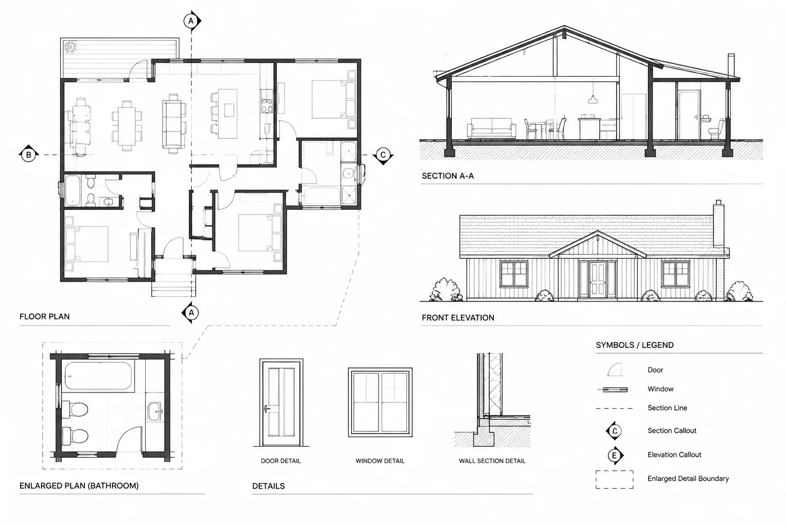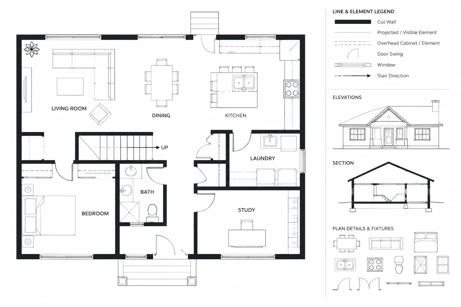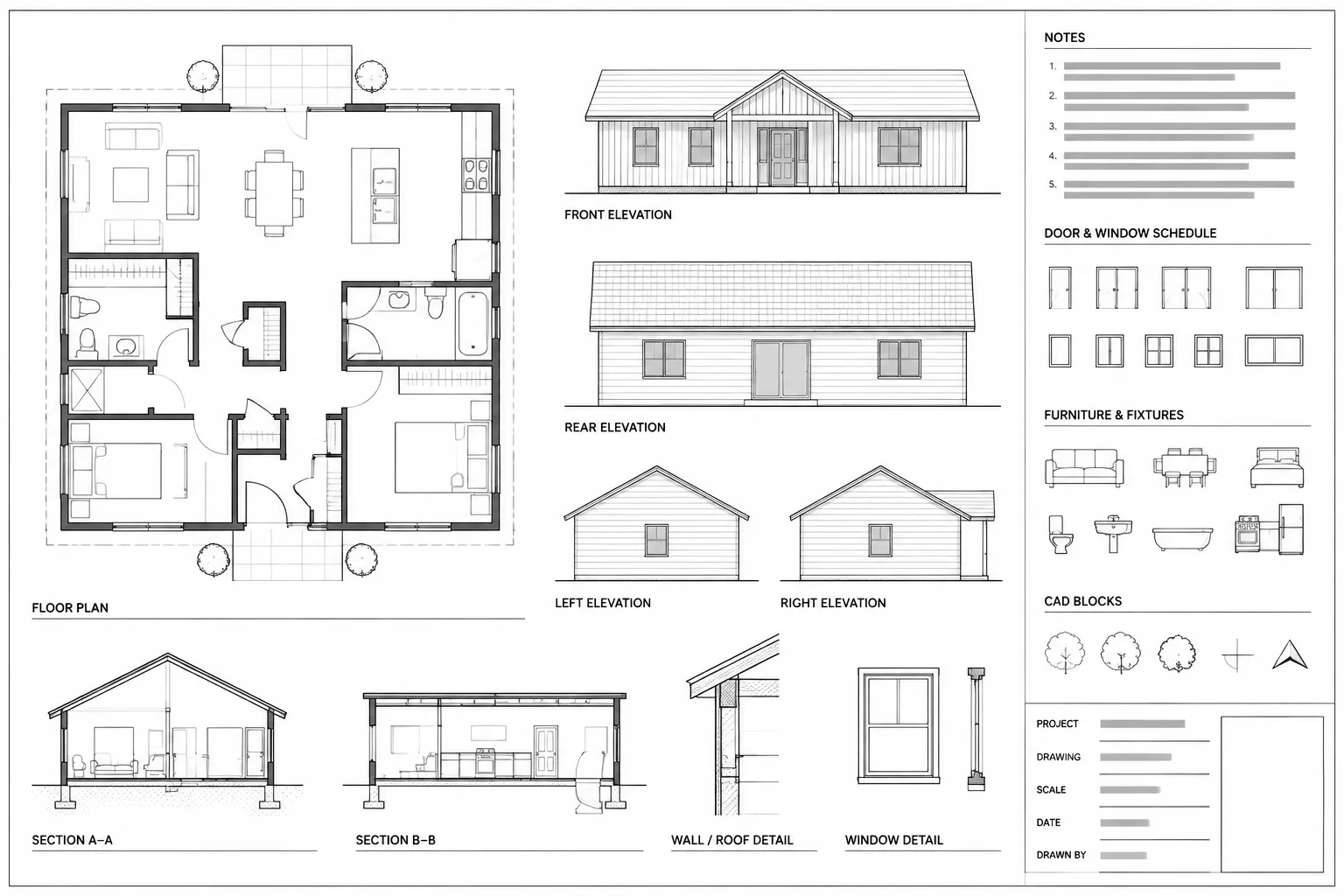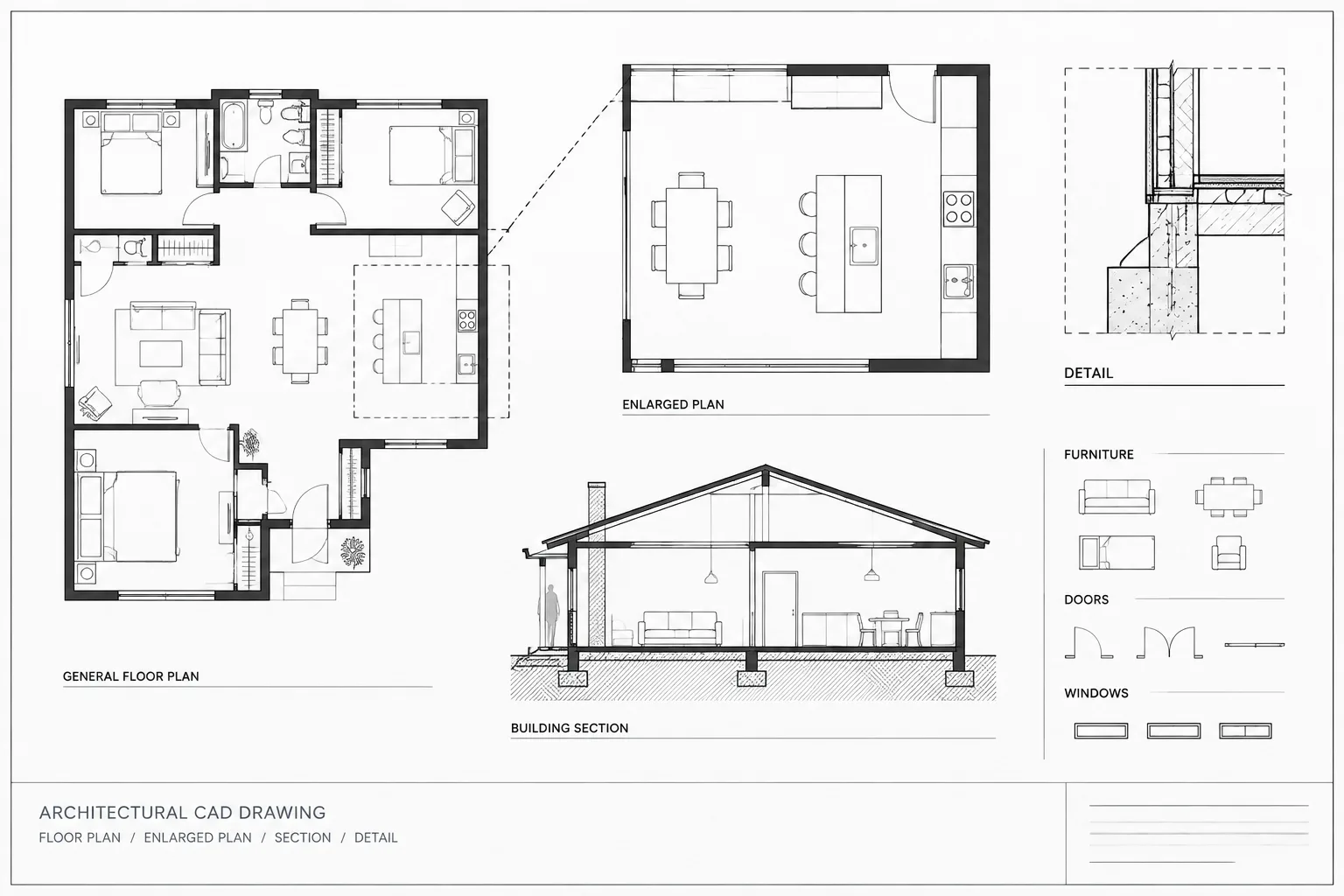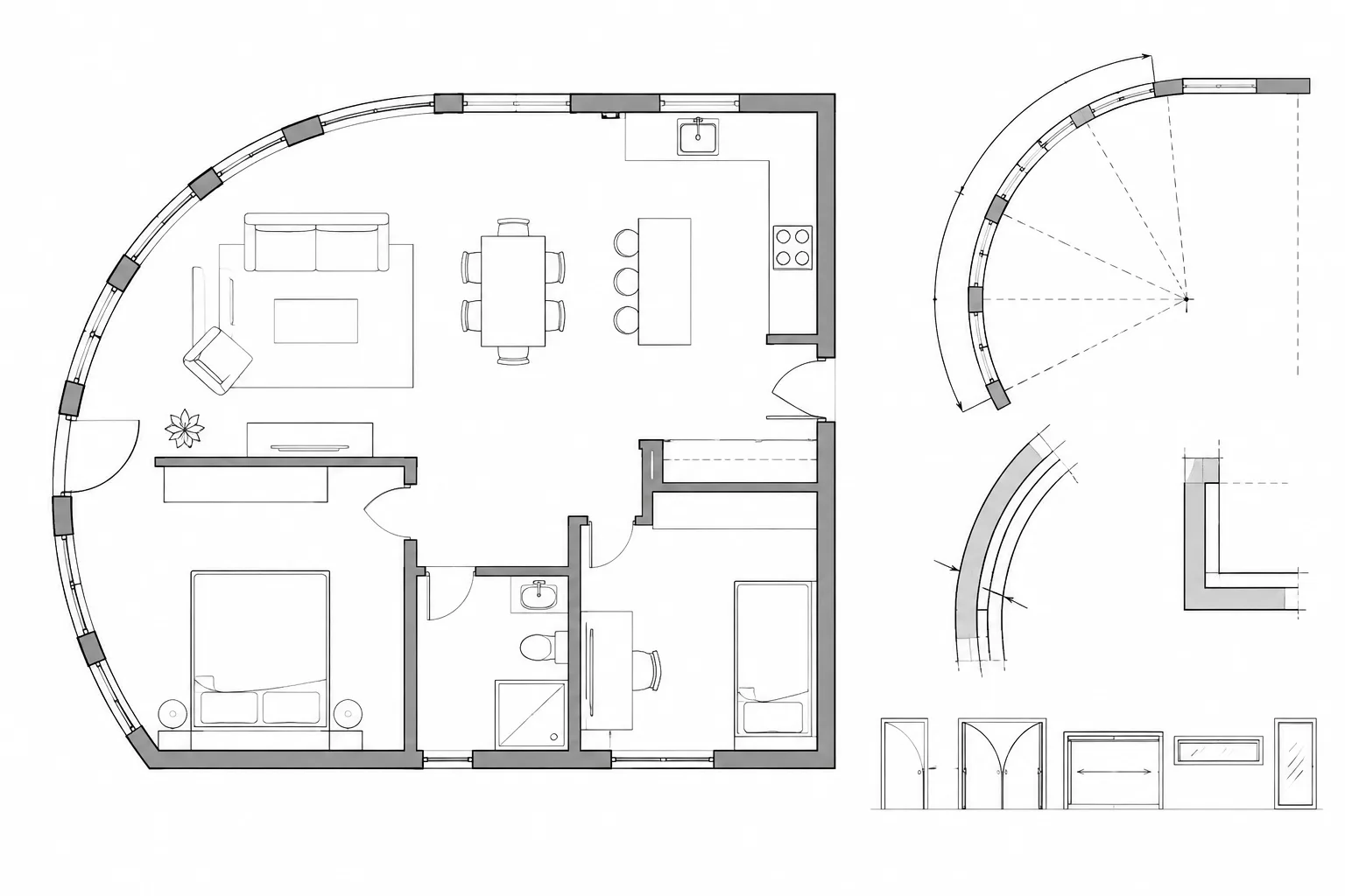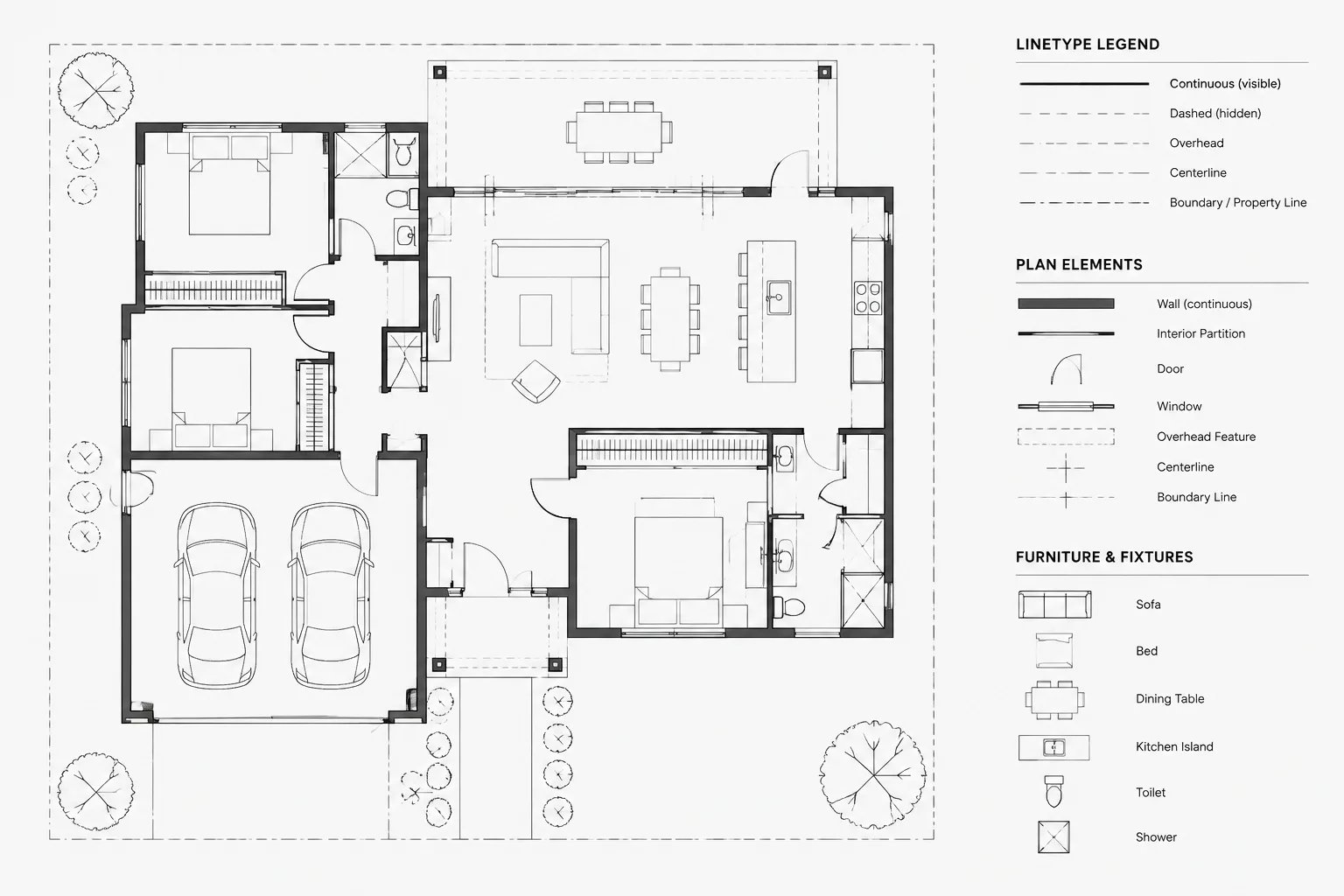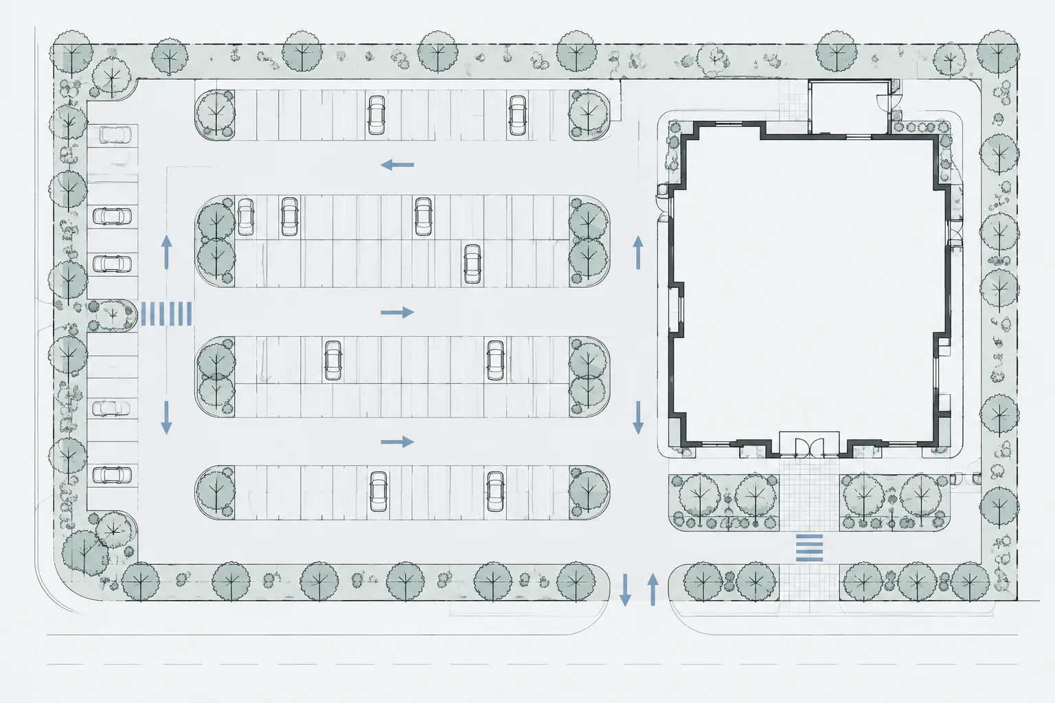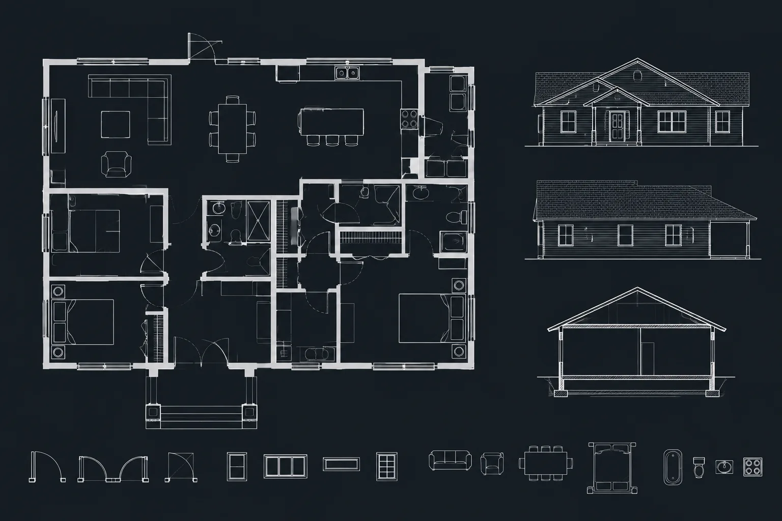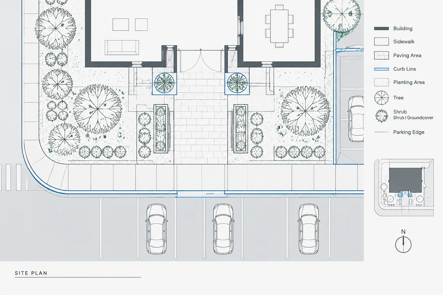
Drafting site hardscape is not simply a matter of offsetting parallel lines. Each curb, sidewalk edge, and paving boundary needs a defined meaning, a reliable source, and a clear relationship to entrances, grading, landscape work, and consultant information.
This guide presents a practical architectural CAD workflow for organizing that linework. It focuses on geometric control, layer hierarchy, reference-file coordination, transition cleanup, and drawing checks that help a site plan remain readable as the design develops.
Curbs, sidewalks, and paving limits may look like simple parallel lines, but they carry important site-planning information. Their geometry affects entrances, parking edges, landscape areas, drainage coordination, accessible routes, and the connection between a building and its surroundings. If these elements are drafted without a clear hierarchy, a site plan can quickly fill with duplicate edges, unexplained gaps, and conflicts between architectural, civil, and landscape drawings.
A reliable workflow begins by identifying what each line represents and which discipline controls it. The architectural drawing should communicate design intent without silently replacing surveyed, engineered, or jurisdiction-specific information. The following process explains how to build clean site-paving geometry in CAD and keep it coordinated as the project changes.
Identify the Controlling Background Before Drawing
Start with the current survey and the latest available consultant backgrounds. Depending on the project, curb geometry may be controlled by a civil engineer, landscape architect, architect, or a combination of disciplines. Existing public improvements may come from survey information, while proposed site paving may be developed in a separate design file.
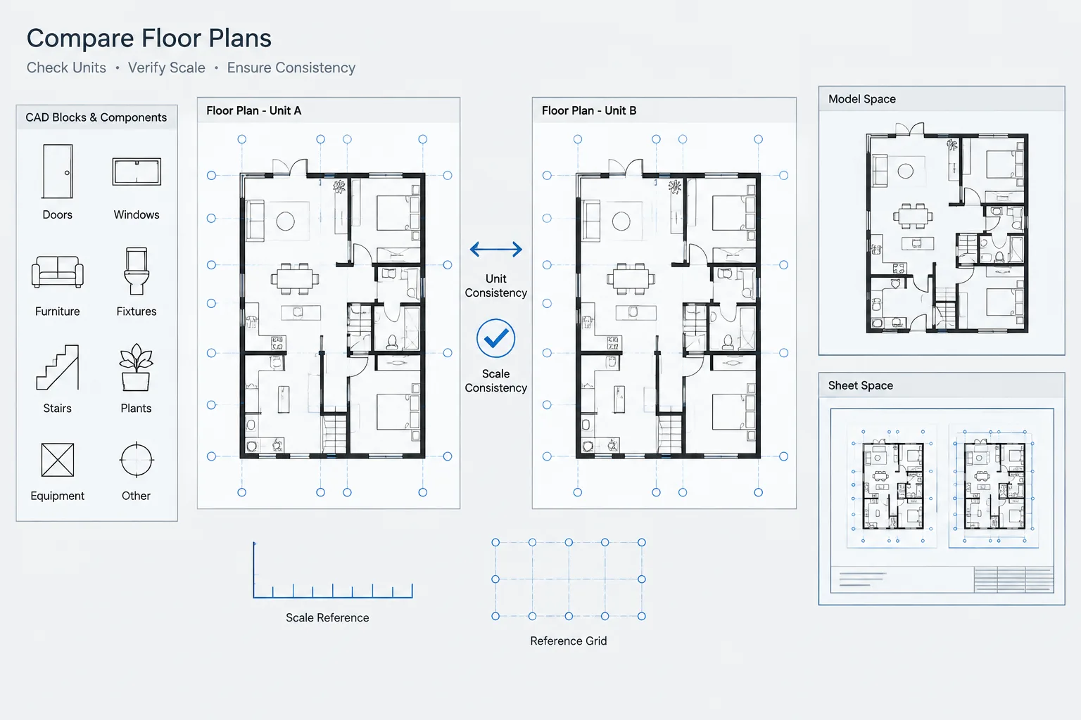
Before tracing or drawing, confirm:
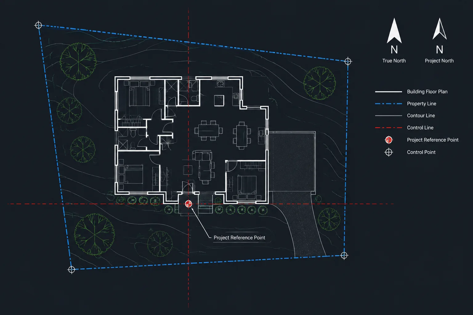
- The project coordinate system and drawing units.
- Whether the background shows existing or proposed conditions.
- Which curb line is represented: face, back, centerline, or another reference.
- Whether paving edges include gutters, planting borders, or retaining elements.
- Who is responsible for spot elevations, slopes, drainage, and accessible-route verification.
- Whether the architectural file should contain live geometry or reference consultant geometry through an xref.
Avoid redrawing consultant work merely to improve its appearance. If the source geometry is reliable, reference it and control its display with layers. Create architectural geometry only where the architect owns the layout or needs a simplified presentation for a specific sheet.
Define the Site-Line Hierarchy
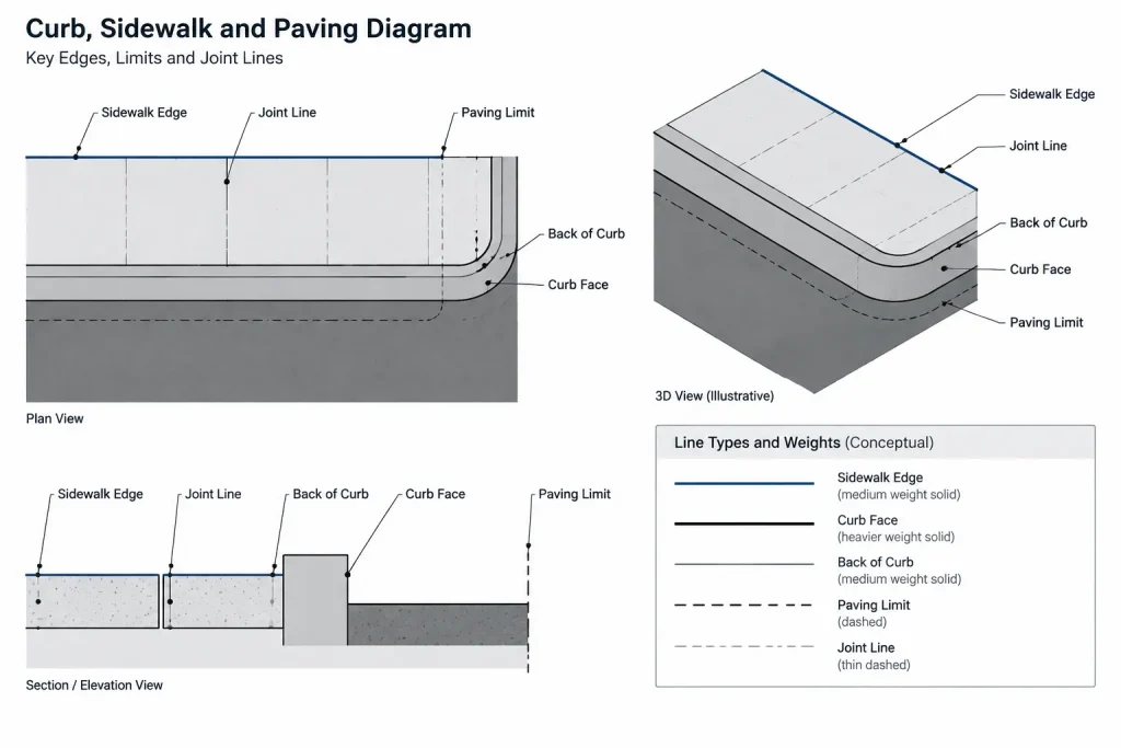
Not every hardscape line should have the same visual weight. A curb face, paving boundary, construction joint, and material hatch describe different conditions. Assigning them distinct layers makes editing and plotting more predictable.
| Drawing element | Typical purpose | Coordination question |
|---|---|---|
| Curb face or primary edge | Defines the dominant edge between pavement and an adjacent zone | Is this line controlled by architectural or civil geometry? |
| Back of curb | Communicates curb width and the boundary behind it | Does the curb type remain constant through transitions? |
| Sidewalk edge | Defines the pedestrian paving boundary | Does it align with entrances, ramps, stairs, and landscape edges? |
| Paving limit | Marks a change in surface or extent of work | Is it a material boundary, scope boundary, or both? |
| Joint line | Shows paving organization or required coordination | Is the joint layout diagrammatic or construction-specific? |
| Overhead or below-grade feature | Provides contextual coordination without reading as a surface edge | Does its linetype remain legible at the plotted scale? |
Use project layer standards rather than creating near-duplicate layers for every curb condition. Separate objects when they need different visibility, plotting, ownership, or revision control—not simply because they were drawn at different times.
Build Continuous Base Geometry
Draft the primary paving or curb edge as clean, continuous polylines where practical. Connected geometry is easier to offset, measure, hatch, revise, and check than a collection of unrelated line segments.
Establish the controlling edge
Choose one line as the geometric reference. For a curb, this might be the face or back of curb, depending on the source information and office convention. For a sidewalk, it may be the building-side edge, street-side edge, or a layout centerline. Record that decision in the drawing setup or coordination notes so another drafter does not offset from the wrong side.
Create related edges deliberately
Use an offset only when the physical element has a verified, consistent width. Do not assume that all curbs or walks remain uniform. At ramps, drive crossings, planters, steps, loading areas, and drainage structures, the parallel relationship may change. Break or reshape the derived geometry at the transition rather than forcing one continuous offset through every condition.
Clean corners and intersections
Use trim, extend, fillet, and polyline-editing tools to create intentional intersections. Zoom in far enough to find overshoots, short gaps, doubled segments, and tiny diagonal connectors. These defects may be nearly invisible on screen but can interrupt hatches, distort area calculations, and create dark spots in plotted drawings.
Draft Curb Returns and Direction Changes
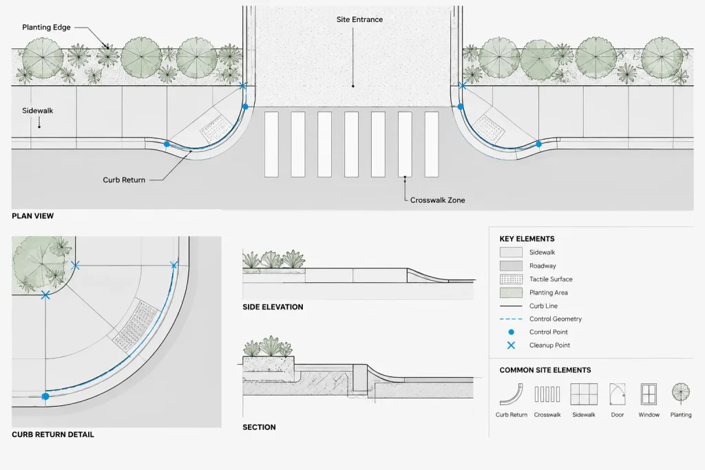
Curb returns should be treated as controlled geometric transitions, not decorative arcs added after the surrounding layout is complete. Begin with the approaching curb lines and determine which edges must connect tangentially or transition through compound geometry. Confirm the design intent with the responsible consultant when the radius, roadway alignment, drainage path, or vehicle movement affects the solution.
When editing a return:
- Keep the controlling curb edge continuous through the curve.
- Check that associated back-of-curb geometry does not overlap or collapse.
- Review the relationship to crosswalks, sidewalk approaches, planting areas, and site entrances.
- Remove abandoned arc fragments after revisions.
- Inspect the plotted result to confirm that closely spaced curves remain readable.
Vehicle templates or turning studies may inform a layout, but they do not replace civil, traffic, accessibility, or authority review. Keep analytical paths on separate layers so they can be displayed for coordination without becoming part of the finished curb linework.
Coordinate Sidewalks with Building Entrances
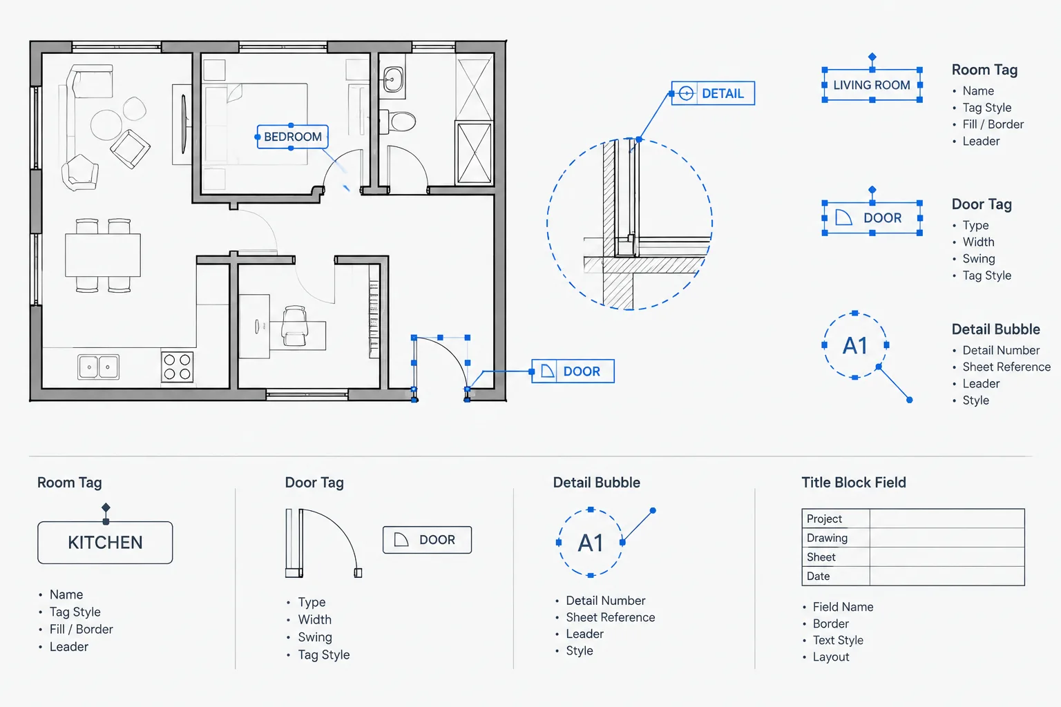
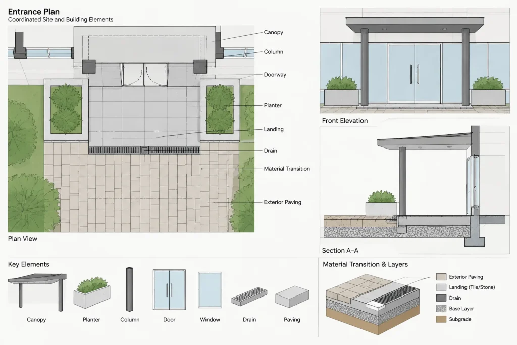
The point where a sidewalk meets a building often concentrates several drawing issues. Door landings, exterior stairs, ramps, columns, canopies, drainage elements, finish changes, and structural edges may all occupy the same area.
Reference the architectural floor plan into the site file using the established project origin. Then compare the exterior paving geometry with the actual door openings and wall faces. Avoid aligning a walk only to a schematic entrance symbol if the detailed plan has moved.
At each entrance, review:
- The clear relationship between the door, landing, and connecting path.
- Changes in paving material or pattern.
- Threshold and exterior elevation coordination.
- Canopy supports, bollards, planters, furnishings, and drainage components.
- Potential conflicts between door swings and nearby site elements.
- The need for an enlarged plan, section, or detail reference.
Do not infer compliant slopes, clearances, or landing conditions from plan graphics alone. Those requirements must be checked against the project criteria, governing regulations, and verified elevation information.
Show Paving Limits Without Creating Ambiguity
A paving limit can mean several things: the edge of a material, the boundary of new work, the extent of demolition, or the limit of a contractor’s scope. If one line is expected to communicate all of these conditions, readers may interpret it incorrectly.
Use separate layers or linetypes when material limits and work limits do not coincide. Label transitions that are not visually obvious, particularly where new paving meets existing paving of a similar appearance. In phased work, coordinate paving limits with demolition plans so the removal boundary and replacement boundary make sense together.
Hatches can clarify material regions, but the boundary line should remain understandable when the hatch is turned off or reproduced lightly. Keep hatch boundaries closed and avoid using a dense pattern to conceal unresolved geometry.
Add Joints, Patterns, and Surface Information at the Right Level
Joint layouts and unit-paving patterns should reflect the drawing’s purpose. A general site plan may show broad material zones, while an enlarged hardscape plan may communicate alignment, modules, and relationships to fixed objects.
Organize repetitive joint or pattern linework separately from primary paving edges. This allows the pattern to plot lightly, be frozen in small-scale views, or be adjusted without affecting the hardscape boundary. Where joints must align with doors, columns, drains, or site furnishings, use reference construction lines during layout and remove or isolate them before issue.
Avoid filling the model with individually drawn decorative units when a hatch or repeated block communicates the intent more efficiently. Detailed patterns should not make the DWG unnecessarily heavy or obscure critical dimensions and notes.
Coordinate Elevation-Dependent Conditions
Plan geometry alone cannot fully describe curbs and walks. Their function often depends on top and bottom elevations, slopes, drainage direction, and transitions between raised and flush conditions. Coordinate the plan with grading information and relevant sections.
Spot elevations should come from a verified source and should retain clear ownership. If elevations are referenced from a consultant file, avoid copying them into the architectural file unless the project workflow includes a method for tracking later changes. Copied values can appear authoritative even after the source has been revised.
Use sections or enlarged details where the plan cannot clearly explain a curb transition, entrance condition, planter edge, or meeting of different paving systems. A detail callout should point to an actual coordinated condition rather than a generic detail selected only because it looks similar.
Run a Focused CAD Quality Check
Before publishing or issuing the drawing, review both geometry and presentation:
- Confirm that the latest survey and consultant references are loaded.
- Check for duplicated curb and paving lines from multiple xrefs.
- Verify that polylines connect cleanly at corners and returns.
- Look for small gaps that interrupt hatches or material areas.
- Confirm that existing and proposed work are graphically distinct.
- Compare entrances against the current architectural floor plan.
- Review paving around drains, utility structures, planting areas, and columns.
- Check dimensions and notes for attachment to the intended geometry.
- Inspect lineweights, linetypes, and hatches in a plotted preview.
- Remove obsolete options, stray construction lines, and abandoned arc fragments.
Keep Design Intent and Technical Ownership Clear
The best architectural site drawings do more than show neat paving outlines. They reveal which edges control the layout, where materials change, how pedestrian routes meet the building, and where another discipline supplies technical information. Clean polylines and consistent layers help, but coordination decisions are more important than drafting speed.
Build the layout from verified backgrounds, identify the meaning of every significant line, and use enlarged views where transitions become complex. This approach produces CAD files that are easier to revise, easier to compare with consultant drawings, and less likely to hide conflicts beneath overlapping linework.
A Practical Review Strategy for Hardscape Drawings
Review curb and paving geometry in separate passes rather than trying to evaluate the entire site plan at once. Begin with ownership and source files, then inspect the primary geometry, followed by transitions, material boundaries, annotations, and plotted appearance. This sequence makes it easier to distinguish drafting defects from unresolved design or consultant-coordination questions.
Separate source accuracy from graphic clarity
A line can be graphically clean while still coming from an outdated or inappropriate background. Conversely, verified consultant geometry may need display adjustments without being redrawn. Confirm the source before correcting appearance, and use layer controls when the geometry is authoritative but visually too prominent for an architectural sheet.
Review transitions as local conditions
Drive crossings, entrance approaches, curb returns, planters, drainage structures, and changes between raised and flush edges deserve focused inspection. These locations often break the assumptions used for the surrounding parallel geometry. Treat each transition as a coordinated condition instead of forcing a typical offset through it.
Check model geometry and sheet presentation
Model-space accuracy does not guarantee a readable sheet. Inspect the work through the intended viewport and plot settings to identify merged lines, overpowering hatches, unclear limits, or consultant information that competes with architectural content. The final drawing should communicate which edges are primary, which information is contextual, and where additional details govern.
Recommended Handoff Information
When another drafter or consultant will continue the work, document the controlling background, the selected curb or paving reference edge, and the intended ownership of elevation-dependent information. Also identify temporary study geometry, copied information that requires verification, and areas awaiting coordination. Clear handoff notes reduce the risk that provisional linework will be mistaken for approved design information.
Frequently Asked Questions
Should curb and sidewalk edges be drawn as lines or polylines?
Continuous polylines are generally easier to offset, edit, hatch, measure, and check. Separate segments may still be appropriate where geometry changes ownership, condition, or display requirements. Regardless of object type, remove overlaps and close unintended gaps.
Which curb line should control the layout?
Use the edge identified by the verified source information or project convention. It may be the curb face, back of curb, or another documented reference. Record the choice so later edits are not developed from a different edge.
Should consultant curb geometry be copied into the architectural file?
Reference consultant geometry when it remains under consultant control and the project workflow supports external references. Copying creates a separate version that may become outdated. Architectural geometry is more appropriate where the architect owns the layout or needs a deliberately simplified representation.
How should a paving limit differ from a material boundary?
A paving limit may describe scope, demolition, replacement, or a surface change. If those boundaries do not coincide, show them with separate layers, linetypes, or clear notes rather than asking one line to represent several meanings.
Why do paving hatches fail or spill into adjacent areas?
Common causes include open boundaries, tiny gaps, overlapping segments, duplicate objects, or intersections that do not meet cleanly. Inspect the boundary geometry closely before changing the hatch settings.
Can the architectural site plan establish slopes and accessible conditions?
The plan can communicate design intent and coordinate routes, entrances, and transitions, but compliance cannot be inferred from linework alone. Slopes, elevations, clearances, and related criteria require verified project information and review by the responsible professionals.