A loading dock CAD plan must communicate more than the location of doors and pavement. It should explain how vehicles approach the building, how goods move through the dock, where pedestrians travel, and how architectural work interfaces with site grading, structure, utilities, and specialized equipment.
This guide presents a coordination-focused drafting workflow. It emphasizes verified project information, controlled CAD references, readable plan graphics, and the use of elevations and sections to resolve conditions that cannot be understood from plan alone.
A loading dock CAD plan must connect several systems that are often developed by different teams. The architectural drawing establishes the relationship among the building, dock doors, service yard, equipment, circulation routes, and adjacent rooms, while civil, structural, mechanical, electrical, plumbing, and specialty consultants add their own requirements.
Because these areas combine vehicles, pedestrians, level changes, weather exposure, and material handling, a dock should not be drafted as a row of overhead doors beside a paved area. A useful plan records the operational assumptions behind the layout and gives every discipline a dependable background for coordination.
Begin with the operating requirements
Before drawing detailed geometry, determine how the dock is expected to function. A warehouse receiving area, retail service dock, refuse collection point, and commercial kitchen delivery entrance may use similar graphic elements but have very different circulation and equipment needs.
Confirm available project information with the owner and relevant consultants, including:
- The types of delivery and service vehicles expected
- The number of vehicles that may arrive or queue at one time
- Whether vehicles back into bays or use another loading arrangement
- Required receiving, staging, storage, and refuse functions
- Material-handling equipment used between the vehicle and building
- Dock equipment, overhead doors, security controls, and weather protection
- Pedestrian routes for staff, drivers, and visitors
- Hours of operation and potential conflicts with public circulation
Do not select vehicle templates or dock dimensions from an unverified generic block. The design vehicle, equipment specifications, applicable regulations, and operator requirements must be confirmed for the actual project.
Organize the loading dock CAD plan in layers
A disciplined layer structure makes the plan easier to coordinate and allows information to be isolated for different sheets. Follow the project CAD standard rather than creating a separate naming system for one area.
Useful information groups typically include:
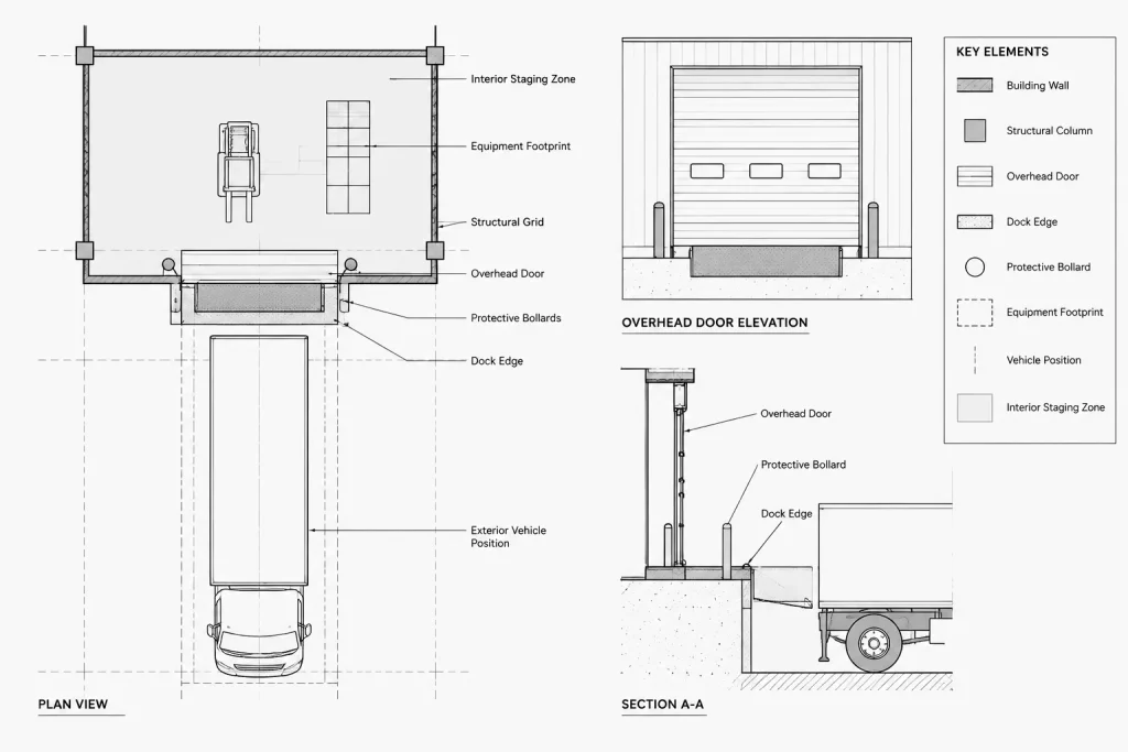
- Building walls, columns, doors, and floor edges
- Curbs, paving limits, islands, and exterior slabs
- Dock faces, pits, ramps, stairs, and changes in level
- Loading equipment and protective elements
- Vehicle outlines, swept paths, and maneuvering zones
- Pedestrian routes and crossing zones
- Drainage features and utility locations
- Canopies, lights, signs, gates, and overhead restrictions
- Dimensions, notes, room tags, and equipment references
Separate proposed construction from existing conditions and consultant reference information. Vehicle movement diagrams should also be distinguishable from permanent construction so they can be displayed for analysis without dominating the issued architectural plan.
Build the plan from stable control geometry
Start with the coordinated building grid, exterior wall, structural columns, finished floor reference, and verified site base. These elements control the dock face and should not be reconstructed from a printed sheet or a visually aligned PDF when an authoritative project file is available.
Next, establish the service-yard boundary, access route, curb lines, and interfaces with the public way or internal site circulation. Confirm that the civil and architectural backgrounds use the same origin, units, orientation, and reference geometry before developing the dock layout.
Place dock doors as coordinated openings
Each dock door should be treated as a building opening connected to several other elements. Coordinate its identifier, width and height information, wall construction, structural framing, interior clear area, exterior equipment, and schedule entry. The plan should also indicate whether a door is at a raised dock, at grade, or associated with another loading condition.
Show door leaves or overhead-door indicators according to the office drafting convention. Avoid using a generic swing graphic that misrepresents how the specified assembly operates. Headroom, tracks, operators, controls, and protective guards may require additional elevation or section coordination even when they are not visible in plan.
Show the dock edge and equipment footprint
Draw the actual limits of dock-related construction rather than representing the dock face with a single unexplained line. Depending on the project, the plan may need to identify dock leveler pits, edge equipment, vehicle restraints, bumpers, seals or shelters, control stations, wheel guides, bollards, and maintenance access.
Use simplified plan symbols where full equipment geometry would make the drawing unreadable. Reference enlarged plans, elevations, sections, or equipment details for information that cannot be communicated clearly at the overall plan scale.
Test vehicle access and maneuvering
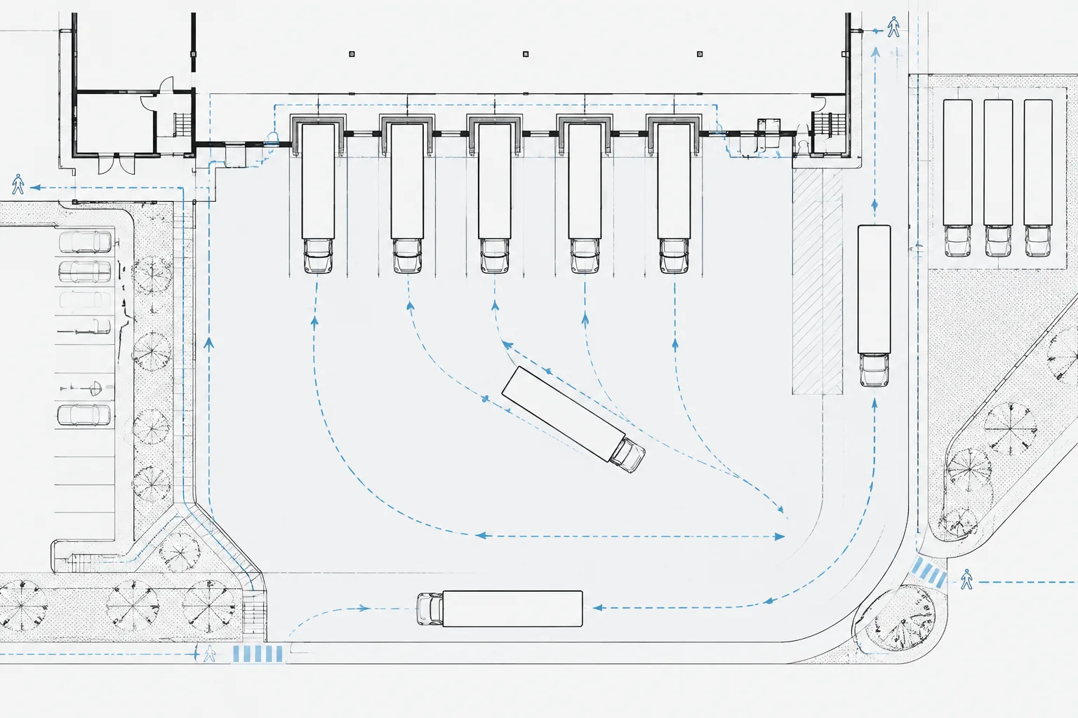
A loading bay may fit against the building while remaining unusable from the site approach. Evaluate the entire vehicle movement sequence: entry, internal travel, turning, alignment, reversing, loading position, departure, and any required queuing.
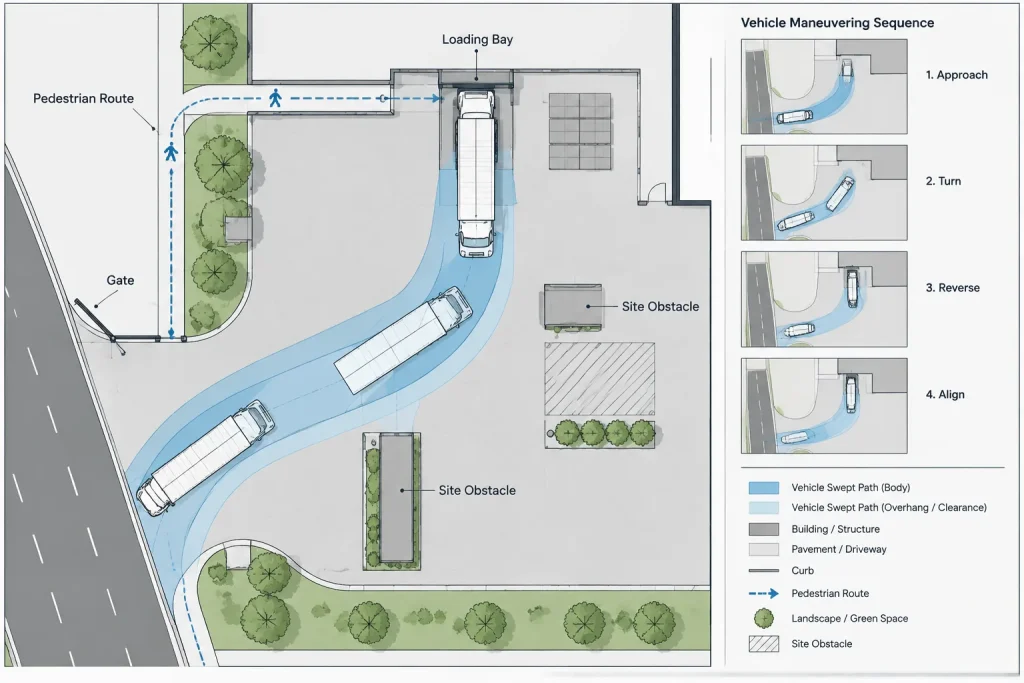
Use a verified vehicle definition appropriate to the project. A vehicle block is useful for showing a parked condition, but a swept path is more informative because it reveals the space occupied during movement. Keep these analysis graphics on dedicated layers and label the vehicle assumption so reviewers understand what was tested.
Check for conflicts with:
- Building corners and projecting canopies
- Curbs, islands, fences, gates, and guard elements
- Parked vehicles and designated parking aisles
- Fire department access or other protected site routes
- Pedestrian paths and staff entrances
- Refuse containers and collection movements
- Utility equipment, poles, hydrants, and landscape features
- Slopes, retaining conditions, and abrupt grade changes
Vehicle-path graphics are design aids, not proof that the layout satisfies every operational or regulatory requirement. Obtain appropriate specialist review where turning analysis, transportation operations, or site access is outside the architectural team’s scope.
Coordinate levels, drainage, and sections
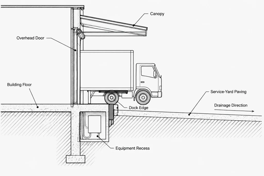
Loading docks depend on vertical relationships that can be difficult to understand in plan alone. Coordinate the building floor, dock surface, service-yard paving, door threshold, drainage points, equipment pits, ramps, and nearby site grades.
Add spot elevations or level references according to the project documentation system, but do not duplicate civil information without a clear source and responsibility. Conflicting elevation labels are more dangerous than a deliberate reference to the controlling civil drawing.
Develop sections early through representative bays and transition areas. A dock section can reveal conditions that the plan obscures, including:
- The relationship between vehicle bed, dock edge, and building floor
- Slab edges, recesses, and equipment pits
- Wall base construction and weather protection
- Door head clearance and overhead operating equipment
- Canopy projection and vertical clearance
- Paving slopes, drainage direction, and trench locations
- Guarding, stairs, ramps, or level transitions
Section callouts should point to the actual coordinated section rather than a generic detail that does not match the plan condition.
Separate vehicle and pedestrian circulation
Identify how drivers and employees travel between the yard, dock office, receiving area, and building interior. A clear plan distinguishes pedestrian movement from vehicle maneuvering and material-handling routes.
Show relevant walkways, doors, stairs, ramps, gates, protective barriers, crossing points, and changes in level. Where a route passes near moving vehicles or dock edges, coordinate the protective strategy with the owner, safety consultant, and applicable authorities. Do not assume that a painted line alone resolves a physical circulation conflict.
Coordinate the dock across disciplines
| Discipline | Key information to coordinate |
|---|---|
| Architectural | Openings, rooms, circulation, weather protection, equipment layout, finishes, and drawing references |
| Civil | Access routes, paving, grading, drainage, curbs, utilities, and site limits |
| Structural | Dock walls, slabs, pits, edge reinforcement, columns, framing, canopies, and equipment support |
| Mechanical | Heating or ventilation equipment, air intakes, exhaust locations, and overhead coordination |
| Electrical | Equipment power, controls, lighting, communications, security devices, and service clearances |
| Plumbing | Drains, piping, washdown provisions, and freeze-sensitive conditions where applicable |
| Equipment supplier | Verified footprints, recesses, operating zones, mounting conditions, and service access |
Use consultant drawings as references rather than copying their objects into the architectural model without ownership or update control. If critical information must appear on multiple sheets, establish which discipline controls it and include a coordination note where appropriate.
Annotate without overcrowding the plan
An overall dock plan should explain the arrangement, not carry every installation instruction. Use consistent door tags, equipment identifiers, level references, section markers, and keyed notes. Move dense conditions to enlarged plans and details.
Dimensions should communicate design intent from stable references such as grids, wall faces, dock edges, and opening centers or jambs, depending on the project convention. Avoid long chains based on temporary equipment outlines. If equipment controls a recess or opening, reference the verified supplier information and coordinate the dimension with structural and architectural drawings.
Loading dock CAD quality-control checklist
- Confirm that architectural and civil backgrounds share the correct coordinates and units.
- Verify dock-door locations against plans, elevations, schedules, and structural openings.
- Check the design vehicle and turning analysis source.
- Review maneuvering paths with gates, curbs, parking, refuse areas, and site equipment visible.
- Confirm floor levels, paving grades, pits, ramps, and drainage references.
- Check equipment footprints against current supplier information.
- Review overhead doors, canopies, lights, utilities, and vertical clearances in elevation or section.
- Trace pedestrian routes between the yard, receiving spaces, and building interior.
- Verify that columns, bollards, guards, and controls do not obstruct equipment operation.
- Remove obsolete vehicle paths, duplicated linework, and superseded equipment blocks before issue.
A successful loading dock drawing makes operations understandable across multiple views. By starting with verified operational assumptions, testing complete vehicle movements, coordinating levels in section, and controlling consultant references, the architectural CAD plan becomes a useful coordination document rather than a collection of disconnected symbols.
Use the dock plan as a coordination record
The most useful loading dock drawing distinguishes confirmed design information from items that remain under review. Door openings, dock edges, equipment footprints, vehicle assumptions, and site levels should be traceable to their controlling source. When information changes, the team can then identify which plans, schedules, elevations, sections, and consultant files require revision.
Review the drawing by operational sequence
Instead of checking isolated objects, follow the expected movement through the site. Trace the vehicle from the access point to the loading position and back out of the service area. Then trace the movement of materials from the vehicle through the dock opening to receiving, staging, storage, or another interior destination. Review pedestrian travel separately so conflicts are visible rather than concealed beneath equipment or vehicle graphics.
Distinguish physical construction from analysis graphics
Permanent work, movable equipment, vehicle paths, clearance studies, and consultant references should remain graphically distinct. This helps reviewers understand which lines represent construction and which lines document a design test. It also allows analysis overlays to be turned off when preparing a cleaner issued plan.
Maintain revision control
Loading dock layouts can be affected by changes to equipment, vehicles, structural framing, grading, drainage, or building operations. Record the source of critical background information and avoid keeping detached copies that will not update with the controlling file. Before issue, compare related views and schedules so a revised plan condition is not contradicted elsewhere in the drawing set.
Loading Dock CAD Questions
What should be shown on a loading dock CAD plan?
The plan should show the building interface, dock openings, dock edge, relevant equipment, service-yard geometry, vehicle movement assumptions, pedestrian routes, level references, drainage coordination, protective elements, and links to supporting elevations, sections, schedules, or details.
Is a parked vehicle block enough to test a loading bay?
No. A parked outline shows the final position but does not explain how the vehicle enters, turns, aligns, reverses, or departs. A verified swept-path study provides a more useful movement check, although specialist review may still be required.
Why are sections important for loading dock coordination?
Sections reveal vertical relationships among the building floor, dock edge, equipment recesses, paving, drainage, overhead doors, canopies, and operating clearances. These relationships are often ambiguous or invisible in plan.
How should consultant information be handled in the architectural CAD file?
Use controlled consultant references whenever possible and identify which discipline owns critical information. Avoid copying objects into the architectural file without a process for tracking updates, responsibility, and superseded data.
How can a loading dock plan remain readable?
Separate information by layer and graphic purpose, use consistent tags and callouts, and move dense equipment or construction conditions to enlarged plans and details. Analysis graphics should remain distinguishable from permanent work.
Can generic loading dock CAD blocks be used for final coordination?
Generic blocks may help with early studies, but they should not replace verified vehicle definitions, supplier information, project requirements, or consultant input. Final geometry must be checked against the actual design basis.