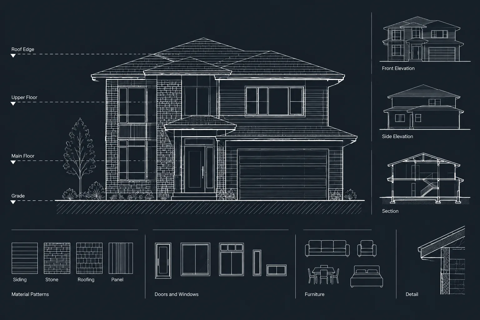
To draft and coordinate exterior elevations effectively, CAD users must treat each view as part of a connected drawing set rather than an isolated façade study. Plans establish horizontal locations, sections establish vertical relationships, and roof, site, opening, and material information complete the visible building envelope.
This guide explains a practical workflow for projecting geometry, organizing linework, checking adjacent views, controlling graphic hierarchy, and managing revisions. It is useful when creating elevations from current project backgrounds or reviewing elevation drawings received from another CAD source.
Exterior elevations communicate the vertical organization and outward appearance of a building. They show the relationship among grade, floor levels, roofs, openings, exterior materials, projections, and visible site features. Although an elevation may begin as a projection from a floor plan, it should not remain an unverified collection of construction lines. It must become a coordinated drawing that agrees with plans, sections, schedules, and details.
A reliable workflow separates projected geometry from drawing graphics, establishes shared references early, and gives every visible element an appropriate level of emphasis. The following process applies to both new elevations and the cleanup of elevation DWG files received from another source.
Start with coordinated source information
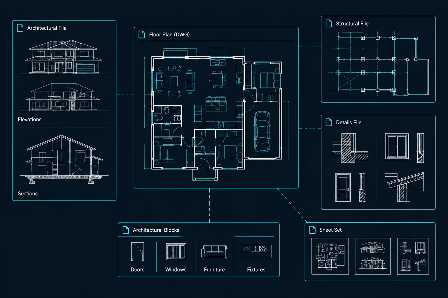
Before drafting, identify which files and documents control the elevation. The architectural floor plans normally establish wall locations, openings, and major projections. Building sections and level information control vertical placement. Roof plans clarify slopes, parapets, edges, and drainage-related forms. Door and window information helps verify opening types and identifiers.
Useful source information may include:
- Current floor plans for every level visible in the elevation
- Building sections with coordinated vertical references
- Roof plans and relevant roof details
- Door and window schedules or type drawings
- Exterior material design decisions and transition locations
- Structural backgrounds where framing affects exposed geometry
- Site or grading information near the building perimeter
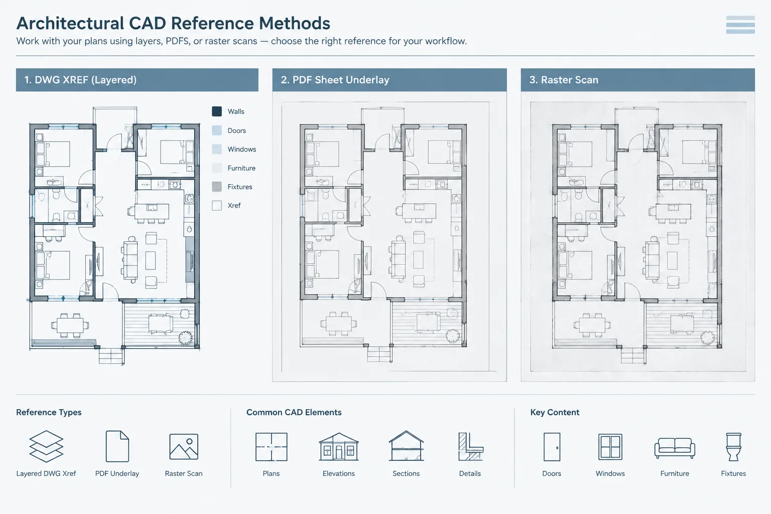
Use current reference files rather than copied fragments whenever the project workflow permits. A copied plan can quickly become outdated, while an external reference can be reloaded when the source changes. Confirm the project origin, units, and orientation before projecting any geometry.
Establish horizontal and vertical controls
An exterior elevation needs references that remain stable while the design changes. In the horizontal direction, use grids, major wall faces, building corners, and opening centerlines where appropriate. In the vertical direction, establish project levels, roof datums, parapet references, and grade information based on coordinated project data.
Place temporary projection lines on dedicated nonplotting layers or another clearly controlled construction layer. Extend important plan references into the elevation work area, but do not allow temporary geometry to become indistinguishable from finished linework.
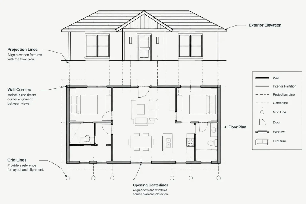
Level references should be shared with sections rather than independently estimated. If an elevation and section show the same floor, roof, or parapet, both drawings should derive that position from the same project information. A mismatch is usually a coordination problem, not a graphic problem.
Build the elevation from major forms to smaller elements
Outline the primary building mass
Begin with the overall visible silhouette: exterior wall limits, major roof edges, parapets, foundations exposed above grade, canopies, and large recesses or projections. This establishes the building mass before detailed components make the drawing visually busy.
Check corners against the plan. A wall that is prominent in one elevation may appear only as an edge in the adjacent view. Consistent corner locations help prevent elevations from depicting incompatible building depths.
Project doors, windows, and other openings
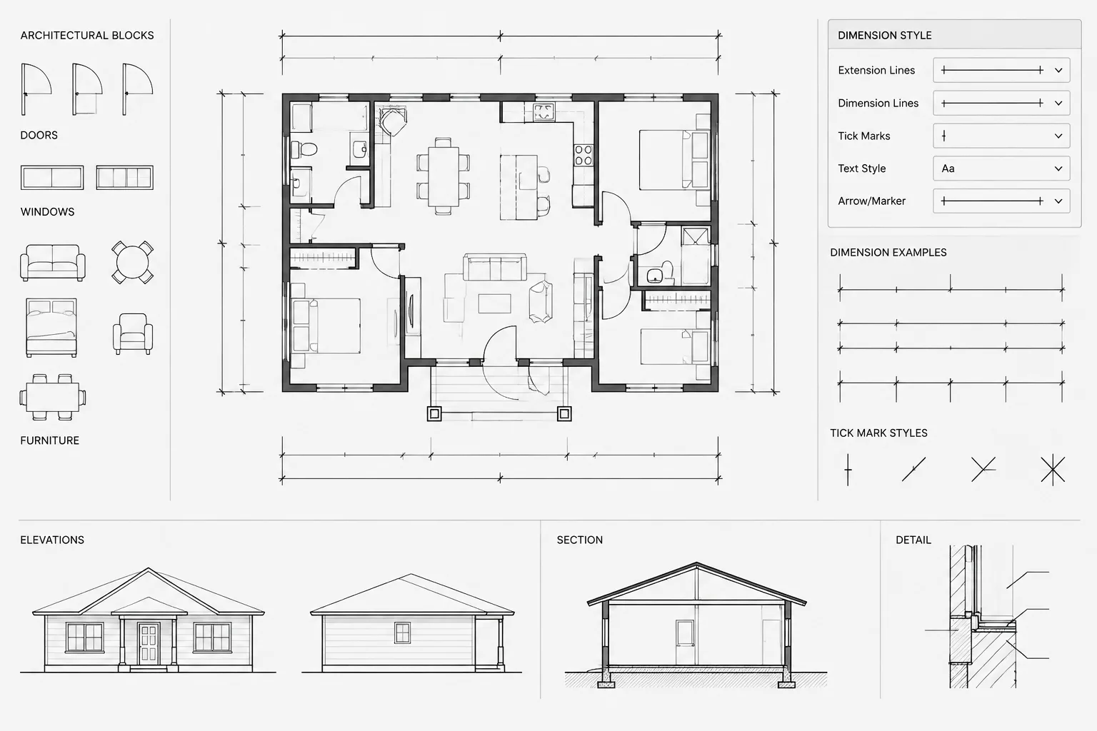
Transfer opening locations from the plans using wall faces, grids, or other dependable references. Then use the coordinated vertical information to establish heads, sills, thresholds, transoms, and related components. Do not infer every opening from a repeated block unless the type and location have been verified.
Differentiate between the rough wall opening, visible frame, operable panel, glazing division, and trim only to the extent required by the drawing scale and purpose. Excessive component detail can make a general elevation harder to read and more difficult to update.
Add roof and projected elements
Coordinate visible roof geometry with the roof plan and sections. Include roof edges, ridges, eaves, parapets, penthouses, screens, chimneys, and equipment only when they are visible or necessary for coordination. Elements behind the primary elevation plane may require lighter or dashed representation according to the office graphic convention.
Canopies, balconies, sunshades, exterior stairs, guardrails, and similar projections should be checked in both plan and section. Their width comes from plan information, while their elevation and depth often depend on sections or details.
Represent grade carefully
Show the building’s relationship to adjacent grade using verified site or grading information. Avoid drawing a decorative ground line that conflicts with actual design data. Where the grade varies significantly, coordinate the elevation with the civil or landscape background and clarify which features are existing or proposed.
Use a lineweight hierarchy instead of equal-weight outlines
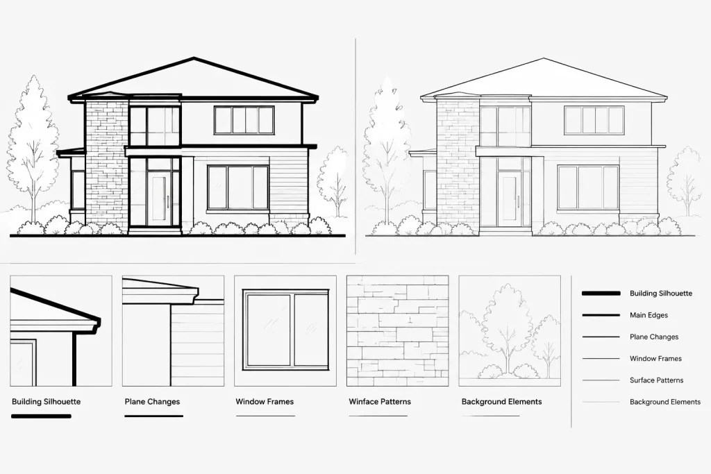
Exterior elevations are easier to read when lineweight communicates depth and importance. The exact plotted weights depend on the project template and office standards, but the hierarchy should remain intentional.
| Graphic category | Typical purpose | Drafting approach |
|---|---|---|
| Primary silhouette | Defines the overall building form | Use the strongest visible outline appropriate to the sheet |
| Major plane changes | Shows recesses, projections, and depth | Use clear but subordinate visible lines |
| Openings and components | Identifies doors, windows, panels, and trim | Use controlled medium or light linework |
| Surface patterns | Suggests material, module, or texture | Keep lighter than object edges and annotations |
| Beyond or hidden information | Provides limited context | Use lighter or alternate linetypes only when useful |
Do not rely on color alone to judge the result. Review plotted output or a PDF using the actual page setup and plot style. Dense material patterns, glazing lines, or copied consultant geometry can overpower the main building form even when the model-space colors appear organized.
Control material patterns and façade modules
Material indication should help explain the façade rather than simulate a photograph. Use hatches, line patterns, joints, or limited notes to distinguish relevant materials. Keep patterns associated with their intended boundaries where practical, and inspect them at the final plotting scale.
For repeated panels, masonry modules, siding, louvers, or glazing grids, establish a logical control point. Coordinate the pattern with corners, openings, datum lines, and major joints rather than filling each surface independently. If a module is conceptual rather than construction-controlled, avoid presenting it with misleading precision.
Large hatch boundaries can become difficult to edit. Dividing patterns at real material transitions or building breaks may improve file stability and make future revisions easier. Avoid exploding patterns merely to change their appearance unless the downstream editing consequences are understood.
Coordinate tags, levels, and notes
Annotations should identify information without obscuring the façade. Common elevation content includes level markers, door and window identifiers, material references, keynotes, section or detail references, and labels for significant building features.
Keep tag placement systematic across related elevations. Leaders should point to unambiguous targets and should not cross important profiles unnecessarily. Material notes should distinguish adjacent surfaces clearly, especially where a transition is shown only by a light line or pattern change.
Use a consistent annotation strategy for model space and paper space. If annotative objects are part of the office workflow, verify that all required scales are assigned and that duplicate representations are not appearing in viewports.
Coordinate adjacent elevations at corners
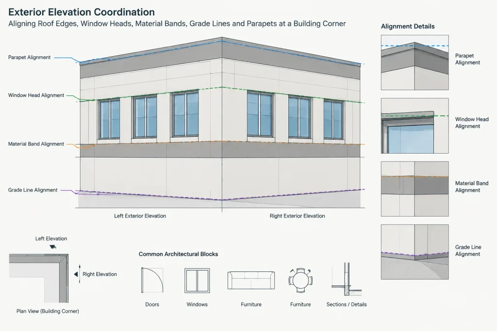
Building corners are common locations for inconsistencies. Compare adjacent views and confirm that these items turn the corner correctly:
- Roof edges, parapets, copings, and eaves
- Material bands and horizontal joints
- Window heads, sills, and glazing divisions
- Canopies, balconies, railings, and projections
- Grade lines and exposed foundation conditions
- Vertical joints, downspouts, screens, and trim
A useful review technique is to place related elevations near one another temporarily in model space or on a coordination sheet. Extend temporary level lines across them and compare repeated features. Remove or freeze those construction lines before publishing the final sheets.
Manage revisions without redrawing the elevation
When the plan changes, identify which elevation references are affected before editing finished graphics. A moved exterior wall may alter the silhouette, roof edge, openings, material extents, and dimensions. A changed window may affect its tag, schedule entry, wall pattern, head condition, and nearby detail references.
Keep revised geometry on its proper object layers rather than placing all changes on a general revision layer. Revision markup can identify the change area, but the permanent drawing objects should continue to follow the project’s layer and property system.
Perform a final coordination review
Before issue, review each elevation at both close range and its intended sheet scale. The close review finds disconnected lines, hatch leaks, duplicate objects, and incorrect trim conditions. The sheet-scale review reveals weak hierarchy, crowded notes, and patterns that merge into dark areas.
- Compare wall limits and openings with current floor plans.
- Compare levels, roof geometry, and projections with sections.
- Verify door and window identifiers against coordinated project information.
- Check material transitions at corners and around openings.
- Confirm that grade information matches the current site design.
- Review lineweights, linetypes, hatch density, and draw order in plotted output.
- Remove unused construction geometry and resolve visible reference errors.
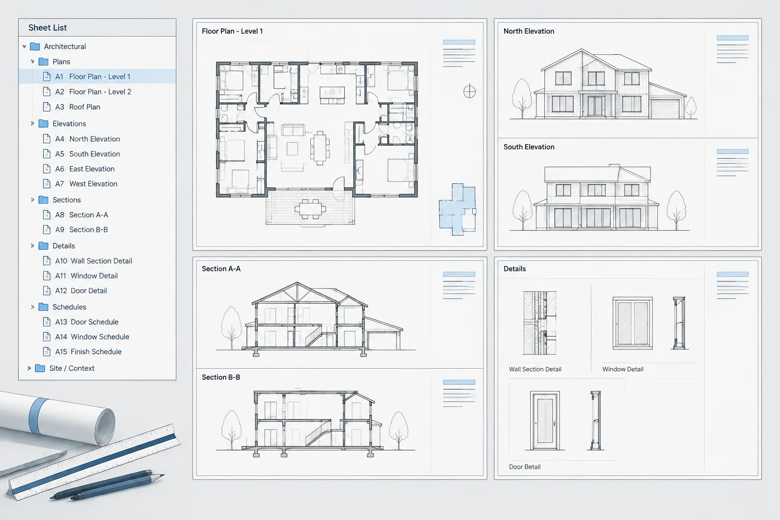
- Confirm that titles, elevation identifiers, and callout references agree with the sheet set.
A successful exterior elevation is not simply a traced façade. It is a coordinated view that translates plan and section information into a clear vertical drawing. By using stable references, disciplined layers, controlled graphic depth, and repeatable checks, CAD users can produce elevations that remain readable and manageable as the project develops.
Turn coordination into a repeatable review process
A strong elevation workflow distinguishes between source information, derived geometry, and presentation graphics. Source information includes the plans, sections, schedules, roof information, and site data that control the drawing. Derived geometry includes projected corners, openings, levels, and roof edges. Presentation graphics include lineweights, hatches, notes, tags, and other elements used to communicate the coordinated result.
Keeping these categories clear makes revisions easier to diagnose. If an opening is misplaced, first determine whether the plan reference, vertical control, or elevation graphic is incorrect. Editing the visible outline without resolving its controlling information can hide a conflict rather than correct it.
Use an exception-based coordination log
Not every discrepancy can be resolved immediately. Questions about grade, roof visibility, material transitions, opening types, or consultant geometry can be recorded as coordination exceptions. Each exception should identify the affected view, the conflicting source information, and the decision needed. This keeps uncertain conditions visible without allowing assumptions to become permanent drawing content.
Review by building feature, not only by sheet
Sheet-by-sheet review can miss conflicts that cross drawing boundaries. A feature-based review follows the same element through every relevant view. For example, a canopy can be checked against its plan extent, elevation position, sectional depth, supporting geometry, material note, and detail reference. The same method works for parapets, façade joints, window groups, balconies, screens, and grade transitions.
Separate design completeness from graphic completeness
An elevation may look polished while still containing unresolved design information. Conversely, a coordinated view may need additional graphic refinement before publication. Review these conditions separately:
- Design coordination: Confirm that visible forms, openings, levels, materials, and site relationships agree with their controlling information.
- Drawing coordination: Confirm that identifiers, notes, references, and repeated features agree across the document set.
- Graphic communication: Confirm that silhouettes, plane changes, surface patterns, and annotations remain legible at the intended output scale.
- File management: Confirm that references, layers, object properties, and temporary construction geometry are organized for later revisions.
This separation helps reviewers explain whether a problem is geometric, informational, graphic, or file-related. It also reduces unnecessary redrafting when the underlying issue belongs in another source drawing.
Frequently Asked Questions
Should an exterior elevation be traced directly from a floor plan?
A floor plan is an important horizontal reference, but it does not provide all of the information needed for an elevation. Vertical locations should be coordinated with levels and sections, while roof forms, grade, opening types, and projected elements may depend on other project information.
Why should projection lines be kept separate from finished elevation linework?
Separate construction geometry makes it easier to distinguish temporary alignment aids from publishable objects. It also allows projection lines to be hidden, revised, or removed without disturbing the finished façade graphics.
How can adjacent exterior elevations be checked at building corners?
Compare shared corner locations, roof edges, material bands, opening alignments, projections, and grade conditions. Temporary common level lines can help reveal differences between related views before the drawings are prepared for issue.
When should material hatches be added?
Add material patterns after the main geometry and transition boundaries are stable enough to control them. Patterns should support material identification without overpowering silhouettes, openings, notes, or important plane changes.
What should be checked after a plan revision?
Trace the effect of the revision through the elevation rather than changing only the most obvious outline. Review associated openings, roof edges, material extents, annotations, schedules, and detail references wherever the revised plan geometry affects them.
Can an exterior elevation be considered coordinated because it looks complete?
No. Visual completeness does not confirm agreement with plans, sections, roof information, schedules, or site data. Coordination requires comparison with the current controlling sources and review of the plotted drawing.