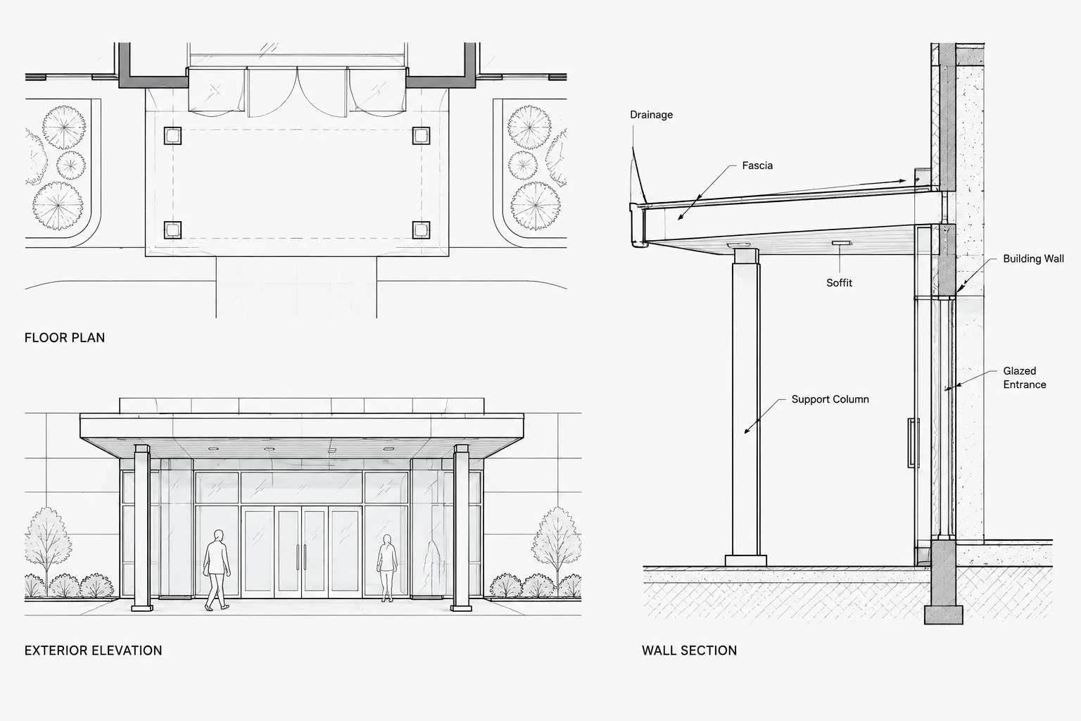
Entrance canopy CAD drafting requires more than adding an overhead outline to a floor plan or a projecting form to an elevation. The canopy must remain consistent wherever it appears, while its supports, edges, soffit, drainage intent, signage, lighting, and wall interface must align with the surrounding architecture.
This guide presents a view-based coordination workflow for canopies and awnings. It focuses on how architectural drafters can establish dependable reference geometry, communicate design intent, identify unresolved work, and reduce conflicts between plans, elevations, sections, details, and consultant backgrounds.
Entrance canopies and awnings may look simple in an exterior elevation, but they often involve several overlapping drawing concerns. Their footprints affect site and floor plans, their edges influence building elevations, and their connections require coordination with wall assemblies, structure, drainage, lighting, signage, and door operation.
A reliable entrance canopy CAD drafting workflow therefore treats the canopy as a coordinated architectural element rather than a decorative outline added near the end of the project. The goal is not to design structural connections or drainage systems without consultant input. It is to create clear architectural geometry that establishes design intent, supports coordination, and can be updated consistently across views.
Begin with the Canopy’s Design Intent
Before drawing detailed geometry, identify what the canopy is expected to do. An entrance canopy may mark an entry, provide limited weather protection, support signage, cover a drop-off area, or create a transition between exterior and interior spaces. An awning may be attached to a storefront, window, service opening, or secondary entrance.
Record the information that controls its representation:
- Location relative to doors, glazing, columns, and wall openings
- Overall footprint and projection
- Top, underside, and edge elevations
- Whether the assembly is level, sloped, curved, or faceted
- Wall-mounted, column-supported, suspended, or combined support
- Visible fascia, trim, gutters, downspouts, or scuppers
- Integrated lighting, signage, cameras, speakers, or other equipment
- Required consultant information that has not yet been resolved
Do not infer structural capacity, attachment requirements, drainage performance, or required clearances from a generic CAD detail. Mark unresolved items for coordination rather than presenting assumptions as completed design decisions.
Establish a Shared Geometric Reference
Use stable project geometry to locate the canopy. Building grids, wall faces, opening centerlines, column lines, and established floor levels are more dependable than isolated dimensions to unrelated objects.
For a canopy centered over an entrance, decide whether its controlling reference is the door opening, storefront bay, vestibule, structural grid, or architectural composition. These references may not share the same centerline. Making the controlling relationship explicit helps prevent small shifts between the plan and elevation.
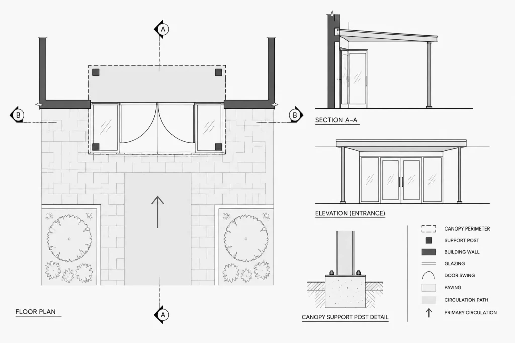
Keep the primary canopy outline easy to edit. Avoid rebuilding the same footprint independently in every drawing. Depending on the project structure, the controlling geometry may be maintained in a referenced base drawing, a reusable block, or a clearly identified source view. Derived views should be checked whenever that source changes.
Draft the Canopy in Plan
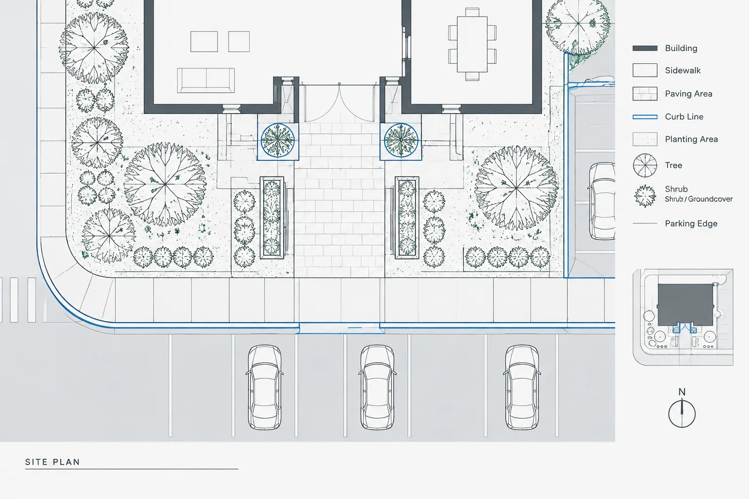
The floor plan should show how the canopy relates to circulation, walls, doors, columns, and exterior paving. Because the canopy is commonly above the floor-plan cut plane, its outer edge is often represented as overhead geometry rather than as a cut object. The exact graphic treatment should follow the project’s drafting conventions.
Include the plan information that affects coordination
- Canopy perimeter and shape
- Wall attachment line or support zone
- Columns, posts, hangers, or other visible supports
- Relationship to door swings and entrance paths
- Nearby curbs, ramps, steps, planters, and site furnishings
- Drainage outlet locations when established
- Limits of soffits or ceiling panels where relevant
- Section and detail references
Check that supports do not conflict with doors, storefront framing, pedestrian routes, vehicle areas, or landscape elements. A support may appear visually balanced in elevation while creating a circulation problem in plan.
Use a distinct overhead linetype and appropriate lineweight so the canopy remains visible without overpowering walls, openings, and primary plan geometry. If both roof edges and soffit edges are shown, give them a clear hierarchy rather than drawing several equally prominent outlines.
Coordinate the Exterior Elevation
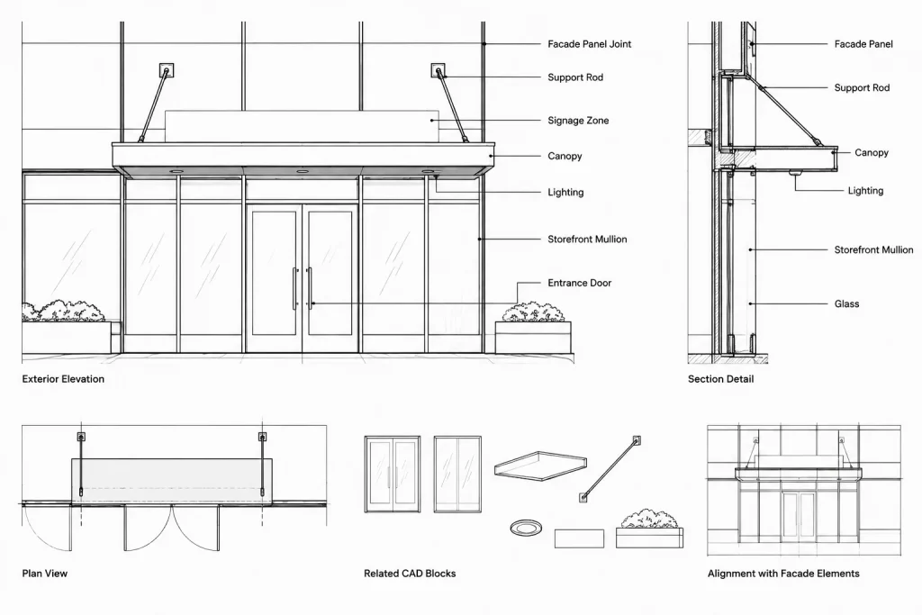
The elevation communicates the canopy’s composition and relationship to the facade. Project the important plan references into the elevation instead of positioning the canopy by eye.
Coordinate the canopy with:
- Door and window heads
- Storefront mullions and structural bays
- Facade joints, panels, masonry coursing, and trim
- Exterior lighting and signage zones
- Building corners and adjacent roof forms
- Columns, rods, brackets, and other supports
Show enough depth to make the assembly understandable. A single horizontal line may be adequate in an early concept drawing, but a developed elevation usually needs a visible fascia, underside, support arrangement, and relationship to the wall.
Be careful when using repeated elevation blocks for brackets or supports. If the canopy width changes, verify that the repeated elements remain aligned with actual structural or facade references. Repetition should simplify editing, not conceal unresolved geometry.
Use Sections to Resolve Projection and Vertical Relationships
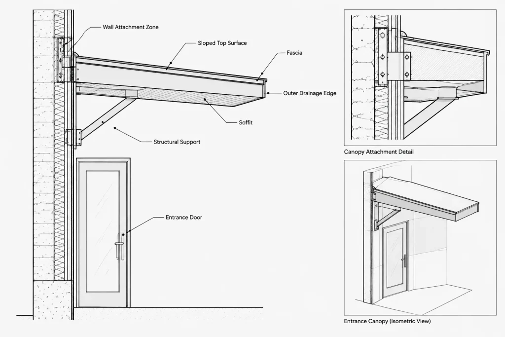
A section through the entrance is often the most useful canopy coordination view. It can show the wall connection, canopy projection, slope, edge condition, underside, support depth, and relationship to the door below.
The section should distinguish architectural intent from consultant design. Architectural drawings can indicate the desired profile, finish zones, drainage direction, and visible support concept. Structural member sizes, reinforcement, anchors, and engineered connections should be coordinated with the responsible design professional.
Include relevant vertical references such as finished floor, exterior grade or paving, opening head, canopy underside, canopy top, and adjacent facade features. Use the same project datums applied elsewhere in the drawing set so elevations can be checked across sheets.
Plan for Water Without Inventing a Drainage Solution
Canopies exposed to weather need a clear water-management concept, but the architectural drawings should not imply a fully resolved system when information is incomplete. Identify whether water is intended to drain toward an edge, gutter, scupper, concealed outlet, or another coordinated collection point.
Review where discharged water would go. Avoid depicting runoff toward an entrance path, door threshold, or area where water could collect. Also consider how gutters and downspouts affect the elevation, wall attachment, landscape, and paving drawings.
If the drainage configuration is pending consultant or manufacturer coordination, use a concise note or coordination marker. Do not copy a generic roof or gutter detail solely because its profile looks similar.
Coordinate Equipment in and Around the Canopy
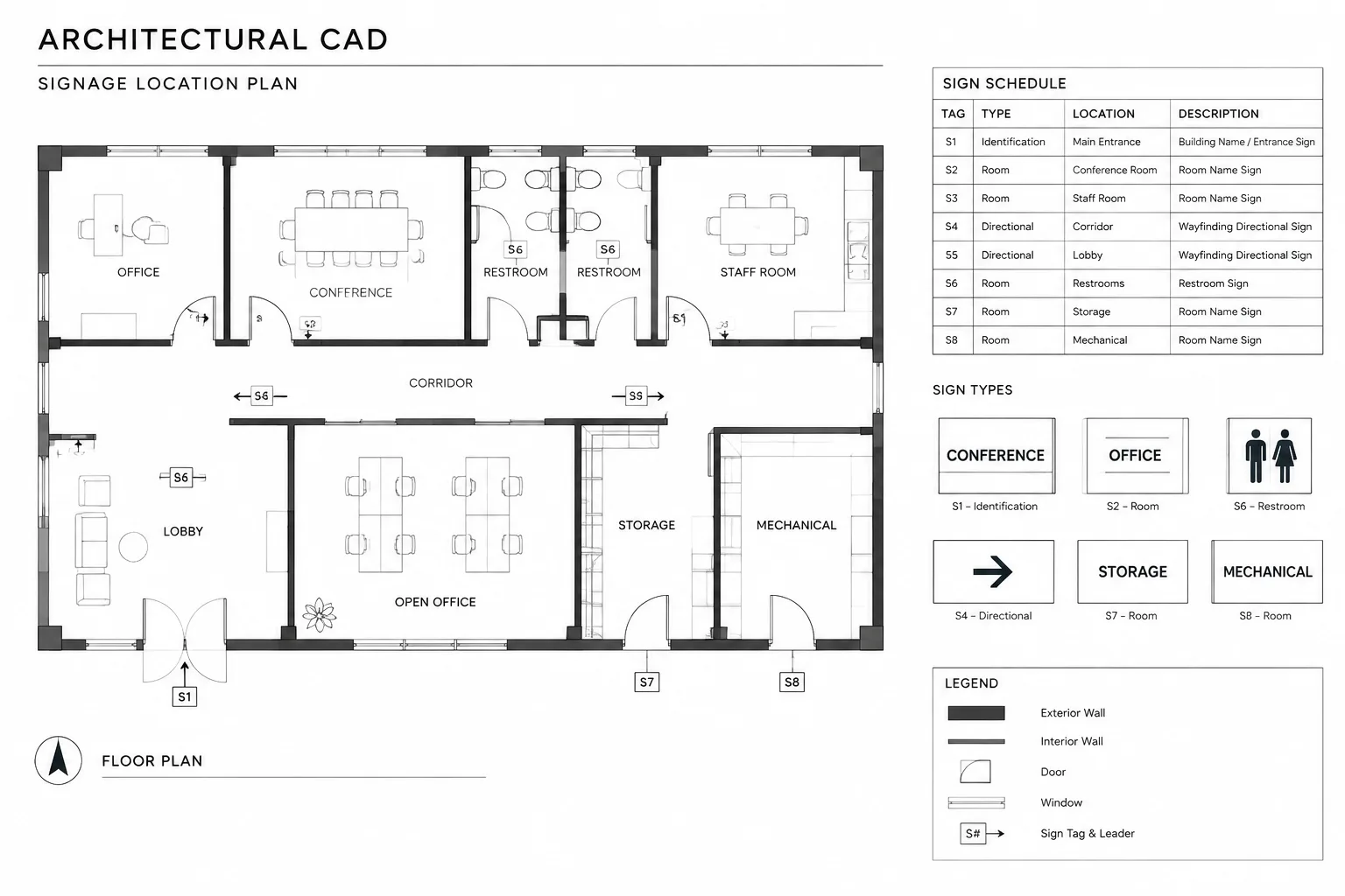
The canopy underside often becomes a crowded coordination zone. Recessed or surface-mounted lighting, exit-related devices, security equipment, speakers, sprinklers where applicable, and signage supports may all compete for limited space.
A reflected canopy or soffit plan can be useful when the underside contains multiple elements. It should share the same perimeter and support references as the architectural plan. Avoid drafting the soffit outline separately without checking it against the canopy edge.
| Element | Primary coordination question | Useful CAD view |
|---|---|---|
| Lighting | Does the layout align with doors, panels, supports, and signage? | Soffit plan and section |
| Signage | Is there sufficient visible area and a coordinated attachment zone? | Elevation and section |
| Drainage | Where is water collected and discharged? | Plan, elevation, and edge detail |
| Structural supports | Do supports align across architectural and structural backgrounds? | Plan, elevation, and section |
| Facade joints | Does the attachment cross or interrupt finish joints? | Elevation and wall detail |
| Door operation | Do supports, fascia, or equipment interfere with the entrance? | Floor plan and entrance section |
Organize Canopy CAD Geometry for Editing
Separate canopy geometry according to function and visibility. The project layer system may distinguish overhead outlines, visible edges, hidden components, supports, drainage, annotation, and consultant backgrounds. The exact names matter less than consistent use and predictable plotting.
Use blocks for genuinely repeated components such as matching brackets or light symbols. Keep unique perimeter geometry editable unless repetition offers a clear project benefit. If a canopy assembly is referenced into several drawings, assign responsibility for updating the source file and avoid making local copies that can diverge.
Use temporary construction geometry to project centerlines and levels between views, then remove or place it on a nonplotting work layer. Stray projection lines can create confusion in plotted details and exported backgrounds.
Reference Details at the Right Locations
Detail callouts should point to actual changes in construction, not simply fill empty space on a sheet. Common locations requiring clarification include the wall attachment, outer edge, internal drain, column base, soffit transition, fascia return, and intersection with adjacent facade systems.
Before reusing a library detail, compare it with the current canopy geometry and specifications. Check the support concept, wall assembly, finish thicknesses, drainage path, and visible edge. A detail should be adapted and verified rather than treated as universally applicable.
Run a Cross-View Quality Check
Before issuing drawings, compare the canopy in every view where it appears:
- Does the plan footprint match the elevation width and section projection?
- Are columns and brackets in corresponding locations?
- Do top and underside elevations agree across drawings?
- Is the slope direction consistent with the drainage concept?
- Do fascia depth and soffit limits match the details?
- Are doors, glazing, signs, lights, and facade joints coordinated?
- Are unresolved structural and drainage items clearly identified?
- Do callout references lead to the correct views?
- Does the canopy remain legible at the intended plotted scale?
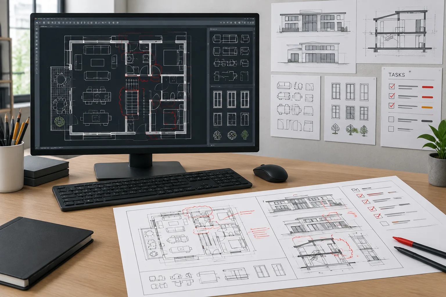
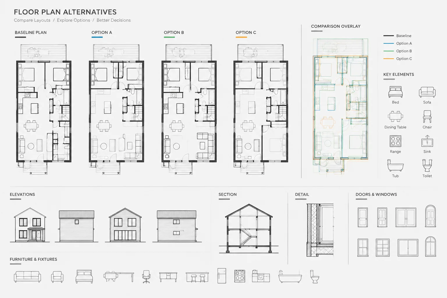
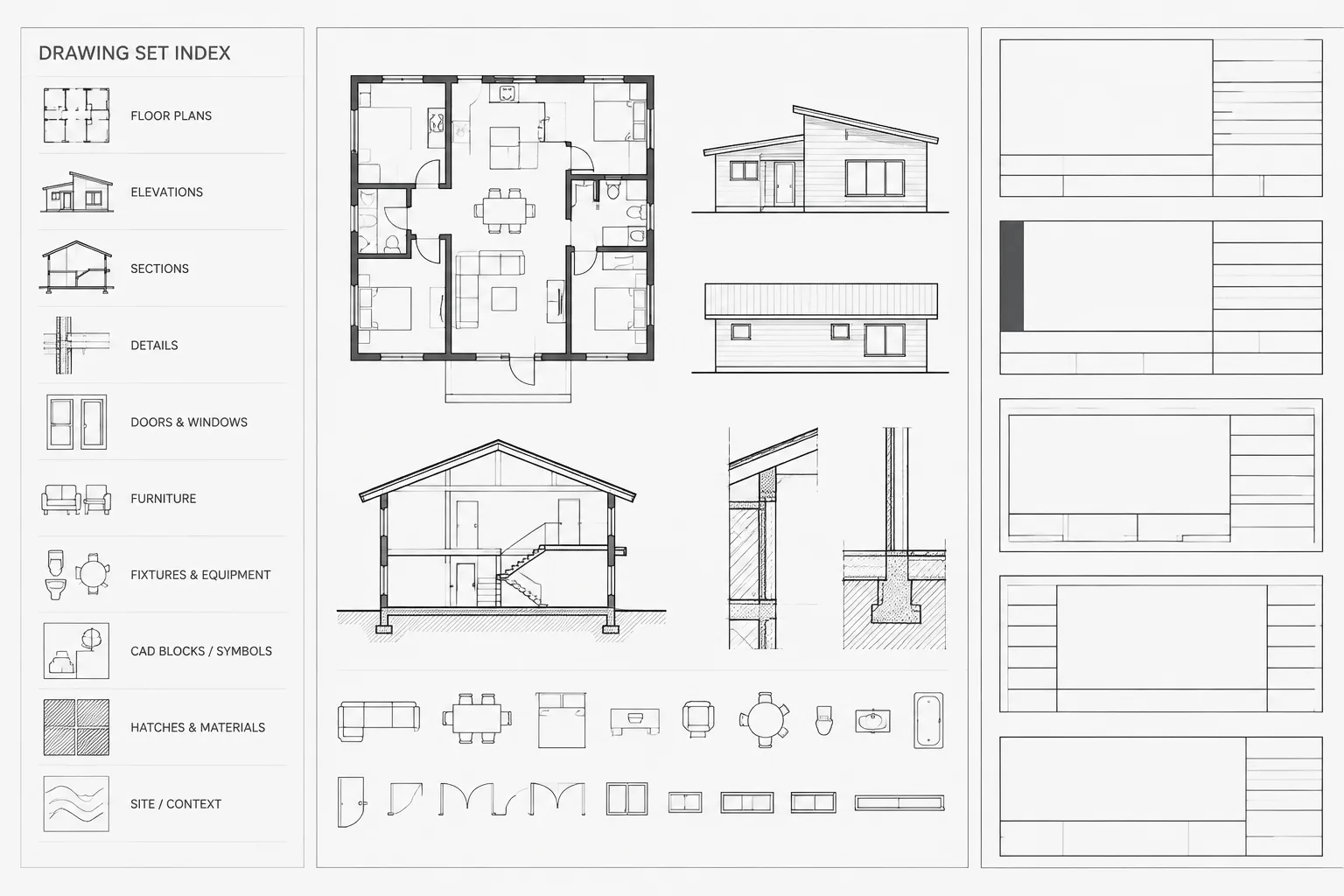
A final overlay or side-by-side review of the plan, elevation, and section can reveal discrepancies that are difficult to notice within a single view. This coordinated approach produces clearer CAD drawings and makes later design revisions easier to manage.
Manage Canopy Revisions Across the Drawing Set
Canopies frequently change as entrance layouts, facade compositions, structural concepts, and equipment requirements develop. Treat a canopy revision as a coordinated drawing-set change rather than a local edit. A modified projection may affect the floor plan, entrance section, exterior elevation, soffit layout, drainage direction, support locations, and related callouts.
When revising the geometry, begin with the designated source view or referenced file. Then review every dependent representation and annotation. Dimensions, levels, leaders, detail markers, hatches, hidden lines, and equipment symbols may not update simply because the main outline changed.
Record unresolved interfaces clearly
Architectural drawings should distinguish established design intent from information awaiting structural, civil, electrical, lighting, signage, facade, or manufacturer coordination. Use the project’s approved notation method to identify pending interfaces. Avoid drawing an apparently complete attachment or drainage assembly when the responsible party has not confirmed it.
Prepare the Canopy for Consultant Backgrounds
Before sharing a background, remove duplicate geometry and confirm that the canopy is located from the same grids, wall faces, centerlines, and levels used in the rest of the project. Include enough context for another discipline to understand the entrance, but avoid unrelated annotation that obscures the coordination area.
Consultant returns should be compared with the current architectural geometry rather than inserted without review. Check whether support lines, equipment locations, penetrations, discharge points, and attachment zones still correspond with the architectural plan, elevation, and section.
Use a Focused Issue Checklist
- Confirm that the current canopy source geometry appears in every affected view.
- Check that overhead, visible, and hidden edges follow the project’s graphic conventions.
- Verify support alignment against entrances, facade modules, paving, and circulation.
- Compare equipment symbols with the soffit limits and support zones.
- Review drainage intent without implying unverified technical design.
- Confirm that notes and callouts identify the correct condition.
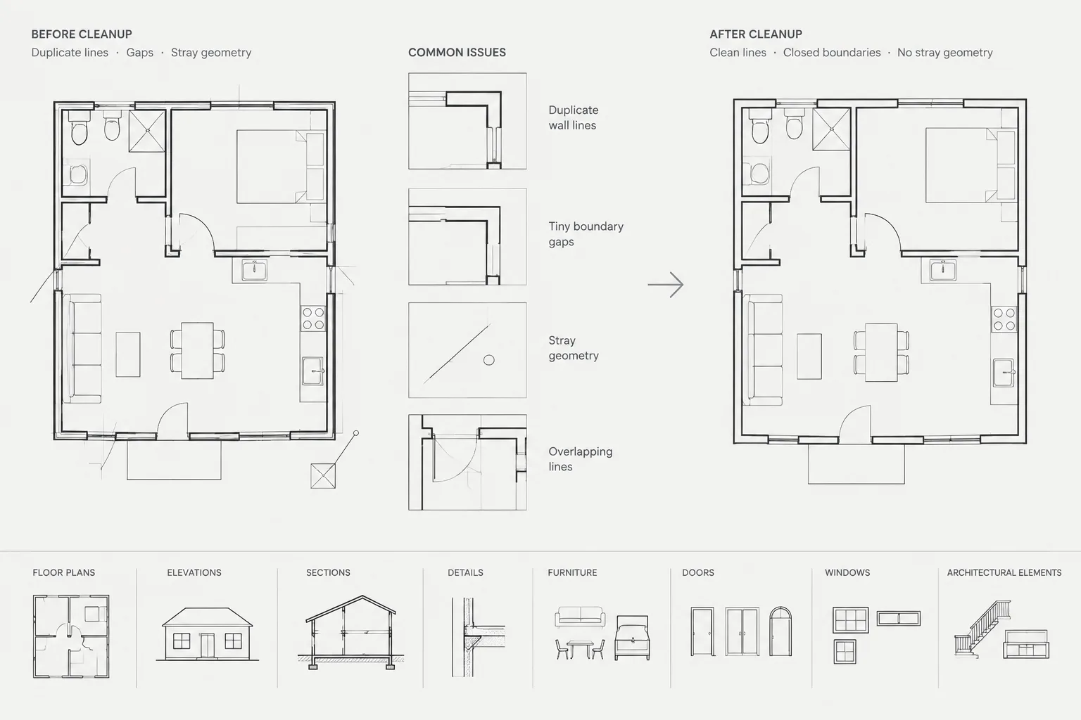
- Remove obsolete linework, abandoned options, and stray construction geometry.
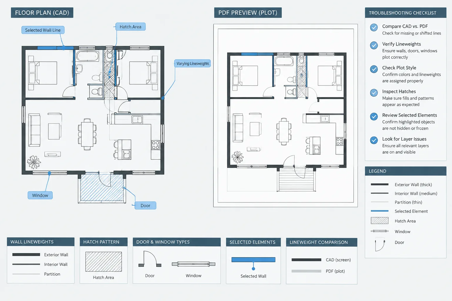
- Plot or preview the affected sheets to verify hierarchy and legibility.
This revision-centered approach helps the canopy remain a coherent architectural element instead of becoming a collection of independently edited lines.
Entrance Canopy CAD Drafting FAQ
What is the difference between drafting a canopy and drafting an awning?
The terms may describe different materials, support concepts, or architectural purposes, depending on the project. In CAD, both require coordinated outlines, attachment references, vertical relationships, and appropriate overhead representation. The drawings should use the terminology established by the project documents rather than assuming the terms are interchangeable.
Should a canopy appear on the floor plan?
It should appear when its footprint, supports, drainage components, or relationship to circulation affects the plan. Because it is commonly above the plan cut, the perimeter is generally represented using the project’s overhead graphic convention.
Which drawing should control the canopy geometry?
The controlling source depends on the project workflow. It may be a referenced plan, a coordinated model-derived view, a reusable assembly, or another clearly assigned source. The important point is to avoid maintaining unrelated versions of the same geometry without a defined update process.
When is a canopy section necessary?
A section is useful when projection, slope, fascia depth, soffit position, wall attachment, support form, drainage intent, or clearance relationships cannot be understood reliably from the plan and elevation alone.
How should unresolved structural connections be shown?
Show the architectural location and visible design intent, then identify the connection as requiring coordination with the responsible design professional. Do not use a generic detail to imply that member sizing, anchorage, reinforcement, or capacity has been verified.
How can repeated brackets or supports be managed efficiently?
Use reusable CAD components when the elements are genuinely identical and share a predictable insertion reference. After any canopy revision, verify each instance against facade joints, structural references, and actual support locations.
What should be checked before a canopy drawing is issued?
Compare the plan, elevation, section, soffit information, details, and consultant backgrounds. Confirm matching geometry, levels, supports, drainage direction, equipment locations, annotation, and callout references, then review the plotted graphics for clarity.