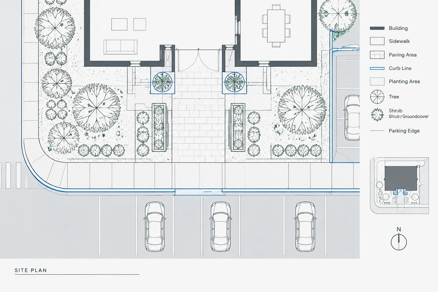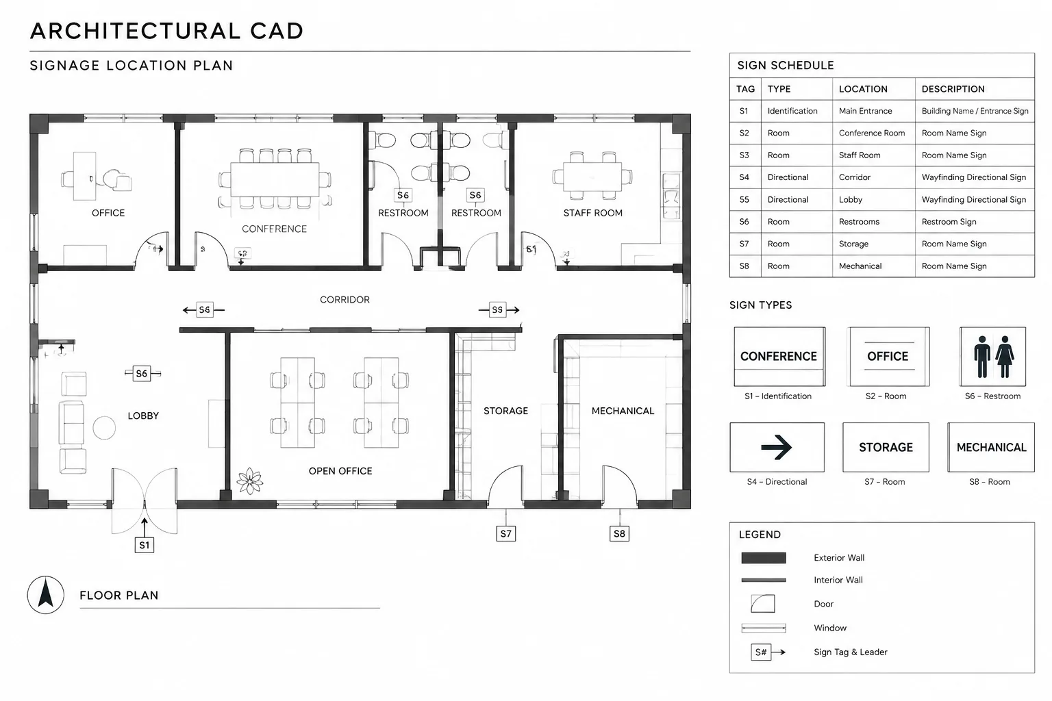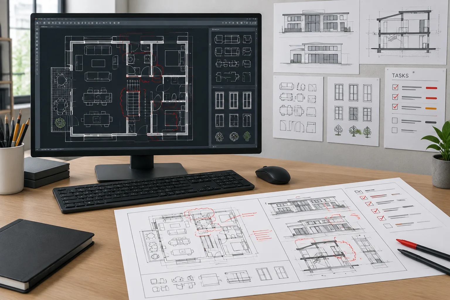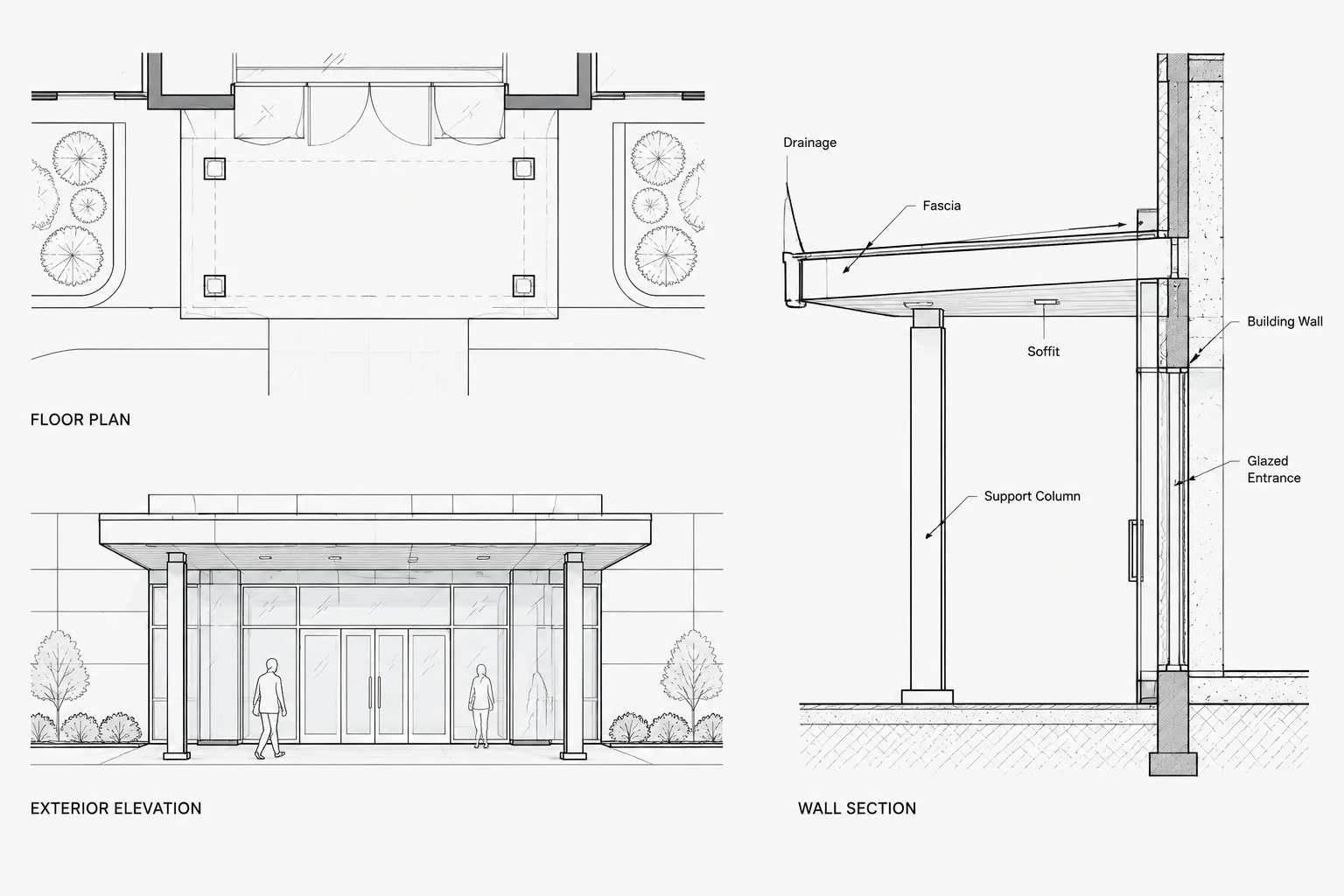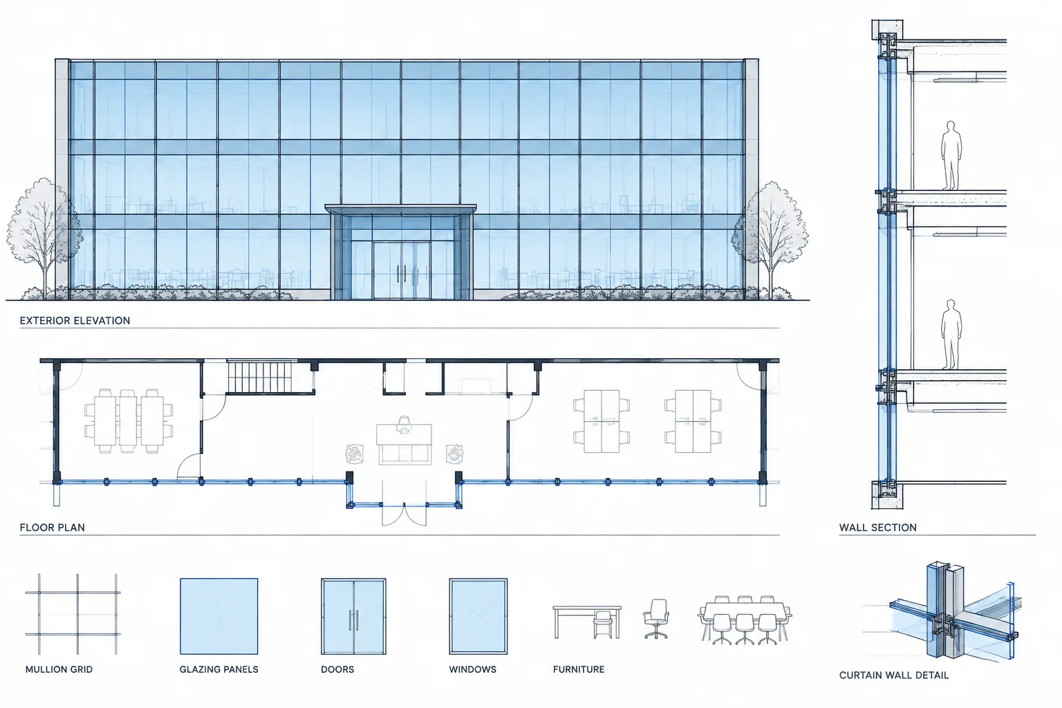
Curtain wall CAD coordination connects facade design with the architectural plans, elevations, sections, details, and schedules used to document a building. A convincing elevation pattern is only one part of the task. The same grid must also respond to structural geometry, interior construction, entrances, ceilings, roofs, and adjacent envelope systems.
This guide explains how to organize curtain wall drawings around shared datums and reference geometry, translate design intent between views, control drawing detail, and identify interfaces that require specialist or manufacturer verification.
Curtain walls can appear simple in an exterior elevation, but a reliable architectural drawing must coordinate much more than a repeated grid of mullions. The system has to relate consistently to floor levels, structural edges, entrance doors, interior partitions, ceilings, parapets, adjacent wall construction, and building-envelope details.
A useful curtain wall CAD workflow therefore begins with reference geometry and system logic rather than individual linework. The goal is not to reproduce every manufactured component in the general drawing set. It is to communicate the design intent clearly, identify important interfaces, and provide a coordinated foundation for specialist drawings and product-specific details.
Start with the information that controls the system
Before drafting the curtain wall, collect the backgrounds and decisions that establish its location. Depending on the project, these may include architectural floor plans, exterior elevations, building sections, structural drawings, reflected ceiling plans, door information, and preliminary system criteria.
Confirm the following before developing the grid:
- The face or reference plane used to locate the assembly
- Floor levels, roof levels, parapets, and major horizontal datums
- Structural slab edges, columns, beams, and transfer conditions
- Locations of entrances, operable units, louvers, and opaque panels
- Transitions to masonry, concrete, framed walls, roofs, and canopies
- Interior partition and ceiling conditions at the facade
- Areas requiring enlarged plans, sections, or interface details
Use verified consultant backgrounds as references rather than redrawing them into the architectural file. This makes later updates easier to identify and reduces the chance of preserving obsolete structural geometry.
Establish a consistent reference plane
A curtain wall can be located by its exterior face, glass line, mullion centerline, system centerline, or another project-defined control plane. Any approach can become confusing if plans, sections, and details use different assumptions.
Choose a reference plane appropriate to the project and document it in the working file. Use that same basis when positioning corners, entrances, returns, and transitions. If the final position remains subject to manufacturer or consultant coordination, label the drawing intent without implying that the system has already been engineered or approved.
A dedicated nonplot construction layer can hold alignment lines, control points, and projection geometry. Keep these aids separate from visible curtain wall linework so they can be reviewed without appearing on issued sheets.
Build the primary grid in elevation
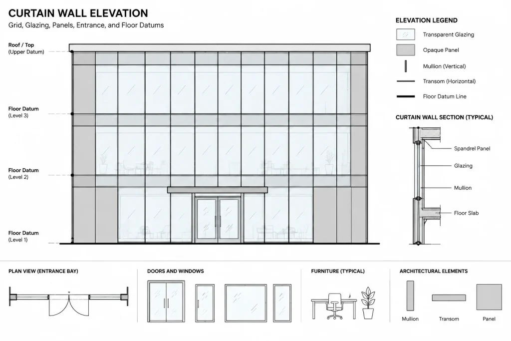
The elevation usually provides the clearest place to establish curtain wall organization. Begin with verified building datums and major facade limits. Add the primary vertical and horizontal grid lines before drawing detailed mullion profiles or panel graphics.
The grid should respond to architectural conditions rather than becoming an arbitrary pattern. Check alignment with:
- Floor and ceiling zones
- Structural bays and column locations
- Door openings and entrance compositions
- Interior rooms and partition intersections
- Spandrel or opaque panel areas
- Facade corners, setbacks, and changes in plane
- Adjacent window, cladding, or wall modules
Repeated bays may be developed with reusable blocks or carefully controlled copied geometry. Avoid turning the entire elevation into one inflexible block if individual bays are expected to change. A modular organization makes revisions easier while preserving alignment.
Differentiate panel types without overloading the elevation
Use restrained graphics to distinguish transparent glazing, opaque panels, louvers, operable units, doors, and other infill conditions. Excessive hatching can hide the mullion grid and make plotted elevations difficult to read.
Panel tags or keyed symbols are often more maintainable than long notes repeated across the facade. The symbols should connect to a coordinated legend, schedule, or specification reference appropriate to the project documentation.
Translate the elevation grid into plan
After the elevation logic is established, project key mullion locations into the floor plans. Plan drawings should show the overall path of the curtain wall, changes in direction, mullion rhythm where relevant, entrance conditions, and relationships to nearby construction.
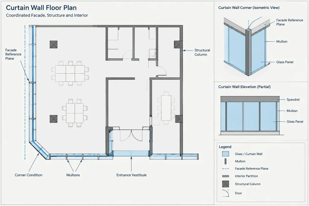
Do not simply draw two parallel lines and assume the system is coordinated. Review what happens where the curtain wall meets:
- Interior partitions
- Perimeter columns
- Exterior wall returns
- Vestibules and entrance doors
- Floor finish transitions
- Built-in furniture or millwork
- Shades, blinds, convectors, or perimeter equipment
At corners, determine whether the design intent uses a corner mullion, butt-glazed appearance, stepped frame, or another configuration. Show only the level of detail supported by the selected system and current design phase. Product-specific corner geometry should be verified against the actual manufacturer’s information.
Use sections to coordinate vertical interfaces
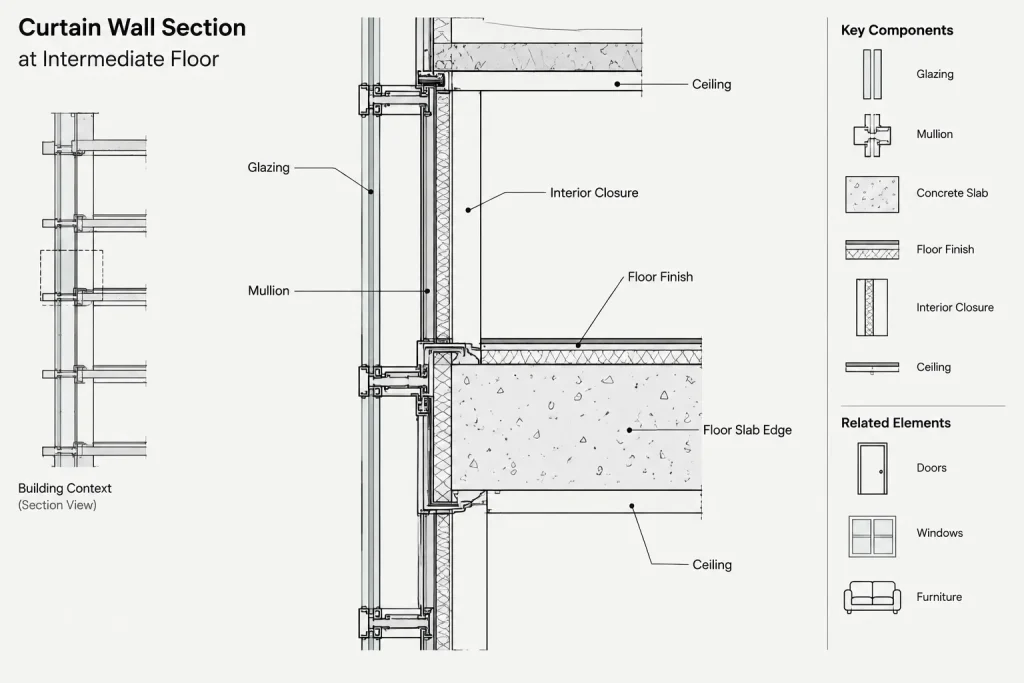
Building sections and wall sections reveal conflicts that may not be visible in plan or elevation. Cut sections through representative sill, intermediate floor, head, roof, parapet, and entrance conditions. Add separate sections where the construction changes rather than forcing several conditions into one generic detail.
Coordinate the curtain wall against the slab edge, structure, ceiling, floor finish, insulation, interior closure, and adjacent envelope assemblies. Draw enough context to show how the architectural systems meet. Highly detailed mullion profiles should come from verified project information rather than being invented from a generic CAD block.
| Drawing view | Primary coordination purpose | Common drafting risk |
|---|---|---|
| Floor plan | Facade path, corners, entrances, and partition interfaces | System location differs from the elevation or detail |
| Exterior elevation | Mullion grid, panel pattern, and facade composition | Grid ignores floors, rooms, or structural conditions |
| Building section | Relationship to levels, floors, roofs, and major structure | Horizontal members do not align with actual datums |
| Wall section | Vertical interfaces and adjacent assemblies | Generic geometry conceals unresolved transitions |
| Enlarged detail | Heads, sills, jambs, corners, and closures | Unverified product geometry is shown as final |
Coordinate doors and operable components
Doors placed within a curtain wall must agree across the plan, elevation, door schedule, and entrance details. Verify leaf configuration, swing, handing notation, frame relationships, hardware coordination, and the surrounding mullion grid. Changes to an entrance width or location can affect adjacent panels and the visual balance of an entire bay.
Operable windows, vents, and louvers should also be distinguishable from fixed panels. Use consistent symbols and confirm that identifiers match schedules or equipment information. Avoid relying on subtle line differences that may disappear when the sheet is plotted or reduced.
Organize curtain wall CAD geometry for revisions
Separate meaningful categories of linework so the system can be edited and displayed at different scales. A project may distinguish primary frames, secondary mullions, glazing, opaque panels, doors, overhead elements, tags, dimensions, and construction geometry. Follow the project layer standard rather than creating isolated naming conventions for one facade.
Blocks are helpful for repeated panel tags, vents, door modules, and typical symbols. Use them carefully when repetition is genuine. If every instance has been edited independently, a block may create more confusion than value. External references can be appropriate when the facade is developed in a separate working file, provided that file ownership, origin, and update procedures are clear.
Control the level of detail
General plans and elevations should communicate organization, not microscopic fabrication. Enlarged sections and details can carry more information, but their geometry must still be based on verified systems and project decisions.
A practical hierarchy is:
- General views show location, extent, grid, and major panel types.
- Enlarged views clarify entrances, corners, transitions, and irregular bays.
- Wall sections show relationships to structure and surrounding assemblies.
- Details resolve specific heads, sills, jambs, anchors, closures, and envelope interfaces.
- Specialist or manufacturer drawings develop fabrication and installation information.
This hierarchy prevents dense general elevations while ensuring that critical interfaces are not left undocumented.
Run a cross-view coordination check
Before issuing the drawings, compare the curtain wall in every relevant view. Trace several representative grid lines through the plan, elevation, and section rather than checking only the overall dimensions.
- Confirm that facade limits and corners occur at the same project coordinates.
- Compare mullion and panel locations with room layouts and partitions.
- Verify that horizontal grid lines agree with floor and roof datums.
- Check entrance configurations against door information.
- Review slab edges, columns, beams, ceilings, and perimeter equipment.
- Confirm that panel tags and symbols match their legends or schedules.
- Inspect transitions to adjacent walls, roofs, canopies, and parapets.
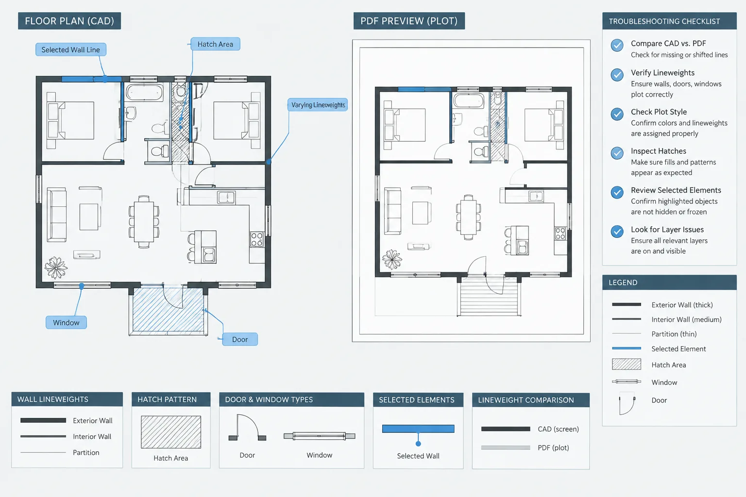
- Plot representative sheets to verify lineweight and panel readability.
Curtain wall CAD drafting works best as a coordinated set of related views, not as an isolated facade drawing. Establishing a stable reference plane, building a logical elevation grid, and deliberately checking interfaces will produce clearer documents while leaving product engineering and fabrication decisions to the appropriate verified sources.
Turn coordination comments into traceable drawing decisions
Curtain wall revisions often affect several drawings at once. When a grid line, entrance, corner, panel type, or facade limit changes, record which plans, elevations, sections, details, tags, and schedules require review. This is more reliable than correcting the view where the issue was first noticed and assuming the remaining documents still agree.
Use drawing references and consistent identifiers to make each condition traceable. A tagged entrance in elevation should lead reviewers to the corresponding plan and detail. A special panel or louver should use the same designation wherever it appears. Clear relationships help expose conflicts before they become embedded in later documentation.
Separate design intent from delegated development
Architectural drawings should define the intended facade location, organization, appearance, interfaces, and performance-related design requirements established for the project. They should not imply that generic mullion shapes, anchors, joints, or internal components represent an approved product assembly.
Where information remains unresolved, show the architectural relationship that must be maintained and identify the item for coordination. Replace placeholder geometry when verified project information becomes available, and review the resulting changes across every affected view.
Review the drawing as a construction interface
A final quality check should ask more than whether the curtain wall looks consistent. Review whether another project participant can understand where the assembly is controlled, how it meets surrounding construction, and which information still depends on specialist development.
- Check whether reference planes and facade limits are unambiguous.
- Confirm that repeated conditions are genuinely identical before using typical details.
- Look for partition, ceiling, floor, roof, and wall interfaces hidden by elevation graphics.
- Verify that notes, tags, and detail references describe the same condition across the set.
- Distinguish verified system information from conceptual or placeholder geometry.
- Record unresolved items so they remain visible during later coordination.
This approach keeps the architectural CAD file useful as the project develops while avoiding unsupported fabrication detail.
Curtain Wall CAD Coordination FAQ
Should the curtain wall grid be drafted in plan or elevation first?
The elevation is often the clearest view for establishing the primary facade pattern, while the plan confirms its path, corners, entrances, and relationships to interior construction. Both views should be developed from shared reference geometry rather than treated as separate compositions.
How much mullion detail belongs in a general elevation?
Show enough information to communicate the grid, major frame relationships, panel types, openings, and design intent. Reserve verified profile geometry and assembly interfaces for enlarged drawings or specialist documentation.
Can a generic curtain wall CAD block be used for project details?
A generic block may support early layout studies or symbolic representation, but it should not be presented as a verified product detail. Project details should reflect confirmed system information and coordinated adjacent construction.
What should be checked when a mullion moves?
Review the related plan, elevation, section, panel identification, entrance composition, interior partition, ceiling condition, structural interface, and any referenced detail. A local graphic adjustment can create conflicts elsewhere in the drawing set.
How should unresolved curtain wall conditions be shown?
Communicate the required architectural relationship and identify the condition for further coordination. Avoid adding invented component geometry that could be mistaken for approved engineering, fabrication, or installation information.
Why are plotted drawing checks important?
Lineweights, glazing graphics, tags, and panel distinctions that appear clear in the working file may become difficult to read on an issued sheet. Reviewing the plotted output helps confirm that the facade hierarchy remains legible.