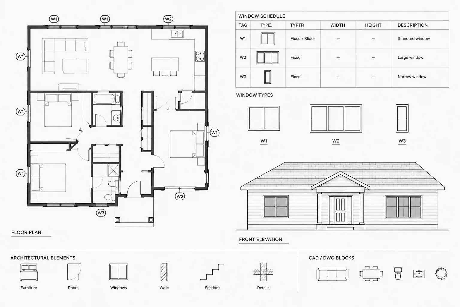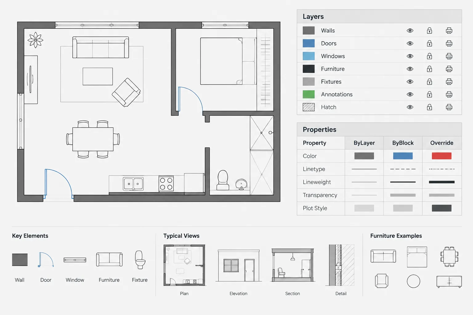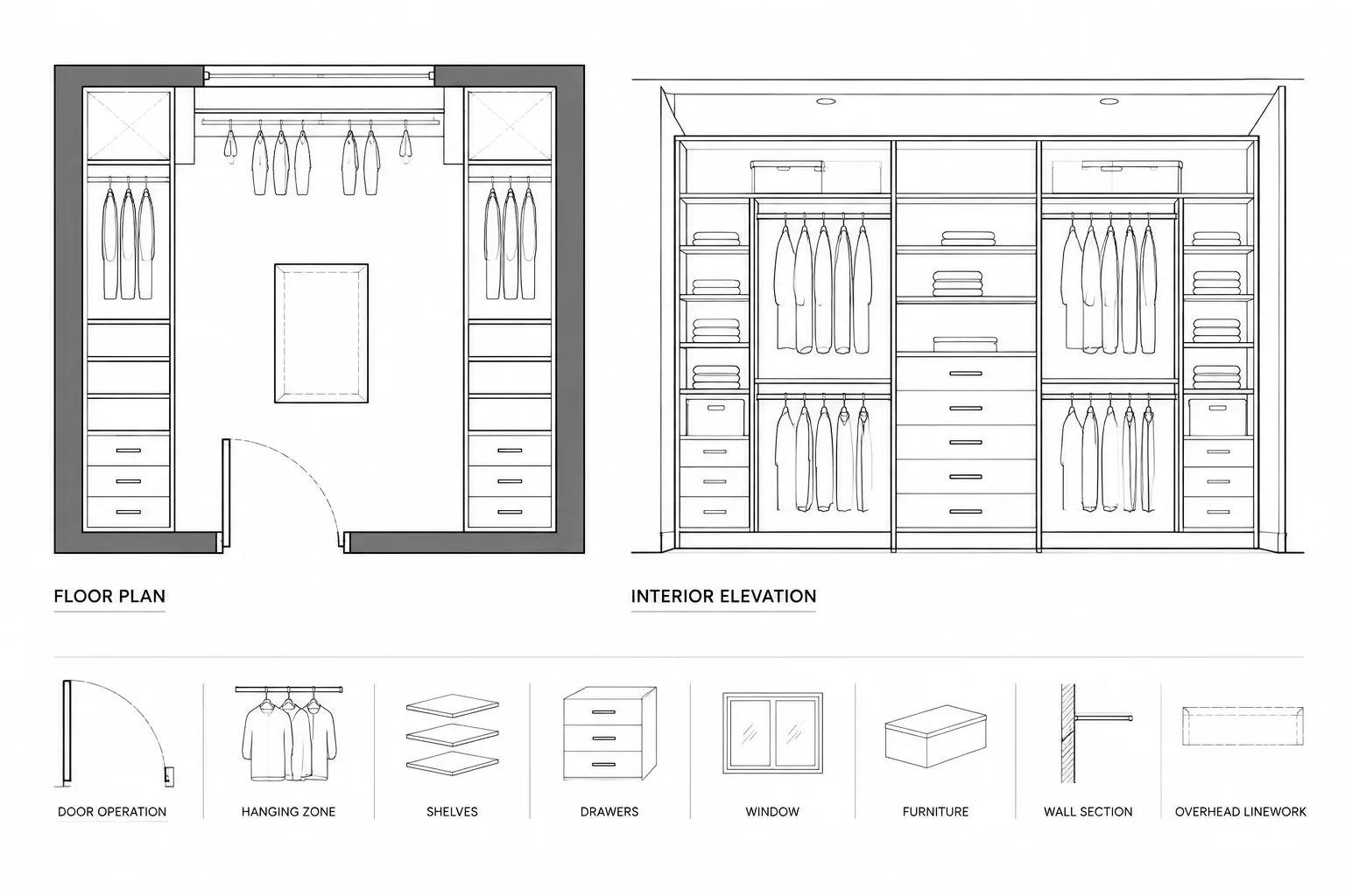
Closet layout CAD work requires more than drawing an enclosure and inserting a shelf symbol. Doors, storage components, finishes, overhead elements, adjacent furniture, and building services all compete for a limited area. A useful drawing must show not only where these elements are located, but also how they are accessed and operated.
This guide presents a coordination-focused workflow for developing closet and built-in storage drawings. It explains what to resolve in plan, when to add interior elevations or sections, how to organize CAD information, and what to review before the drawings are issued.
What a coordinated closet drawing should communicate
- The finished boundaries and accessible opening of the enclosure.
- The type and operation of each door or movable component.
- The distinction between low, high, fixed, adjustable, and movable storage.
- The relationship between plan geometry and vertical storage organization.
- Potential conflicts with trim, furniture, lighting, controls, and building services.
- Clear references between plans, elevations, details, notes, and schedules.
A closet may occupy a small part of a floor plan, but it brings together several elements that can conflict: partitions, doors, shelving, hanging space, lighting, trim, and adjacent furniture. Treating the closet as an empty rectangle with a shelf line often leaves important questions unanswered.
A reliable closet layout in AutoCAD should communicate how the enclosure is accessed, where storage components are located, and whether those components can be used without interference. It should also remain coordinated across plans, interior elevations, sections, schedules, and consultant backgrounds.
The following workflow applies to wardrobes, linen closets, coat closets, utility storage, walk-in closets, and similar built-in storage areas. Actual dimensions and component requirements should always be verified against the project criteria, selected products, applicable regulations, and field conditions.
Begin with the enclosure, not the shelving
Establish the physical boundaries of the closet before adding storage components. Use the architectural wall types, column locations, shafts, and finish faces that define the available space. Do not size the closet from an isolated furniture block while ignoring wall thickness or construction tolerances.
Confirm which faces represent finished surfaces. A shelf or cabinet depth measured from a framing line can produce a misleading amount of usable space once finishes, trim, or wall-mounted equipment are considered.
At this stage, check the relationship between the closet and the surrounding room:
- Identify the primary approach to the opening.
- Review nearby room doors, cabinet doors, and furniture.
- Locate structural projections, plumbing walls, and service chases.
- Determine whether the closet shares a wall with equipment or fixtures requiring access.
- Confirm whether baseboards, casing, or other trim affect the opening or storage components.
These checks prevent the storage layout from being developed in space that is not truly available.
Draft the opening and door operation early
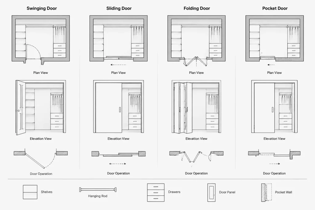
The closet door is one of the strongest constraints on the layout. Place the actual opening and intended door type before arranging shelves or hanging zones. Show enough information to understand how the door moves and what portions of the closet remain accessible.
Swinging doors
For a swinging door, coordinate both sides of the opening. The room-side swing can conflict with furniture, circulation, switches, or another door. The closet-side face can interfere with shelving, drawers, hooks, or stored objects. Include the leaf and swing arc in plan, and verify that casing does not collide with adjacent wall-mounted components.
Sliding and bypass doors
Sliding systems do not require a conventional swing area, but they can restrict access to part of the opening. Draw the overlapping panels clearly enough to show which storage zones may be concealed in each door position. Avoid placing frequently accessed drawers or pull-out components where a panel prevents operation.
Folding and pocket doors
Folding panels occupy space when gathered and may project into the room or opening. Pocket doors require an unobstructed wall cavity and coordination with wall-mounted items, utilities, and backing. Represent the operational condition instead of using a generic door symbol that hides these constraints.
Organize storage by functional zones
Divide the closet into understandable storage zones rather than filling the perimeter with repeated linework. Depending on the project, the zones may include hanging areas, shelves, drawers, cabinets, shoe storage, hooks, luggage storage, or space for movable containers.
Use distinct plan graphics for components with different behaviors. A fixed shelf, hanging rod, full-height cabinet, and pull-out drawer should not all appear as identical rectangles. The drawing should help a reviewer distinguish fixed construction from movable contents and overhead elements.
| Storage element | Useful plan information | Additional view to consider |
|---|---|---|
| Hanging zone | Extent, depth, access side, and relationship to the door | Elevation or section showing rod and shelf arrangement |
| Open shelving | Shelf footprint and whether it is floor-level or overhead | Elevation showing shelf spacing and limits |
| Drawers or pull-outs | Cabinet body and operating direction | Elevation showing drawer stack and adjacent components |
| Full-height cabinet | Overall footprint and door operation | Elevation indicating divisions and top condition |
| Movable storage | Reserved zone rather than permanent construction | Usually unnecessary unless it affects coordination |
Plan for what must move, open, or be reached. The footprint of a cabinet alone does not describe the space needed to use it.
Represent high and low components clearly
Closet plans frequently contain components at several heights. Without a graphic hierarchy, overhead shelves can be mistaken for floor cabinets, and hanging rods can disappear among wall and door lines.
Use the office drafting convention for overhead or concealed elements. This may involve a different linetype, a lighter plot weight, or a specific layer. Apply the convention consistently and explain unfamiliar symbols in a legend or key.
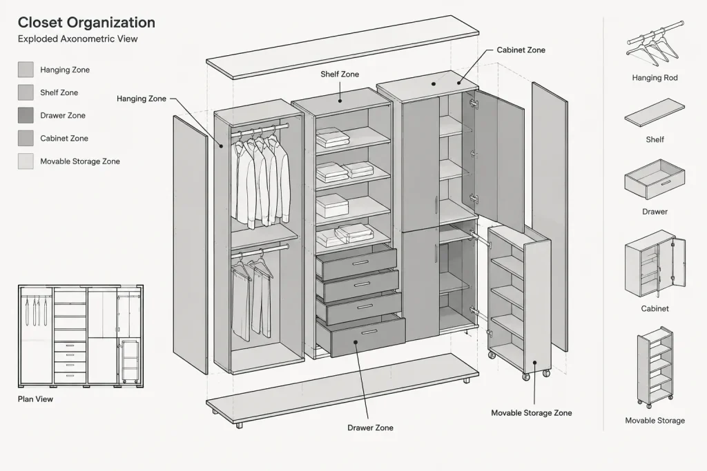
A simple plan may show the location of a shelf and rod, but a more complex storage system usually needs an interior elevation. Add elevations when the vertical organization affects design intent, coordination, fabrication, or installation. Sections are especially useful where sloped ceilings, soffits, beams, stepped floors, or deep wall projections limit the usable volume.
Coordinate clear space and component operation
After placing the storage elements, test the open area between them. Do not evaluate circulation from wall to wall if shelving, hanging garments, handles, or open doors reduce the usable path.
Use temporary clearance outlines on a non-plot layer to study:
- The operating area of drawers and cabinet doors.
- The overlap between hanging storage and the access path.
- The standing area in front of shelves or controls.
- Conflicts between the closet door and internal components.
- The route to storage located at corners or behind door panels.
These outlines are design tools, not automatically construction-document graphics. Remove them or convert them to the project’s approved notation before issuing the drawing.
For a walk-in closet, inspect corners carefully. Two perpendicular hanging zones can overlap physically even when their plan lines appear orderly. Likewise, deep storage placed on opposing sides can leave an impractical central space. Use elevations or sections to verify conditions that are ambiguous in plan.
Check lighting, power, and building services
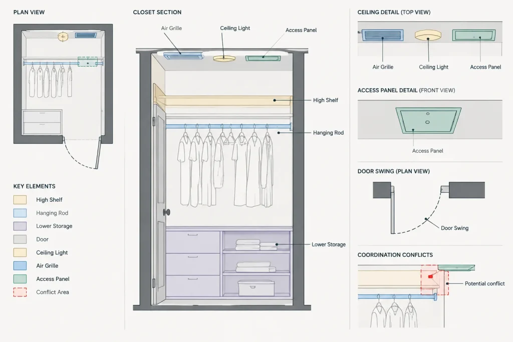
Closets are commonly affected by consultant work even when the architectural plan appears simple. Overlay the relevant backgrounds and review the actual occupied volume, including high shelves and full-height cabinets.
- Confirm that light fixtures are not obstructed by tall storage components.
- Coordinate switches, receptacles, controls, and sensors with shelving and door casing.
- Review sprinkler heads, diffusers, grilles, and access panels where they occur.
- Keep required equipment access areas visible and unresolved conflicts documented.
- Check whether plumbing, ductwork, or structural framing creates a concealed projection.
Do not relocate consultant elements silently in the architectural file. Mark the proposed change, communicate it to the responsible discipline, and update the background when a coordinated location is confirmed.
Use layers and blocks without losing flexibility
Separate enclosure geometry, doors, fixed storage, movable contents, overhead elements, annotation, and temporary clearance studies according to the project layer system. This makes it easier to create clean plans, furniture views, enlarged plans, and consultant backgrounds without deleting information.
Blocks are useful for repeated shelf modules, cabinet units, and common symbols, but avoid making an entire closet a single inflexible block too early. A monolithic block can hide differences between room conditions and encourage unreviewed copying.
When a block is appropriate, give it a meaningful insertion point and confirm its units, layer behavior, linetypes, and nested content. Keep editable project-specific items separate when they are likely to change.
Add only the annotation needed to build and coordinate
Dimension the enclosure and the controlling locations of storage components. Avoid dimensioning every repeated line when a typical note, elevation, or referenced detail communicates the arrangement more clearly.
Useful closet annotation may identify:
- The storage type or closet designation.
- Fixed versus adjustable components.
- Material or finish references.
- Locations coordinated with an interior elevation or millwork detail.
- Items supplied by the contractor, owner, or another party, when defined by the project documents.
Keep notes outside dense geometry when possible, and use leaders that point to a specific component rather than a general area. If the closet belongs in a casework, equipment, or finish schedule, coordinate the identifier instead of creating an unrelated naming system.
Run a focused closet coordination check
Before issuing the drawing, review each closet at its actual sheet scale. A layout that appears clear while zoomed in may become unreadable in the plotted plan.
- Verify the finished enclosure boundaries.
- Confirm the door type, movement, and accessible portion of the opening.
- Check shelves, rods, drawers, and cabinets against the door operation.
- Review overhead elements and vertical conflicts in elevation or section.
- Compare architectural geometry with lighting and service backgrounds.
- Confirm that tags, notes, and dimensions match related schedules and details.
- Remove obsolete options, duplicate blocks, and temporary study geometry.
- Plot or preview the sheet to inspect lineweight, linetype, and text clarity.
A coordinated closet drawing does more than show that storage exists. It explains how the enclosure is entered, how its components operate, and how the plan relates to vertical and consultant information. That level of clarity makes even a compact storage area easier to review, document, and construct.
Build a clear coordination trail
A closet may appear on several drawings, but those views should describe one coordinated condition. Use consistent room names, closet designations, component tags, and elevation references so reviewers can move between the floor plan and supporting views without interpreting conflicting labels.
When the design changes, identify which view controls the affected information. A revised door can alter accessible storage zones, while a revised ceiling condition can affect high shelves or cabinets. Updating only the most visible plan may leave elevations, schedules, or consultant backgrounds out of date.
Separate design studies from issued information
Temporary swing studies, access outlines, alternate shelf arrangements, and consultant markups are valuable during design. Keep them distinguishable from construction-document geometry through the project layer and plotting conventions. Before issue, remove abandoned options and verify that non-plot studies have not become the only record of an important requirement.
Review the closet from the user side
A final CAD check should follow the sequence in which the storage will be approached and used. Start outside the enclosure, pass through the opening, and then consider each door, drawer, shelf, hanging zone, control, and access panel. This perspective often reveals conflicts that are easy to miss when reviewing isolated linework.
Warning signs that another drawing view is needed
- Several storage elements overlap in plan but occur at different heights.
- A door symbol conceals shelving, drawers, or cabinet operation.
- A soffit, slope, beam, or projection changes the usable storage volume.
- Notes are being used to explain a condition that would be clearer in elevation.
- Consultant elements occupy the same wall or ceiling area as storage components.
- Installers would need to infer vertical relationships from plan graphics alone.
Adding a focused elevation or section is often clearer than forcing more notes and linework into the floor plan. The appropriate view depends on the information needed for coordination, fabrication, installation, and review.
Closet and storage CAD FAQs
What should be drawn first in a closet layout?
Begin with the finished enclosure, opening, door operation, and surrounding room conditions. Storage components should be fitted to the verified architectural boundaries rather than used to define those boundaries.
When does a closet need an interior elevation?
Add an interior elevation when vertical relationships cannot be understood reliably in plan. Typical reasons include stacked shelves, hanging components, drawers, full-height cabinets, overhead storage, finish transitions, or coordinated wall-mounted devices.
Should closet clearance outlines appear on the final plan?
Clearance and operating outlines can be useful design tools, but they do not automatically belong on an issued drawing. Follow the project documentation convention and retain only the graphics or notation needed to communicate the final condition clearly.
Is it better to use blocks or draw each storage component separately?
Blocks work well for genuinely repeated modules and symbols. Keep changing or condition-specific components editable, and avoid combining the entire closet into one block if doing so makes coordination or revision difficult.
How should overhead closet elements be shown?
Use the project convention for elements above the plan cut or otherwise concealed. A coordinated linetype, lineweight, layer, and legend can distinguish overhead shelves or cabinets from floor-level components without overcrowding the plan.
How can closet drawings be coordinated with consultants?
Overlay current consultant backgrounds and compare storage with fixtures, controls, devices, access panels, and other services. Proposed relocations should be communicated to the responsible discipline rather than changed only in the architectural file.