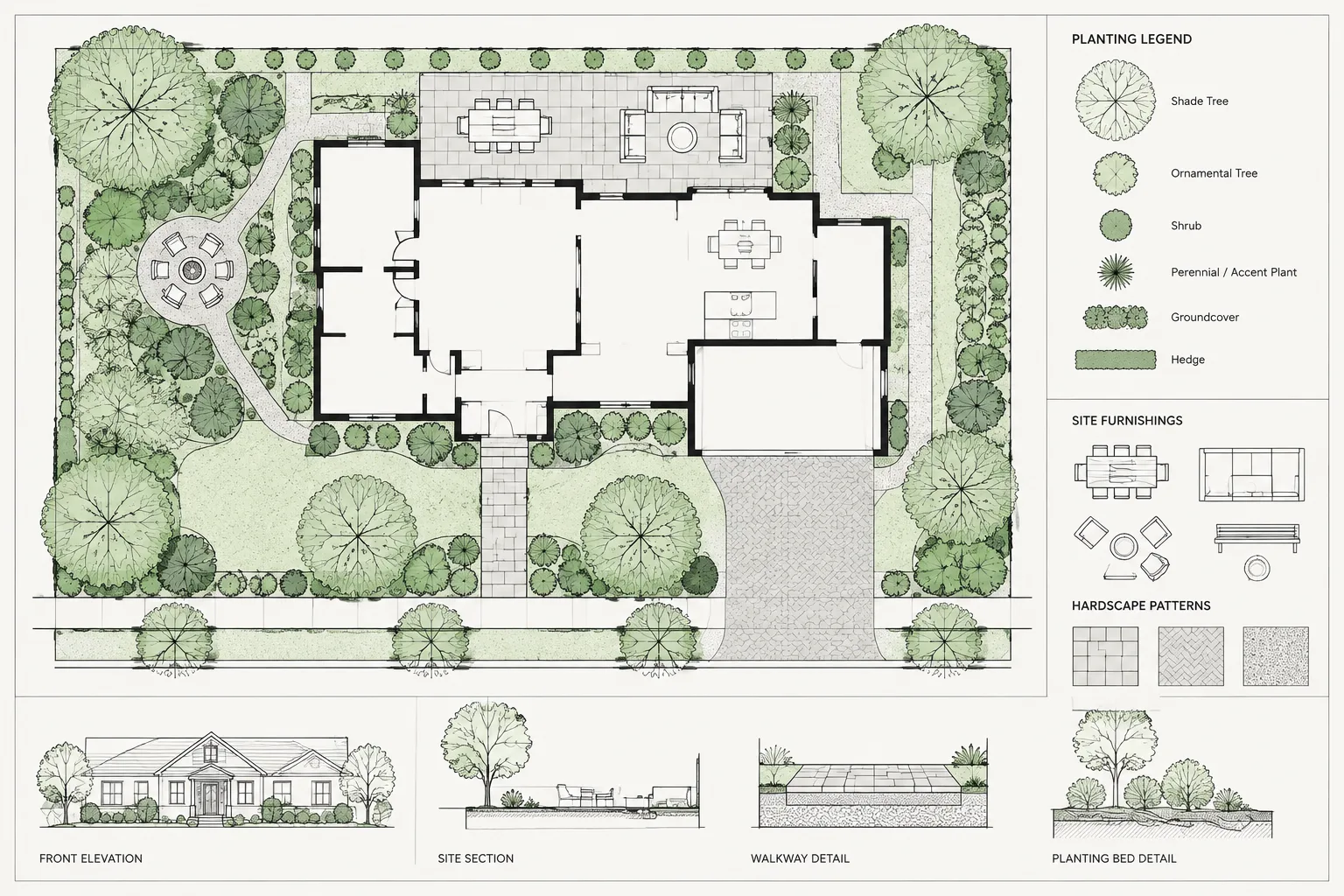
Drafting a landscape plan in architectural CAD requires careful control of source information, drawing ownership, graphic hierarchy, and revisions. The goal is not simply to create an attractive site drawing, but to maintain a dependable relationship among the building, planting, paving, grading, utilities, access routes, and site features.
This guide presents a practical coordination workflow for architectural teams working with landscape and civil information. It focuses on organizing reliable backgrounds, constructing editable geometry, managing symbols and annotation, and identifying conflicts before the plan is issued.
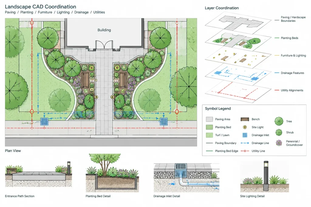
A landscape plan in architectural CAD should communicate more than the location of a few trees and paved areas. It must relate planting, hardscape, site furnishings, building access, utilities, grading, and other site information without becoming difficult to read. Even when a landscape architect produces the final design, architectural teams often need a coordinated landscape background for site plans, presentation drawings, permit sets, and consultant exchanges.
The most reliable workflow begins with verified source files, a clear layer structure, and a deliberate graphic hierarchy. Plant symbols and decorative hatches should come later. This guide explains how to build a landscape plan that remains legible, coordinated, and practical to revise.
Start with the correct site information
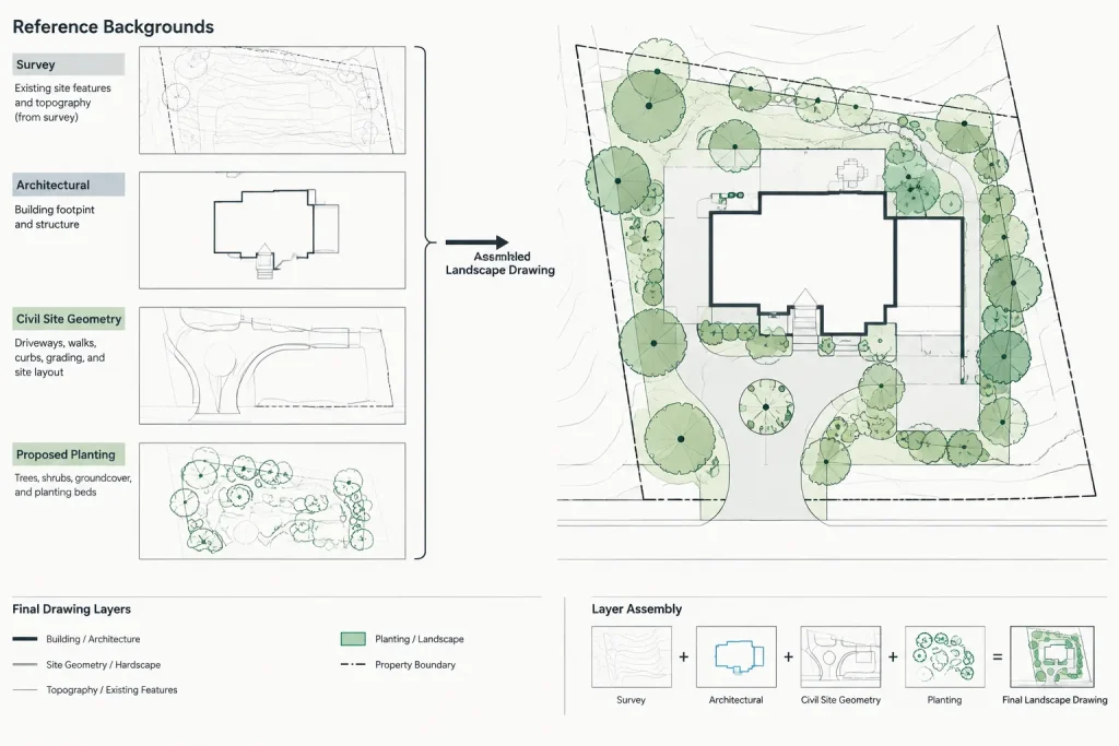
Do not begin by drawing planting symbols over an unverified building footprint. Assemble the current project backgrounds first and determine which discipline controls each type of information.
- Survey base: Property information, existing features, spot information, and other surveyed conditions should come from the project survey rather than an architectural approximation.
- Architectural background: Use the current building footprint, entrances, exterior doors, overhangs, canopies, steps, ramps, and related elements.
- Civil or grading background: Coordinate curbs, drainage features, grading, utility alignments, and paved areas with the responsible consultant.
- Landscape design information: Confirm proposed planting areas, plant identifiers, hardscape limits, edging, irrigation-related coordination zones, and site furnishings.
Before drafting, verify drawing units, project coordinates, orientation, and the relationship between referenced files. A background that appears visually aligned can still be incorrect if it has been moved, rotated, or scaled independently.
Define the purpose and drawing scope
A landscape concept plan, planting plan, hardscape plan, and architectural site plan do not need to show identical information. Decide what the drawing is intended to communicate before choosing symbols or adding notes.
An architectural site plan may show broad planting zones and representative trees for context. A planting plan may need individual plant locations, identifiers, quantities, and a coordinated schedule. A hardscape plan may emphasize paving boundaries, joints, transitions, walls, steps, and site furnishings while reducing planting graphics to a lighter background.
Separating these purposes prevents one drawing from carrying every available site element. It also makes plotting and revision control more manageable.
Organize landscape CAD layers by function
Landscape information should not be placed on one general layer. Separate layers allow the drafter to control visibility, color, linetype, and plotted emphasis for different drawing types.
| Information group | Typical content | Coordination purpose |
|---|---|---|
| Existing landscape | Existing trees, planting beds, and features designated to remain or be removed | Distinguishes surveyed conditions from proposed work |
| Proposed trees | Tree trunks, canopies, and plant identifiers | Supports spacing review and schedule coordination |
| Shrubs and groundcover | Shrub symbols, mass planting outlines, and groundcover zones | Keeps dense planting graphics controllable |
| Hardscape | Walks, plazas, paving fields, edging, and material boundaries | Coordinates circulation and surface transitions |
| Site furnishings | Benches, tables, planters, bicycle parking, receptacles, and similar items | Allows independent visibility and equipment coordination |
| Annotation | Plant tags, leaders, notes, and area labels | Separates information from physical geometry |
| Reference backgrounds | Architecture, survey, civil, utilities, and lighting | Preserves source ownership and display control |
Layer names should follow the project CAD standard. The exact naming format matters less than consistent separation and predictable use throughout the drawing set.
Create plant symbols that remain readable
Separate trunk and canopy graphics
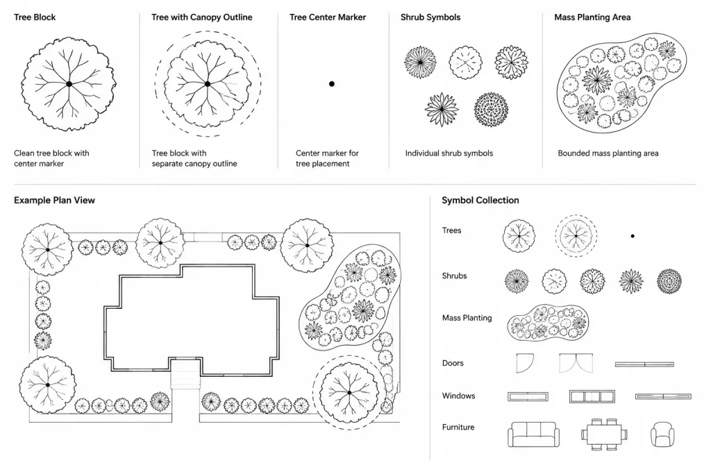
A tree symbol often needs to communicate both its placement point and the approximate visual spread assigned by the designer. Keeping the trunk or center marker distinct from the canopy makes the insertion point clear and helps users understand which geometry controls the location.
Avoid symbols with excessive internal linework. Dense branch patterns may look attractive on screen but can merge into a dark patch when plotted at a smaller scale. Test symbols at the intended sheet scale before using them throughout the plan.
Use consistent insertion points
The insertion point for a tree block should normally correspond to the intended tree center. Shrub and furnishing blocks also need logical insertion points so that replacements and schedule updates do not shift their positions unexpectedly.
If a symbol contains an identifier, keep the text readable when the block is rotated. Do not mirror text merely to alter the visual variation of a plant symbol. Where natural variation is desired, create controlled symbol alternatives rather than making the underlying information unpredictable.
Distinguish individual and mass planting
Drawing every plant as an individual detailed symbol can overwhelm a large planting bed. Use individual symbols where exact placement is important and use bounded planting areas where the design is communicated as a continuous mass. The selected method should match the documentation scope and the way quantities are calculated.
Draft hardscape as coordinated geometry
Hardscape should be based on clean boundaries rather than disconnected hatch patterns. Draw the limits of walks, plazas, patios, planting beds, and paving changes as coordinated geometry first. Apply hatches only after the boundaries are stable.
Where paving meets a building, curb, step, ramp, drain, or landscape edge, compare the plan with relevant grading and architectural information. A visually neat paving pattern does not resolve an elevation conflict or drainage issue.
Keep material boundaries separate from decorative hatch lines. This makes it easier to revise the shape of a paved area, calculate areas when required, and simplify graphics for other sheets. If joint patterns are shown, treat them as purposeful design information and coordinate their origin with entrances, edges, and prominent site elements.
Coordinate circulation and site furnishings
Landscape plans influence how people approach and move around a building. Review proposed planting and furniture against entrance routes, gates, stairs, ramps, parking connections, service paths, and emergency access information provided by the project team.
Site furnishing blocks should represent the relevant footprint and orientation without implying unverified product details. A generic bench or planter symbol is useful during planning, but it should not be mistaken for a confirmed manufacturer model. Once products are selected, coordinate the block, schedule, specifications, and installation information.
Also review trees and large planting zones against lighting, signs, utilities, overhead elements, drainage structures, and building maintenance access. These relationships may require input from several consultants rather than a drafting-only solution.
Manage planting tags and schedules
Plant tags should connect plan symbols to a planting schedule or other project data source. Establish a consistent identifier format and determine whether a tag refers to an individual plant, a group, or a bounded planting area.
- Place tags where leaders can be followed without crossing unrelated symbols.
- Keep annotation separate from plant geometry so it can be repositioned for different sheets.
- Avoid manually copying quantities into several unconnected notes.
- Check that every scheduled identifier appears in the plan and that every plan identifier has a corresponding entry.
- Flag uncertain species, sizes, quantities, or product selections for verification rather than guessing.
If quantities are generated or checked from CAD geometry, confirm how grouped blocks, arrays, repeated references, and mass planting areas are counted. A visually repeated object is not always equivalent to a verified schedule quantity.
Control graphic hierarchy
The primary design information should read first. Proposed trees, planting limits, paving edges, and key labels generally need more emphasis than consultant backgrounds. Existing information, utilities, and secondary context can often be displayed more lightly, provided they remain understandable.
Use hatches and canopy graphics carefully where they overlap. Transparent-looking effects may behave differently across plotting workflows, so produce test plots rather than relying only on the model-space display. Simplify the background where appropriate, but do not hide information needed to identify a coordination conflict.
Run a landscape plan coordination check
Before issuing the drawing, review it at both model level and plotted sheet scale. A useful check includes the following:
- Confirm that references use the agreed origin, orientation, units, and current file revision.
- Compare the building footprint and entrances with the latest architectural plan.
- Review hardscape limits against grading, drainage, and civil information.
- Check planting against utilities, lighting, signs, walls, overhangs, and access routes.
- Verify that plant and furnishing blocks use logical insertion points and approved layer assignments.
- Compare plant tags with the current schedule and resolve missing or duplicate identifiers.
- Look for open hatch boundaries, overlapping outlines, stray objects, and hidden duplicate blocks.
- Plot the sheet to confirm lineweight, text size, hatch density, and symbol readability.
Keep design responsibility visible
A coordinated CAD drawing does not replace professional verification. Landscape placement may be affected by local regulations, environmental conditions, visibility needs, utility restrictions, maintenance requirements, product data, and discipline-specific design decisions. Do not infer these requirements from a generic CAD block or a downloaded example.
The architectural CAD team adds value by maintaining reliable backgrounds, clear geometry, controlled layers, and visible coordination issues. With that foundation, landscape information can move between concept drawings, consultant files, and construction documents without becoming detached from the rest of the project.
Plan the CAD handoff before drafting
A landscape drawing is easier to coordinate when the project team agrees on how information will be exchanged. Confirm which files are reference backgrounds, which file contains editable landscape work, and which discipline is responsible for revising each category of geometry. This prevents architectural adjustments from being mistaken for survey, civil, or landscape design changes.
Keep received consultant files identifiable and avoid silently altering them to make the drawing appear coordinated. If a background requires repositioning, cleanup, or interpretation, document the issue and confirm the intended correction with the responsible team member.
Separate source geometry from presentation graphics
Geometry used for coordination should remain distinguishable from graphics added only for visual effect. Paving outlines, planting limits, tree centers, furnishing footprints, and access edges may affect other disciplines. Shadows, poche, decorative textures, and presentation canopies generally serve a different purpose.
This separation makes it easier to simplify a sheet without removing the underlying information needed for design review. It also reduces the risk that a decorative hatch or symbol outline will be treated as a verified construction boundary.
Track unresolved conditions visibly
Do not resolve an uncertain condition by making the linework look finished. Use the project review process to identify conflicts involving entrances, paving transitions, drainage features, utilities, lighting, furnishings, planting, and maintenance access. Unresolved items should remain visible to the people responsible for deciding them.
When revised backgrounds arrive, compare them with the previous issue before replacing references or accepting changed geometry. Pay particular attention to building edges, exterior doors, curbs, walks, walls, utility features, and other elements that directly influence landscape placement.
Prepare a clean deliverable
Before transferring or archiving the CAD file, remove unintended temporary objects while retaining information required to understand the drawing. Confirm that references can be identified, layers have meaningful purposes, blocks use dependable insertion points, and annotation remains editable.
- For consultant exchange: Preserve coordinate relationships and make the source and status of each background clear.
- For drawing production: Confirm that viewport visibility, plotting behavior, and annotation support the intended sheet purpose.
- For future revisions: Keep physical geometry separate from tags, schedules, hatches, and presentation effects.
- For review: Provide enough context to evaluate conflicts without allowing background information to overpower the landscape scope.
A well-prepared landscape CAD plan supports both visual communication and technical coordination. Its value comes from traceable information, editable geometry, disciplined file organization, and clear limits on what has or has not been verified.
Landscape Plan CAD Questions
Should the architectural building plan be copied into the landscape drawing?
A controlled reference background is generally more dependable than manually redrawing or copying the building footprint. The project workflow should preserve the architectural team’s ownership of building geometry while allowing the landscape file to display the current approved background.
How much detail should a tree or shrub CAD block contain?
Use enough detail to distinguish the plant type or graphic category at the intended plotted scale. Avoid intricate linework that obscures nearby tags, utilities, paving edges, or other planting. The insertion point and layer behavior are usually more important for coordination than decorative complexity.
Should planting and hardscape appear on the same plan?
That depends on the drawing purpose and information density. They can share a plan when both remain legible, but separate planting and hardscape views may provide better control when boundaries, tags, joints, furnishings, and backgrounds compete for space.
How should architectural drafters handle uncertain plant information?
Do not invent species, sizes, quantities, or identifiers. Keep the uncertain item clearly marked for review and obtain direction from the responsible designer or consultant before treating it as confirmed project information.
Why can a landscape plan look aligned but still be incorrectly coordinated?
Files can appear aligned after an unrecorded move, rotation, or scale adjustment. Reliable coordination requires confirmation of the project origin, orientation, units, and reference relationship rather than visual alignment alone.
What should be checked after a consultant background is updated?
Compare the revised file with the prior background and review changes near building entrances, paving limits, curbs, walls, drainage elements, utilities, lighting, access routes, furnishings, and planting areas. Then recheck tags, hatches, and annotation affected by the changed geometry.