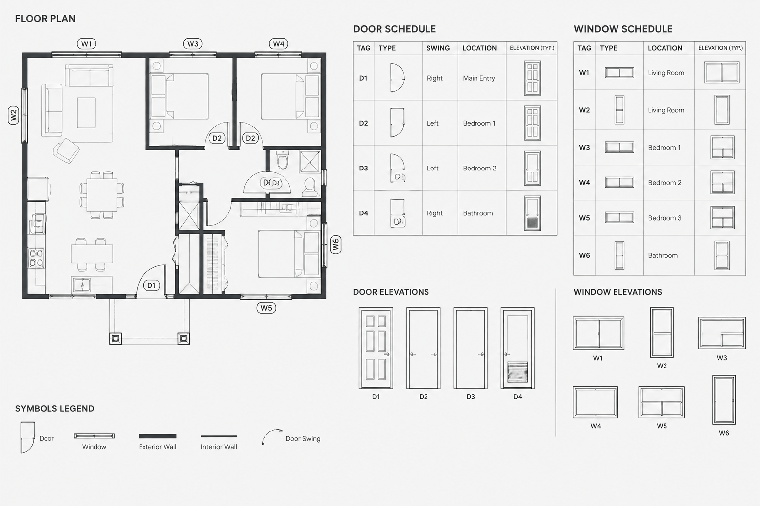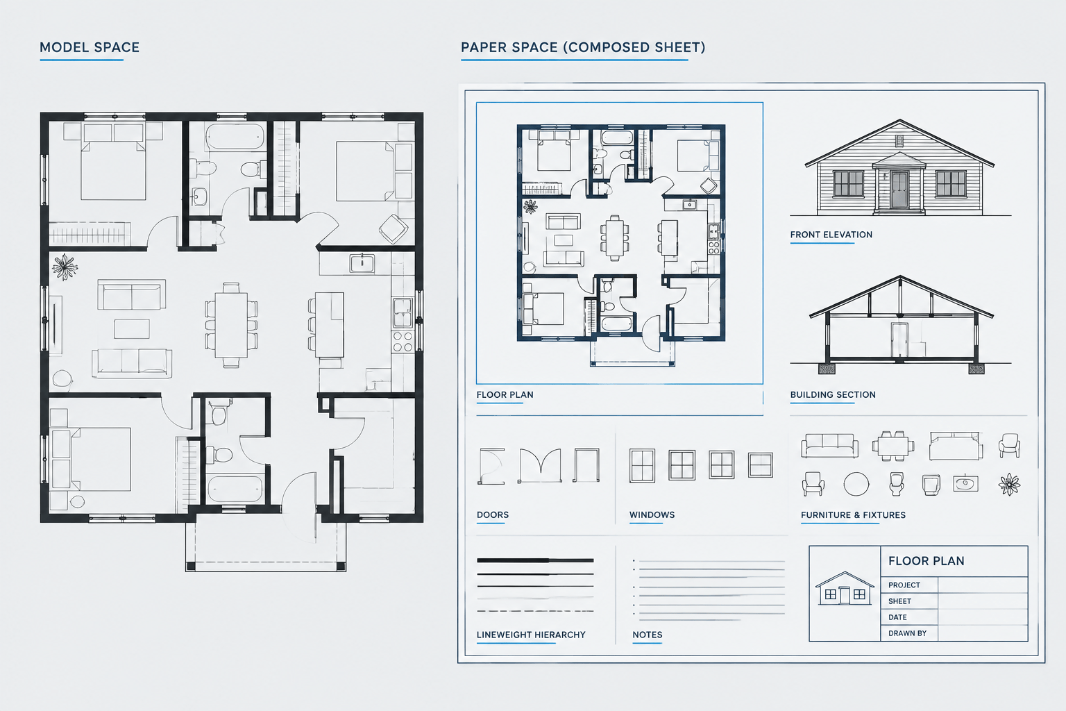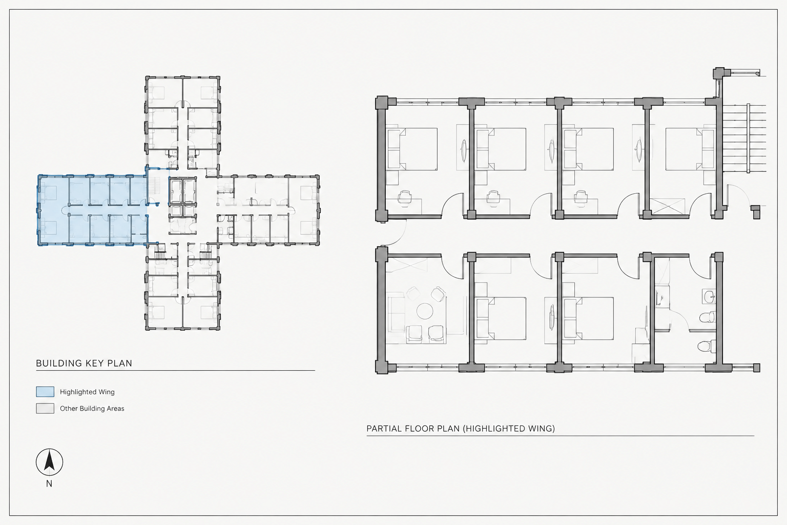
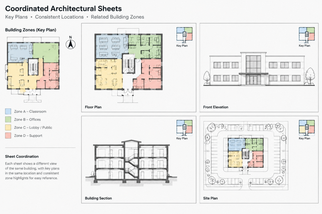
An architectural key plan is a small, simplified building or site diagram that shows where the content of a drawing sheet is located within the larger project. It helps readers understand partial plans, enlarged areas, building wings, renovation zones, and phased work without repeatedly searching through the full drawing set.
Although a key plan occupies relatively little space on a sheet, it requires careful coordination. An outdated outline, inconsistent orientation, or unclear highlight can send a contractor or reviewer to the wrong part of the building. The most reliable approach is to derive key plans from controlled project geometry and treat them as coordinated drawing elements rather than decorative sheet graphics.
What an Architectural Key Plan Should Communicate
A useful key plan answers three questions quickly:
- What building, floor, wing, or site area is being shown?
- Which portion of that larger area is covered by the current drawing?
- How is the diagram oriented relative to the main plan and the rest of the drawing set?
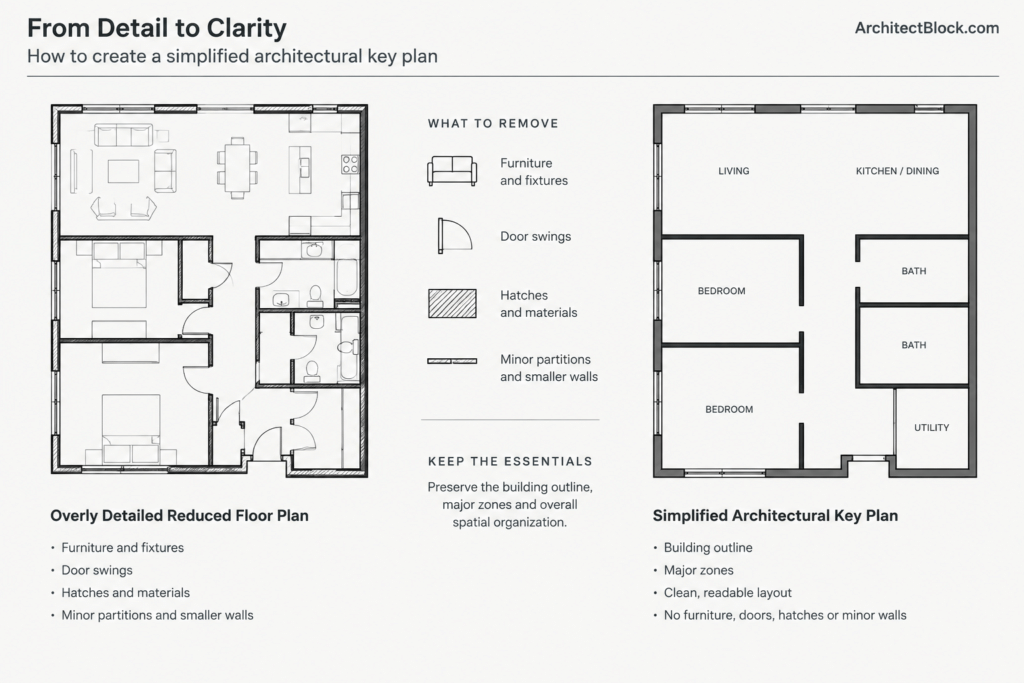
The key plan does not need to reproduce every wall, door, fixture, or annotation. Its purpose is location, not detailed design communication. Too much information makes the diagram difficult to read at its small plotted size.
Depending on the project, a key plan may show a building footprint, major wings, floor divisions, expansion joints, site boundaries, principal circulation zones, or another stable organizing feature. The selected geometry should help a reader recognize the project structure immediately.
Choose the Right Source Geometry
Begin with an authoritative project base rather than tracing a key plan independently on every sheet. The source might be a coordinated overall floor plan, a simplified building-outline file, or a dedicated diagram maintained for sheet graphics.
The source geometry should be current but visually restrained. Keep only the elements needed to understand location. Typical candidates include:
- Exterior building outlines
- Major internal separations between wings or zones
- Primary corridors or circulation spines when they clarify orientation
- Floor or building identifiers
- North indication when relevant to the drawing set
- Property or site outlines for site-related sheets
Avoid relying on furniture, finish patterns, door swings, room tags, dense hatches, or detailed construction lines. These may be important in the main plan but usually become visual noise in a reduced key plan.
Live Reference or Controlled Snapshot?
A live external reference can keep the key plan aligned with the current design, but it may also bring unnecessary layers and frequent graphic changes into many sheets. A controlled snapshot or dedicated simplified file offers more graphic stability, but someone must update it when the building outline changes.
The appropriate method depends on the project workflow. Whichever method is selected, document who maintains the key plan source and when it should be checked. Avoid mixing unrelated methods across sheets because that makes discrepancies harder to detect.
Build a Clear Graphic Hierarchy
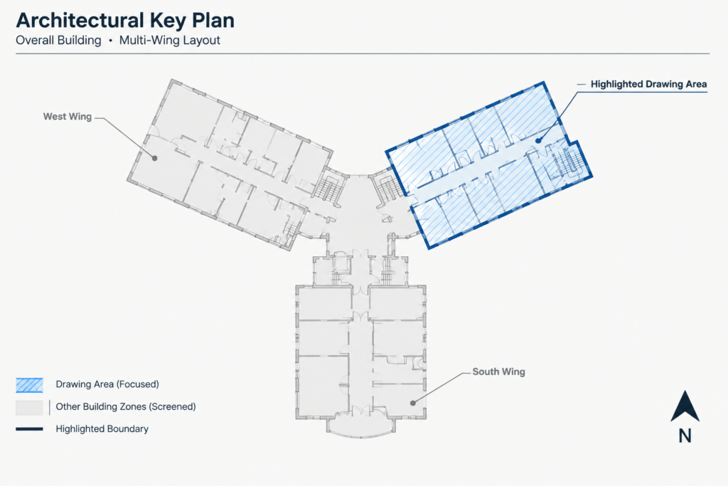
The highlighted area should be the most noticeable part of the diagram, while the surrounding context remains visible but secondary. This can be achieved through lineweight, screening, solid or patterned fills, boundary emphasis, or a combination of these methods.
| Key plan element | Graphic role | Drafting approach |
|---|---|---|
| Overall building or site | Provides context | Use simplified, visually subdued outlines |
| Area shown on the sheet | Primary emphasis | Apply a distinct fill, heavier boundary, or clear contrast |
| Adjacent zones | Supports orientation | Keep visible without competing with the highlighted area |
| Zone labels | Identifies divisions | Use short, consistent names placed in open areas |
| Orientation symbol | Relates the diagram to the project | Use only when it adds useful directional information |
Always review the graphic at its intended plotted size. A highlight that looks obvious while zoomed in may disappear when printed. Conversely, a dense fill may obscure the building outline or become a dark patch on a reduced sheet.
Coordinate Orientation Across the Drawing Set
Key-plan orientation should be deliberate and consistent. In many sets, the diagram matches the orientation of the overall plan. In others, it matches a standard project orientation even when a partial plan has been rotated to fit the sheet.
Either approach can work if readers can understand the relationship. Problems arise when key plans rotate unpredictably from one sheet to another or when a north symbol is copied without being checked. Establish a project rule early and apply it consistently.
If a partial plan is rotated relative to the overall plan, consider whether the key plan needs an additional directional cue. Do not assume that the sheet edge indicates north unless that convention has been explicitly established and maintained.
Create Logical Plan Zones
Large buildings are often divided into wings, sectors, quadrants, or other drawing areas. Those divisions should follow recognizable project features whenever possible. Major walls, circulation paths, structural separations, or clear building forms are generally easier to interpret than arbitrary boundaries.
Zone names should remain stable throughout the drawing set. A wing identified one way on the floor-plan sheet should not receive a different abbreviation on a ceiling, finish, or enlarged-plan sheet. Maintain a shared list of zone identifiers and use the same spelling, capitalization, and sequence everywhere.
When adjacent plans overlap, show the relationship carefully. The key plan can highlight the primary coverage of the current sheet, while match lines and references in the main plan explain the detailed overlap. Do not use the key plan as a substitute for proper match-line annotation.
Set Up Layers and Reusable Components
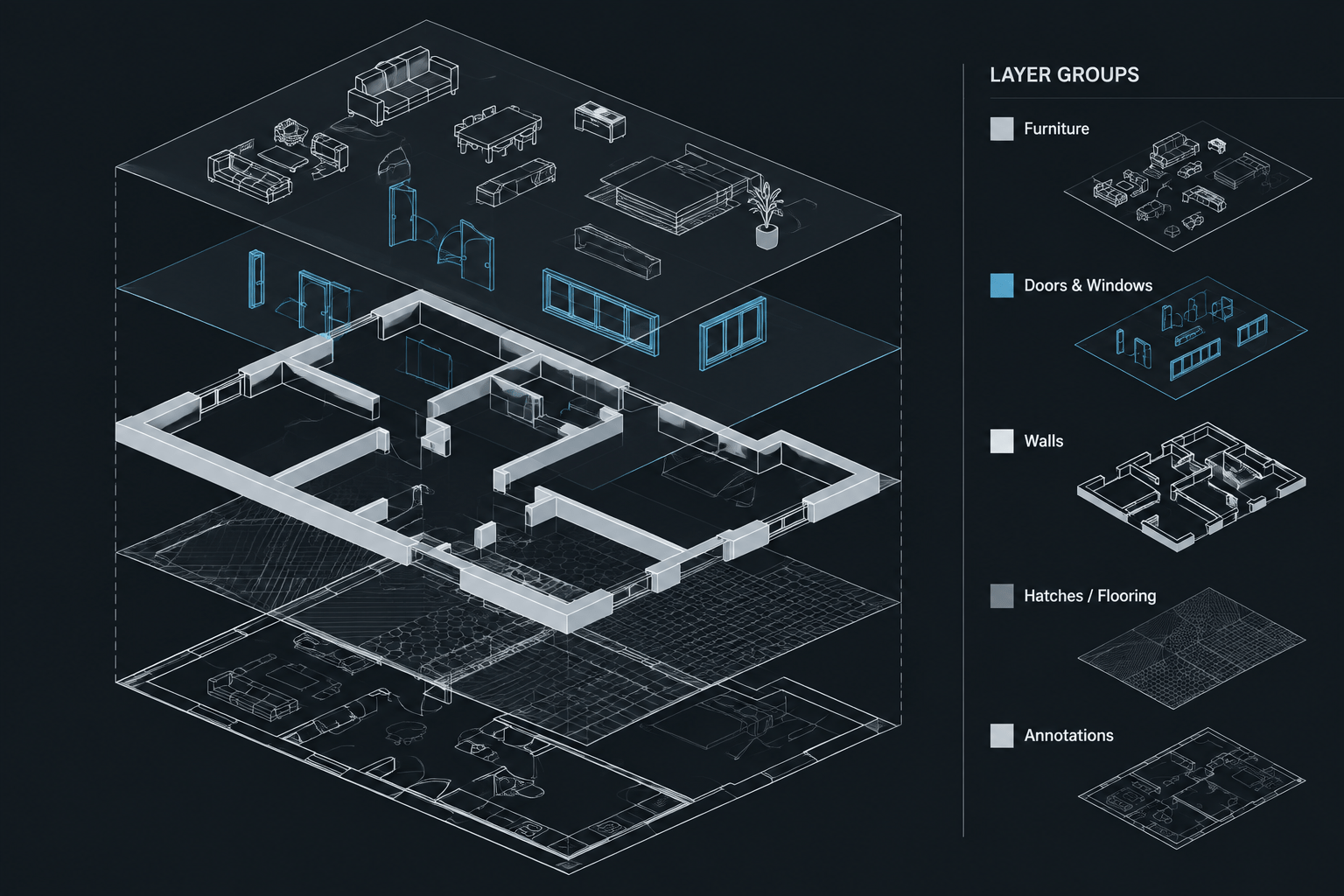
Separating key-plan elements by function makes editing and plotting easier. A practical layer structure may distinguish the contextual outline, highlighted region, labels, boundaries, and orientation graphics. Layer names should follow the project CAD standard rather than introducing a separate naming system for one diagram.
Reusable components can improve consistency. Zone labels, north indicators, and key-plan titles may be created as controlled blocks when repeated across many sheets. If attributes or fields are part of the office workflow, they can help manage variable text, but the resulting display must still be reviewed sheet by sheet.
A reusable block should not contain project-specific geometry that is likely to change. Keep stable graphic components reusable while allowing the building outline and highlighted region to remain coordinated with the project base.
Place the Key Plan on the Sheet
Locate the key plan where readers can find it consistently. Common locations include the title-block area, a sheet-information column, or an open portion of the drawing field. The best location depends on the sheet template and the amount of available space.
Keep the key plan large enough to remain legible but subordinate to the main drawing. It should not compete with the floor plan, section, or detail that forms the sheet’s primary content. If the building shape is too complex to read at the available size, simplify the geometry rather than shrinking it further.
Use the same placement and approximate graphic scale across related sheets when practical. A key plan that jumps between corners or changes size without reason makes sheet comparison less efficient.
Coordinate Key Plans with Sheet Content
The highlighted area must match the actual extent shown in the primary viewport or drawing. Check this relationship whenever a crop boundary, match line, plan rotation, or sheet assignment changes.
For sheets containing several enlarged areas, decide whether one key plan can communicate all locations clearly. Separate highlights, numbered markers, or multiple small diagrams may be appropriate, but only if their relationship to the views is unambiguous. Avoid piling many colors or hatch patterns into one tiny diagram.
Key plans should also agree with view titles, match-line references, drawing titles, and the sheet index. If the key plan identifies a wing or floor that is not reflected in the sheet title, the discrepancy should be resolved rather than left for the reader to interpret.
Quality-Control Checklist
Before issuing a drawing set, review key plans as part of sheet coordination rather than as an isolated graphic task.
- Confirm that the outline matches the current building or site configuration.
- Verify that the highlighted region matches the content shown on the sheet.
- Check zone names against the overall plans and sheet titles.
- Confirm that orientation is consistent and any directional symbol is correct.
- Review lineweights, fills, and labels at plotted size.
- Remove unnecessary detail that reduces legibility.
- Check that referenced files, layers, and blocks display correctly.
- Compare related sheets to find inconsistent placement or highlighting.
- Ensure that renovation phases or separate work areas are not accidentally combined.
Common Key-Plan Problems to Avoid
Independent Copies on Every Sheet
Duplicating loose geometry creates multiple versions that can drift apart. Use a controlled source and limit sheet-specific work to the highlighted area or necessary labels.
Excessive Plan Detail
A reduced floor plan is not automatically an effective key plan. Simplify aggressively so the building form and selected area remain clear.
Unclear Highlighting
Do not rely on subtle color differences that may disappear in grayscale output. Test contrast using the actual plot configuration intended for the set.
Uncoordinated Rotation
A rotated partial plan may require additional explanation. Verify that the relationship between the key plan and the main drawing is understandable without guesswork.
Stale Building Outlines
Key plans are easy to overlook after design changes. Include them in drawing-update and issue-review procedures, especially when additions, boundaries, or plan zones change.
A Small Diagram with a Large Coordination Role
A well-made architectural key plan gives readers immediate context while taking up minimal sheet space. Its effectiveness depends on controlled source geometry, restrained graphics, stable zone names, consistent orientation, and regular coordination with the views it represents.
Treat the key plan as part of the drawing-navigation system alongside sheet titles, match lines, callouts, and drawing references. When those elements agree, even a large architectural set becomes easier to read and less prone to location-related confusion.