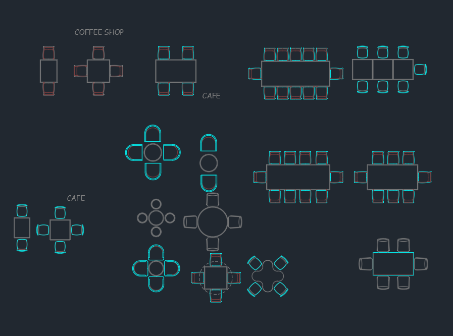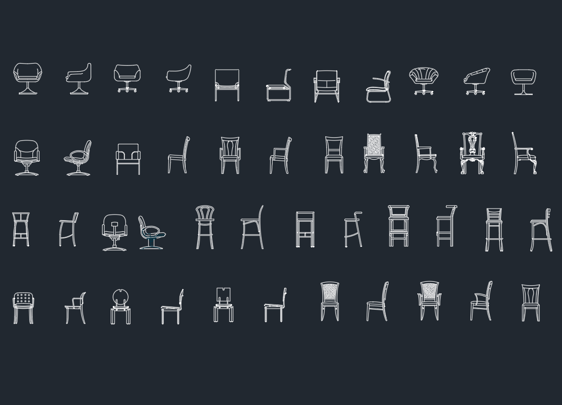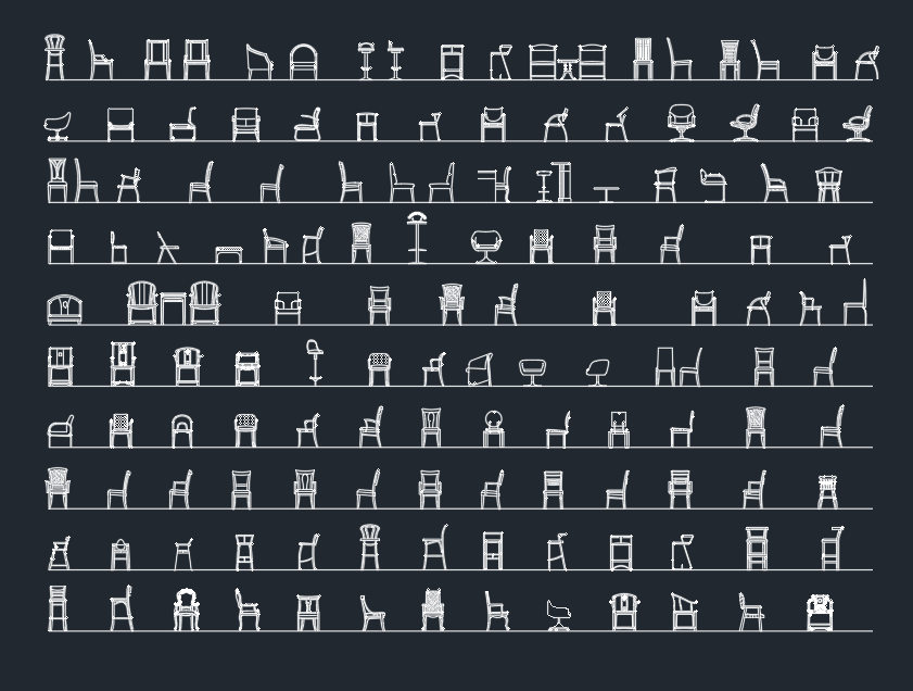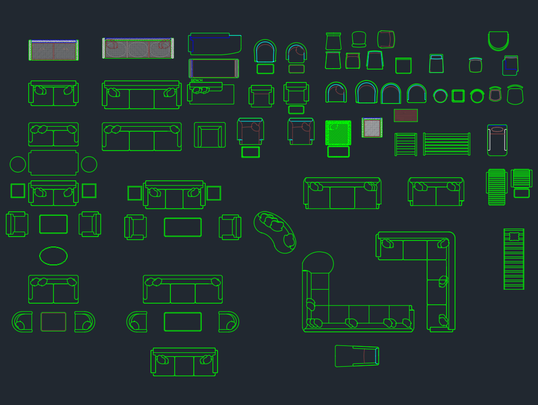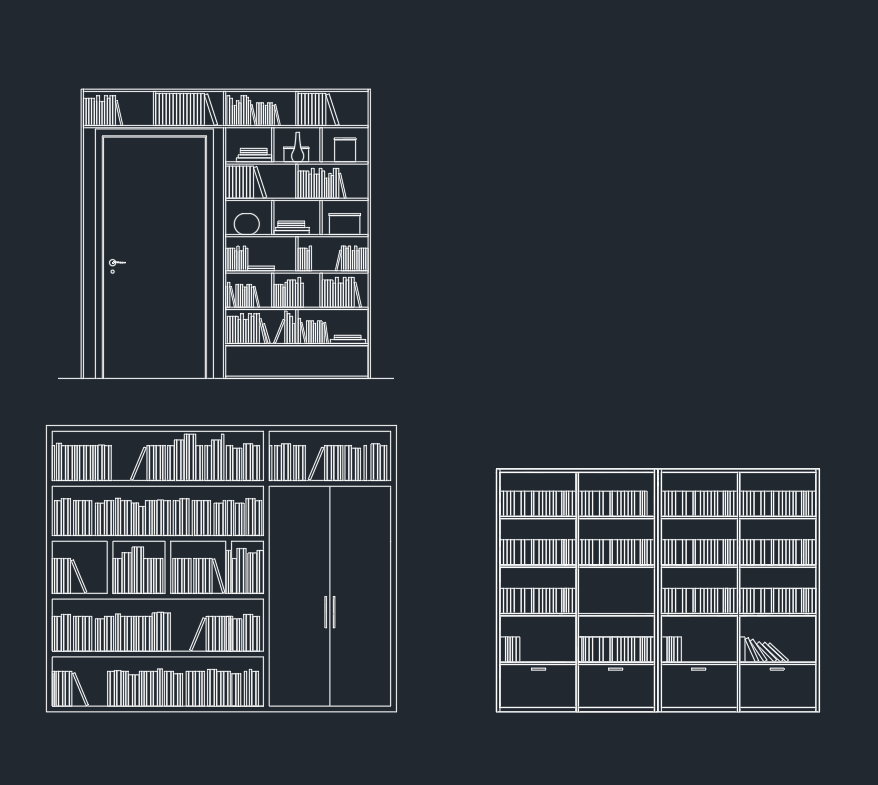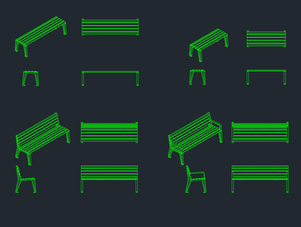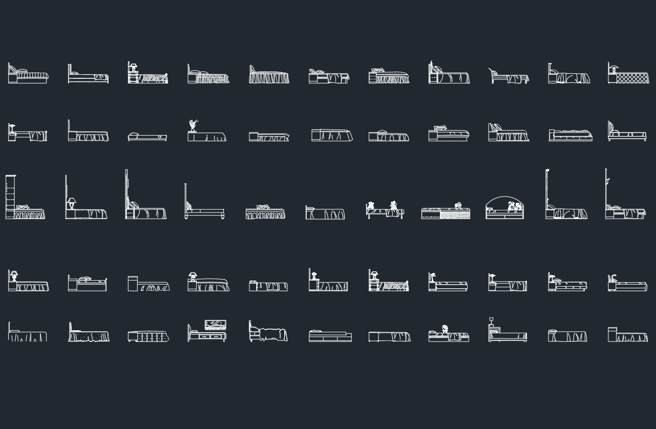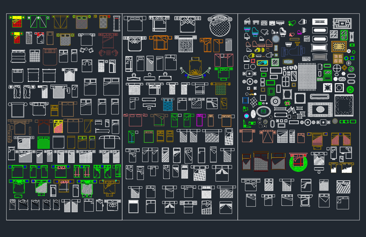
A CAD block may look correct but still be frustrating to use if its insertion point is poorly located. The insertion point controls how the block attaches to the cursor, aligns with nearby construction, rotates, and responds when replaced or redefined. A thoughtful base point can make repeated placement quick and predictable; a careless one can force users to move every inserted object manually.
There is no single correct insertion point for every architectural block. The best location depends on what the object represents, how it is normally positioned, and which part of its geometry must coordinate with the building. This guide explains how to choose useful CAD block insertion points for plans, elevations, sections, and detail components.
What Is a CAD Block Insertion Point?
The insertion point is the reference location used to place a block in a drawing. When the block is attached to the cursor, this point becomes the placement handle. Its coordinates also act as the local origin for the block definition.
The insertion point affects several common operations:
- Placing a block against a wall, grid, countertop, or other reference
- Rotating an object around a meaningful location
- Replacing one block definition with another
- Reading or editing a block reference through properties
- Aligning repeated objects consistently
- Creating arrays or patterned layouts
- Using blocks in office libraries and tool palettes
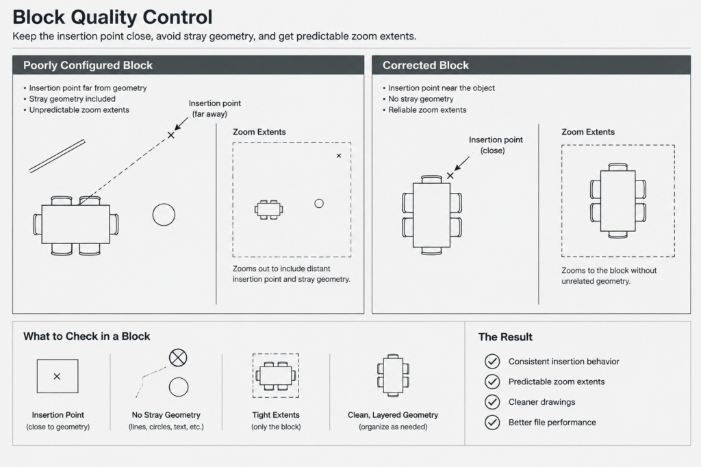
A block can technically use a point far away from its visible geometry, but that arrangement is rarely practical. It may cause unexpected zoom extents, awkward cursor movement, and inaccurate placement.
Start with the Object’s Coordination Point
The most useful insertion point is usually the location where the object connects to, rests against, or aligns with another architectural element. This is more reliable than automatically choosing the geometric center.
Before defining a block, ask:
- What will the drafter snap this object to?
- Which edge or centerline controls its position?
- Where should the object rotate from?
- Does the placement point remain meaningful if the block changes size?
- Will the same definition be used in more than one drawing orientation?
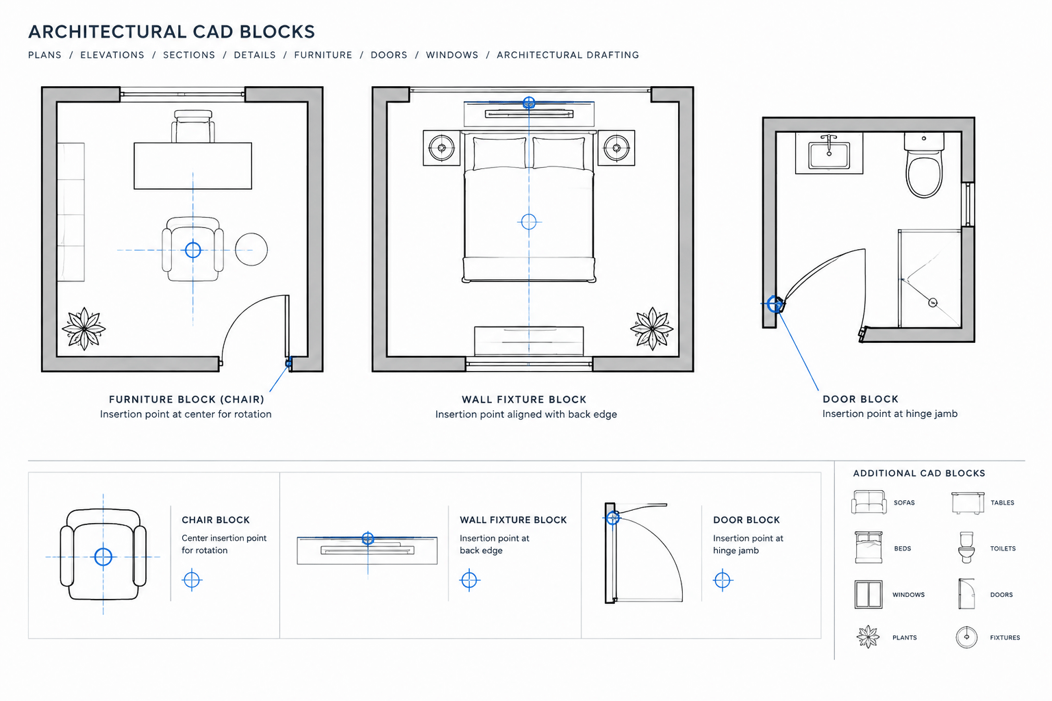
For example, a freestanding table may be positioned from its center, while a wall-mounted fixture is more naturally placed from its wall connection. The object’s use should determine the base point.
Recommended Insertion-Point Strategies by Block Type
| Block type | Practical insertion-point location | Why it works |
|---|---|---|
| Freestanding furniture | Geometric or functional center | Supports room-layout studies, rotation, and balanced alignment. |
| Furniture placed against a wall | Center or corner of the wall-facing edge | Makes it easier to snap the object directly to a wall or clearance line. |
| Plumbing fixture | Fixture centerline at the wall-facing connection | Coordinates the fixture with partitions and service locations. |
| Door symbol | Hinge-side jamb or another documented opening reference | Provides a stable point for locating and rotating the door within an opening. |
| Window symbol | Opening centerline or a consistent jamb reference | Supports alignment with wall openings and dimension strings. |
| Column or structural grid object | Center of the controlling grid intersection | Maintains direct coordination with the structural layout. |
| Casework module | Back corner or center of the wall-facing edge | Supports sequential placement along walls and countertops. |
| Elevation entourage | Center or corner along the baseline | Keeps people, furniture, and planting graphics aligned with the floor or grade line. |
| Detail component | Primary intersection, face, or connection point | Allows the component to snap to controlling detail geometry. |
| Annotation symbol | Symbol center or leader attachment point | Makes placement and alignment visually predictable. |
These are workflow recommendations rather than universal rules. Office standards, block behavior, and project conditions may require a different reference point.
Plan Blocks Versus Elevation Blocks
Insertion points for plan-view blocks
Plan blocks typically coordinate with walls, room boundaries, grids, and circulation paths. A useful plan insertion point should support horizontal placement and rotation. For objects that can face several directions, select a point that remains logical as the block rotates.
A chair placed from its center is easy to rotate around a table. A toilet, sink, or wall cabinet is usually easier to position from the center of its wall-facing edge. A door should rotate around a point related to its hinge or opening rather than the center of the leaf.
Insertion points for elevations and sections
Elevation blocks often depend on a baseline. People, beds, cabinets, appliances, and landscape elements generally need to sit on a floor, countertop, shelf, or grade reference. Placing the insertion point on that baseline prevents the block from appearing to float above or sink below the supporting surface.
For wall-mounted elevation objects, use the point that controls both horizontal location and mounting relationship. The block geometry itself should not be treated as verified installation information; actual mounting conditions and product requirements must be checked separately.
Center Points, Corners, and Connection Points
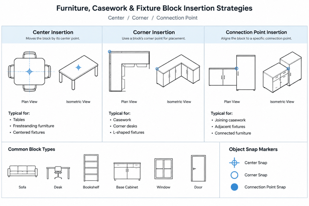
Use a center point when rotation is important
Center-based insertion works well for objects moved freely within a space. Tables, stools, decorative objects, and some planting symbols are common examples. Rotation feels natural because the object remains centered on the cursor.
However, the visible bounding-box center is not always the functional center. An irregular desk may need to align from the user position, work-surface centerline, or wall-facing edge instead.
Use a corner when objects form a sequence
Corner insertion points are useful for modular casework, shelving, lockers, panels, and other objects commonly placed end to end. A known corner makes it easier to continue a run using object snaps.
Choose the same corresponding corner for related blocks. If one cabinet uses its back-left corner and another uses its front-right corner without a clear reason, exchanging or aligning the blocks becomes unnecessarily difficult.
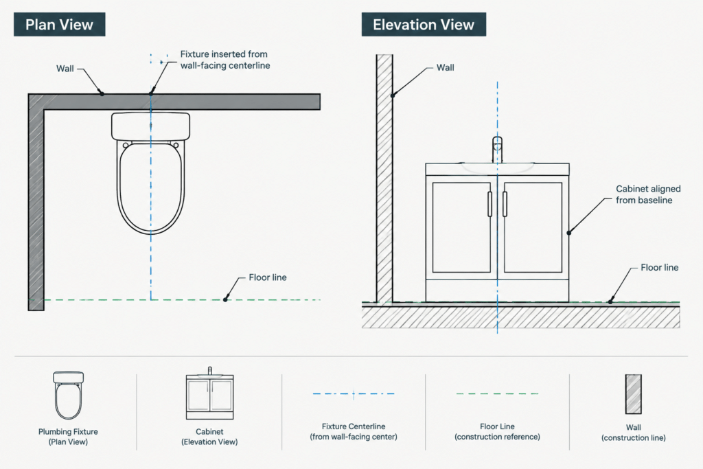
Use a connection point for building-mounted components
Objects connected to walls, ceilings, floors, or other systems benefit from insertion points at the connection. This category can include fixtures, equipment symbols, wall accessories, detail components, and some lighting graphics.
The connection point should represent drafting coordination, not an assumed physical connection that has not been verified. Manufacturer information and project documentation remain the authority for installation.
Orientation and Rotation Conventions
A good insertion point should be paired with a consistent default orientation. Related blocks should face the same direction when inserted at zero rotation. This reduces unnecessary rotation and makes a library easier to understand.
Establish an office convention for:
- The default facing direction of plan symbols
- The baseline used for elevation objects
- Which side is treated as the back or wall-facing side
- How left-hand and right-hand versions are represented
- Whether mirrored references are permitted or separate definitions are preferred
Mirroring may reverse text, attributes, asymmetrical hardware, or other meaningful graphics. Inspect mirrored results rather than assuming they are interchangeable.
How to Correct a Poor Insertion Point
Moving a placed block reference does not change the base point stored in its definition. To correct the insertion point, edit or recreate the definition so that its local origin is located at the intended coordination point.
A practical correction workflow is:
- Identify how the block is normally placed and aligned.
- Select a precise point on the geometry that supports that workflow.
- Edit the block definition or create a clean replacement definition using that point.
- Confirm that the visible geometry is close to the local origin.
- Test insertion, rotation, copying, mirroring, and replacement.
- Check existing references before redefining a block throughout a project.
Changing a definition can alter the apparent position of existing references because their stored insertion coordinates remain in place while the geometry shifts relative to the origin. Test the change in a controlled copy of the file before updating a project-wide block.
Avoid Hidden Geometry and Distant Extents
If a block jumps away from the cursor or creates unusually large drawing extents, inspect it for distant objects. Stray points, lines, attributes, wipeout boundaries, and nested content can make the block difficult to select or manage.
Review the entire definition, not just the visible symbol. Remove content that does not belong, but preserve intentional attributes, masking, and construction geometry required for the block’s operation. Also verify that nested blocks have sensible origins of their own.
Test the Block in a Real Drawing Context
A block should be tested where it will actually be used. Insert it into a temporary plan, elevation, or detail and evaluate the placement experience.
- Does the cursor attach at the expected location?
- Can the block snap directly to its controlling geometry?
- Does it rotate around a useful point?
- Is its default orientation predictable?
- Does it remain aligned when copied or arrayed?
- Are text and attributes readable after rotation or mirroring?
- Is the geometry drawn at the intended unit relationship and scale?
- Does the block remain manageable when placed on the project’s layers?
Also compare the block against verified project information. A convenient insertion point does not confirm that the object’s dimensions, clearances, specification, or accessibility conditions are suitable for construction.
Document Library Conventions
A shared CAD library becomes easier to maintain when insertion-point rules are documented. The rules do not need to be complicated. A short guide can state that freestanding furniture uses a center point, wall fixtures use a wall-facing centerline, elevation entourage uses a baseline, and modular casework uses a consistent back corner.
Include a simple preview or placement note when a block’s base point is not obvious. Consistent naming and orientation are especially important when several users create content for the same library.
Final Quality-Control Checklist
- The insertion point reflects how the object is normally coordinated.
- The block geometry is close to its local origin.
- The default orientation matches related library content.
- Rotation occurs around a useful point.
- No unintended geometry creates distant drawing extents.
- Nested blocks and attributes behave as expected.
- Plan and elevation versions use appropriate references for their views.
- Existing project references are reviewed before a definition is replaced.
- Dimensions and technical suitability are verified independently.
Well-chosen CAD block insertion points reduce placement corrections and make architectural drawing libraries more predictable. By treating the base point as a coordination tool rather than an arbitrary click, drafters can create blocks that are faster to place, easier to rotate, and safer to reuse across plans, elevations, and details.