Architectural CAD layer naming affects far more than the appearance of the layer list. It determines how quickly users can interpret a DWG file, isolate building elements, coordinate referenced drawings, manage renovation status, and troubleshoot plotting problems.
The framework below is intentionally platform-neutral and does not impose a proprietary standard. Use it to evaluate an office convention, organize a new project template, or plan the controlled cleanup of an existing drawing set. Contractual requirements, client standards, and established project procedures should take priority where they apply.
A good layer name should tell a CAD user what an object represents before that object is selected. It should also support predictable plotting, quick visibility control, consultant coordination, and future editing. When names are vague or inconsistent, even a visually correct drawing becomes difficult to maintain.
Architectural CAD layer naming does not require the longest possible code or an elaborate office manual. It requires a structure that matches the way the project team creates, views, exchanges, and plots information. This guide explains how to build that structure without prescribing a proprietary naming standard.
What a Layer Name Needs to Communicate
At minimum, a useful layer name identifies the drawing information assigned to it. Depending on the project, it may also describe the responsible discipline, graphic role, project phase, location, or status.
For example, a wall layer may need to distinguish architectural walls from structural elements. It may also need to separate existing construction from new work. A door layer might separate door geometry from door tags, swings, or overhead components.
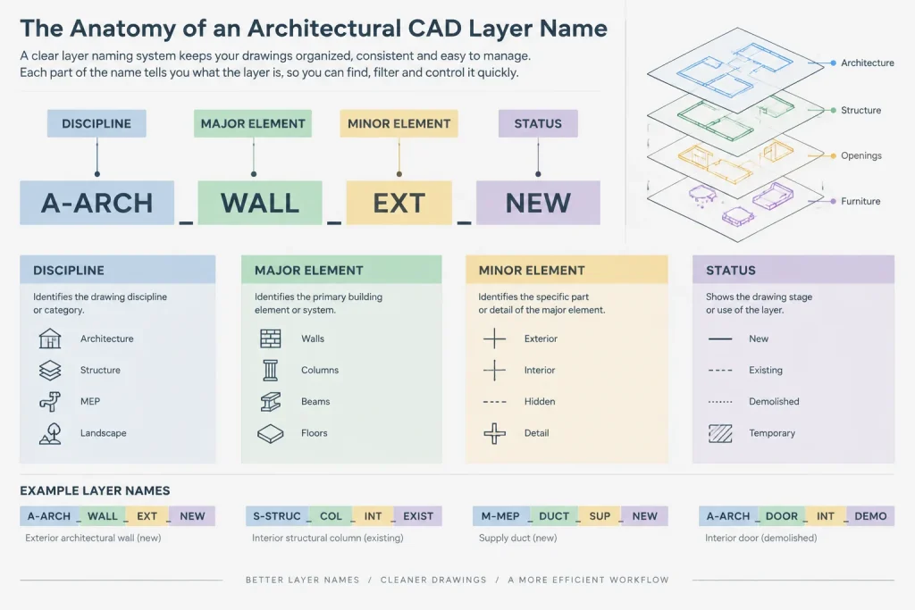
A practical layer name can be understood as a sequence of fields:
- Discipline: The team or drawing category responsible for the information.
- Major element: The principal building or site object, such as walls, doors, ceilings, furniture, or paving.
- Minor element: A more specific component, graphic role, or subtype.
- Status or phase: Existing, demolished, new, temporary, or another project-defined condition.
- Optional modifier: Annotation, overhead, hidden, identification, or another distinction needed for display control.
Not every layer needs every field. The purpose is to produce meaningful and repeatable names, not to fill every available position.
Start with Drawing Control, Not Abbreviations
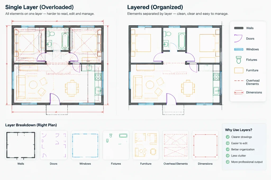
Before deciding how to abbreviate words, identify what users need to turn on, turn off, freeze, isolate, screen, or plot differently. Layer separation should follow real drawing-control needs.
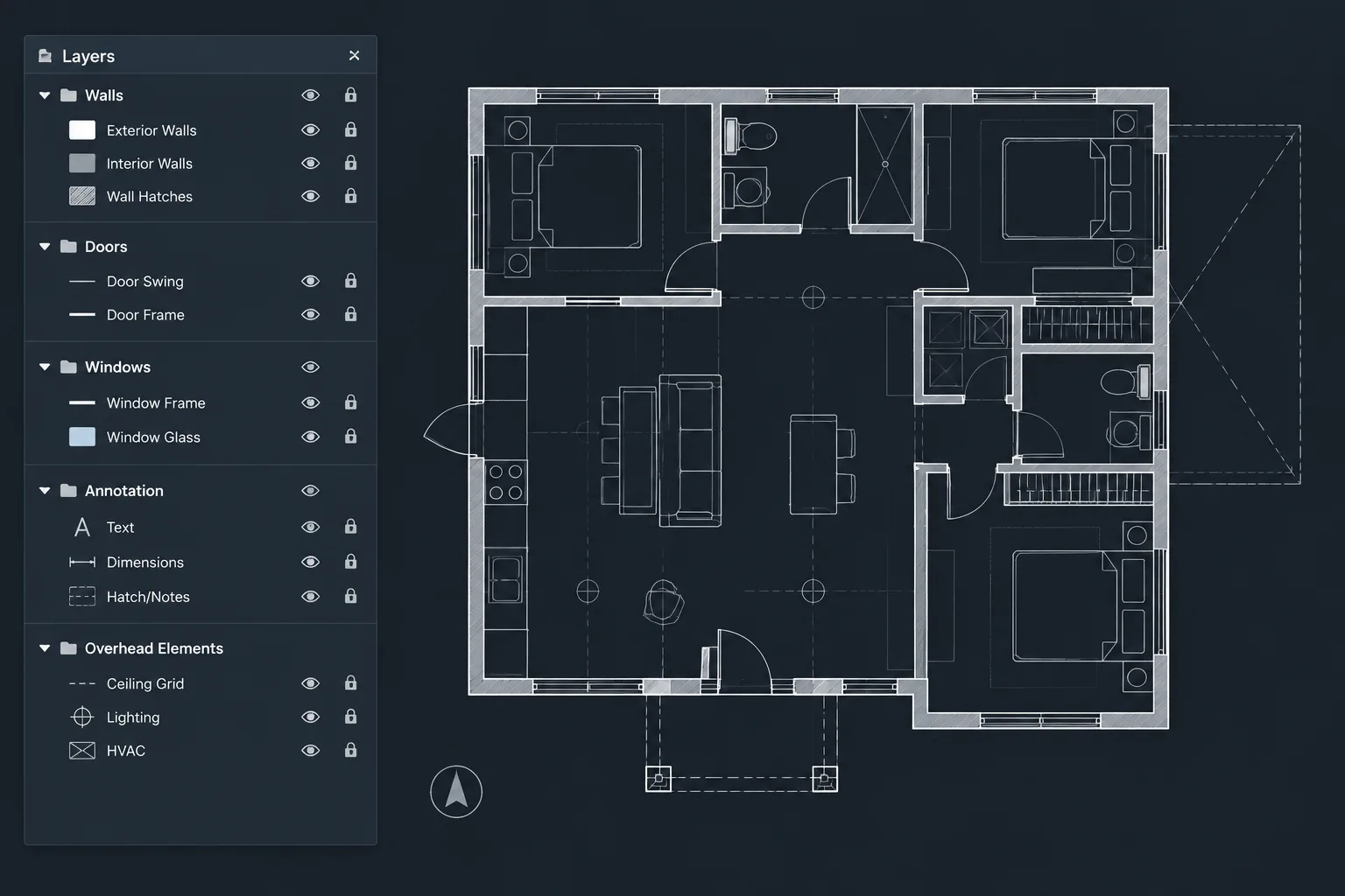
Consider a floor plan containing wall outlines, wall poche, door panels, door swings, room tags, dimensions, casework, plumbing fixtures, and overhead cabinets. Placing all of these objects on one floor-plan layer may seem simple, but it prevents selective visibility and graphic control. At the opposite extreme, assigning every object subtype to its own layer creates an unnecessarily large list.
A useful test is to ask three questions:
- Does this information need a different plotted appearance?
- Does it need to be hidden or shown independently in any view?
- Does another team member need to identify or manage it separately?
If the answer is yes, a separate layer may be justified. If the objects always share the same visibility, ownership, and graphic treatment, another layer may add complexity without improving control.
Choose a Consistent Naming Pattern
The exact abbreviations matter less than consistent field order. If one layer places the discipline first, another places it last, and a third omits it without a rule, alphabetical sorting becomes much less useful.
A straightforward office pattern might place information in this sequence:
| Field | Purpose | Conceptual examples |
|---|---|---|
| Discipline | Groups layers by responsible drawing category | Architectural, structural, civil, interiors |
| Major element | Identifies the primary object family | Walls, doors, windows, ceilings |
| Minor element | Distinguishes a component or use | Tags, swings, frames, overhead |
| Status | Separates project conditions when required | Existing, demolition, new |
Separators such as hyphens or underscores can make fields easier to scan. Select one separator system and use it consistently. Avoid depending on spaces, punctuation, or capitalization to carry important meaning unless the office workflow supports those conventions reliably.
Keep Abbreviations Decodable
Short names are convenient only when users can understand them. Create a controlled vocabulary for common elements and avoid inventing a new abbreviation each time a layer is added. For example, a project should not use several unrelated abbreviations for ceiling information simply because different people created the files.
Maintain a plain-language layer guide in the project documentation or CAD standards material. The guide should describe each approved abbreviation and explain when similar layers are used. This is especially helpful for new staff, outside collaborators, and archived projects.
Separate Model Information from Annotation
Geometry and annotation often require different visibility and plotting decisions. Walls may appear in several plan types, while room tags, dimensions, and notes may belong only to a specific presentation.
Common annotation categories include:
- Dimensions and dimension strings
- Text notes and leaders
- Room, door, window, and wall identification
- Section, elevation, detail, and enlarged-plan references
- Revision graphics
- View-specific symbols
Do not assume that every annotation type needs its own layer. Separate them when doing so supports sheet preparation, view management, plotting, or coordination. The objective is deliberate control rather than maximum subdivision.
Handle Existing, Demolition, and New Work Carefully
Renovation projects often require the same element to appear differently according to its status. The layer system must make that condition visible in both the layer name and the plotted result.
There are two common organizational approaches. One adds a status field to individual element layers. The other creates broader status groupings and then subdivides them by element. Either can work if it is applied consistently throughout the project.
Avoid relying only on color to indicate status. Colors can be changed by object overrides, viewport settings, plot configurations, or imported content. A meaningful layer name provides an additional check when a drafter inspects the object.
Also define how objects that remain in place are treated. Some teams classify retained construction as existing, while others distinguish verified existing work from background reference information. The project convention should make that distinction explicit.
Plan for Xrefs and Consultant Files
When an external reference is attached, its layer names appear with an identifying prefix associated with the referenced file. Long internal layer names can therefore become even longer in the host drawing. This is not a reason to use cryptic names, but it is a reason to avoid unnecessary wording.
Discipline identification inside a source file can still be valuable because drawings may be detached, exported, bound, archived, or reviewed independently. However, duplicating the same information in several fields may provide little benefit. Test the convention using a realistic host drawing with multiple referenced files before adopting it across a project.
Consultant layers should generally remain distinguishable from architectural layers. Renaming incoming layers without a defined exchange procedure can complicate updates and comparisons. If consultant content must be edited or converted, work from a controlled copy and document the changes.
Assign Properties Through Layers
A naming framework is most effective when layer properties support it. Color, linetype, lineweight, transparency, and plot status should be assigned according to the office plotting workflow. Objects should normally inherit those properties from their layers unless a specific exception is justified.
For example, a layer intended for overhead elements should support the appropriate line appearance in the relevant view. A nonplotting construction layer should be clearly identifiable and should not be used for information expected to appear in issued drawings.
Be cautious with temporary layers. Names such as “miscellaneous,” “test,” or a person’s initials tend to accumulate objects with unrelated purposes. If temporary work is necessary, define where it belongs, how it is identified, and when it must be removed or reassigned.
Audit an Existing Layer List
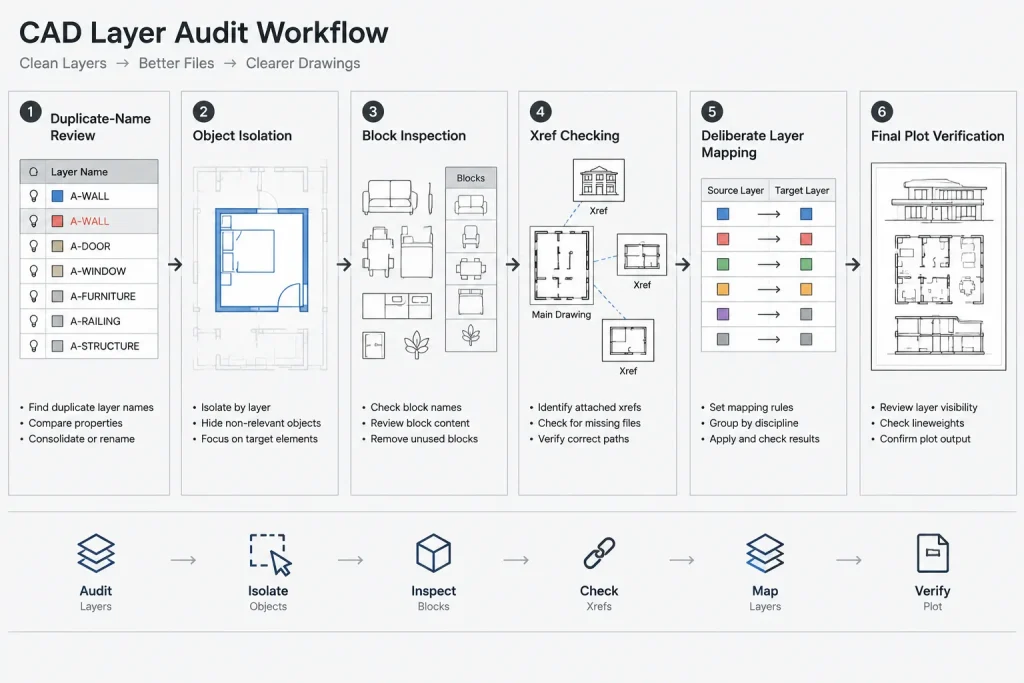
Layer cleanup should begin with inspection rather than immediate deletion. A layer that appears unused may be referenced by a block, external reference, saved view, or another drawing-dependent object.
Use the following review sequence:
- Identify obvious duplicates. Look for alternate spellings, inconsistent abbreviations, and names that differ only by punctuation.
- Inspect layer content. Isolate questionable layers and determine what their objects represent.
- Compare properties. Layers with similar names may have intentionally different plotting or visibility settings.
- Review block contents. Geometry inside a block may use layers that are not obvious from the inserted block’s visible properties.
- Check xref dependencies. Referenced layers are controlled differently from native drawing layers.
- Map objects deliberately. Reassign content only after deciding which approved layer serves the same purpose.
- Verify representative sheets. Plot or preview plans, elevations, sections, and details after cleanup.
Build a Layer Standard That Can Grow
A successful system accommodates new information without forcing users to improvise. Establish approved major element terms, common modifiers, field order, separator rules, and status terminology. Then define who may add new layers and how additions are documented.
Templates should contain frequently used layers, but they do not need every layer that could ever appear. An oversized template can burden small projects with irrelevant choices. A better approach is to combine a controlled core list with approved project-specific additions.
Review the layer system at project milestones. If users repeatedly place objects on the wrong layer, the problem may be unclear training, but it may also indicate that two names are too similar or that the intended distinction has no practical value.
Layer Naming Quality-Control Checklist
- Every name follows the same field order and separator convention.
- Abbreviations have one documented meaning.
- Geometry and annotation are separated where view control requires it.
- Project status is identifiable without relying only on color.
- Layer properties support the intended plotted hierarchy.
- Temporary and nonplotting layers are clearly controlled.
- Consultant and xref layers remain identifiable.
- Blocks do not contain unexplained or incorrectly assigned layers.
- Duplicate and nearly duplicate names have been reviewed.
- Representative sheets have been checked after layer changes.
Architectural CAD layer naming is ultimately an information-management system. A concise, predictable convention helps users understand a DWG quickly, control drawing graphics, and exchange files with fewer surprises. The best framework is not the one with the most fields; it is the one the project team can apply consistently and verify throughout the drawing set.
Putting the Naming Framework into Practice
A layer convention is easier to adopt when it is tested on actual drawing tasks rather than developed only as a list of abbreviations. Begin with a representative plan, elevation, section, and detail. Identify which information must be controlled independently, then confirm that the proposed names remain understandable when sorted, referenced, plotted, and reviewed by someone who did not create them.
Create a Layer Decision Record
Document the reason for each major distinction in the layer system. The record does not need to repeat every layer name. It should explain decisions such as when annotation is separated from model geometry, how project status is represented, which layers are nonplotting, and how consultant information is handled.
This decision record helps prevent future users from creating nearly duplicate layers because they do not understand the intended purpose of an existing one.
Test Common Drawing Operations
- Isolation: Confirm that users can isolate a building element without retaining unrelated notes or graphics.
- Sheet preparation: Check whether annotation and model information can be displayed appropriately for different drawing types.
- Reference coordination: Review how names appear when architectural and consultant files are attached together.
- Plot review: Confirm that layer properties create the intended graphic hierarchy without widespread object-level overrides.
- File handoff: Ask a user unfamiliar with the file to identify representative content from the layer names alone.
Define an Exception Process
Some projects require information that the core layer list did not anticipate. Instead of forcing that content onto an unsuitable layer or allowing uncontrolled names, provide a simple review process for project-specific additions. Each new layer should have a distinct purpose, follow the established field order, and be added to the project documentation.
Measure Clarity Through Use
A naming system should be revised when it repeatedly causes misclassification, requires frequent explanation, or produces layers that users cannot distinguish. The goal is not absolute uniformity at the expense of usability. The goal is a stable vocabulary that supports drafting, coordination, plotting, and long-term file maintenance.
Frequently Asked Questions
Is there one correct architectural CAD layer naming system?
No single pattern fits every office or project. The most appropriate system is the one that satisfies applicable project requirements and consistently supports visibility, plotting, coordination, and editing. If a client or project agreement specifies a convention, follow that requirement.
Should every object type have a separate layer?
No. Create a separate layer when information requires independent visibility, ownership, status, or graphic treatment. Excessive subdivision can make a drawing as difficult to manage as placing unrelated objects together.
Should annotation and building geometry share layers?
They should be separated when they need different visibility or plotting control. For example, a building element may appear in several views while its tag or note is relevant only to a particular presentation.
How should renovation status be included in layer names?
Use a documented status field or another consistent project-wide structure. The name should make the condition understandable without relying only on display color or an object override.
Should consultant layers be renamed?
Not without an established exchange procedure. Uncontrolled renaming can make updated files difficult to compare and coordinate. If conversion is necessary, perform it on a controlled copy and document the mapping.
Why do duplicate layers appear in a DWG file?
Common causes include inconsistent abbreviations, imported content, copied objects, block definitions, consultant files, and project-specific additions made without review. Inspect the content and dependencies before merging or removing any layer.
When should a layer standard be reviewed?
Review it when project requirements change, coordination problems recur, users frequently misclassify objects, or drawing cleanup reveals repeated duplicate names. Project milestones also provide useful opportunities to verify representative sheets.