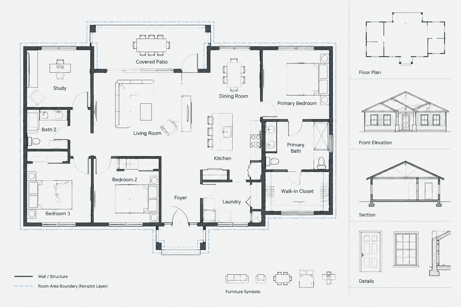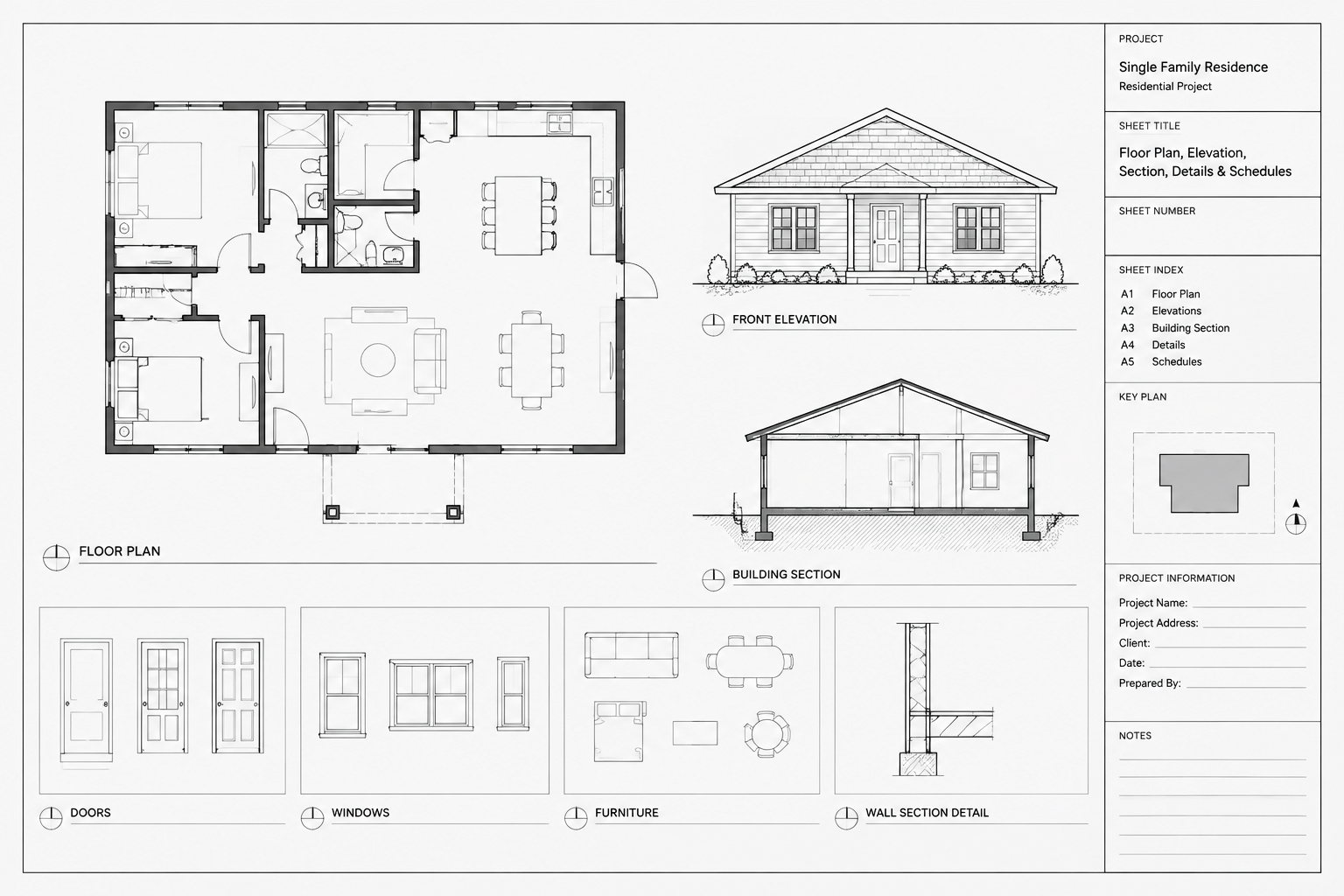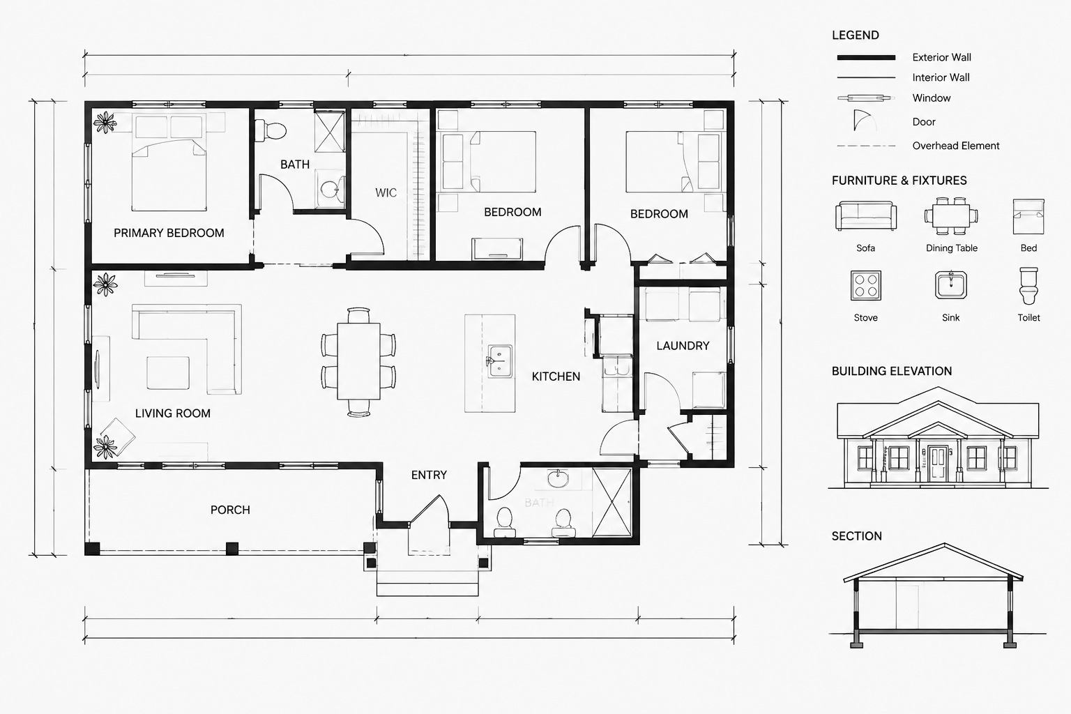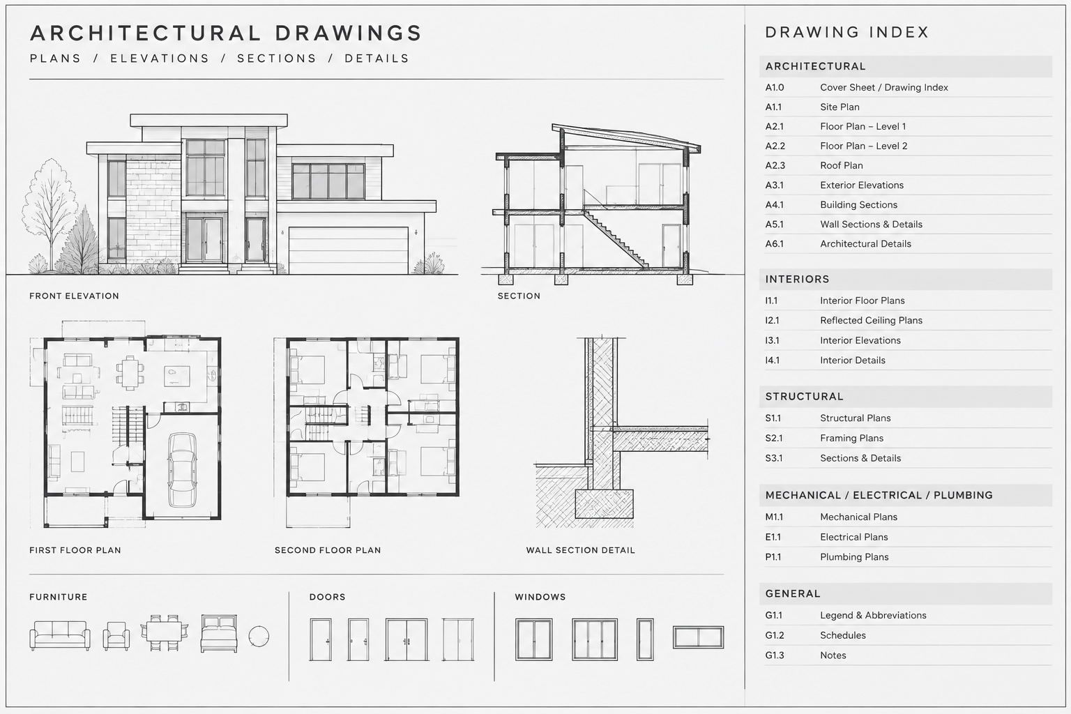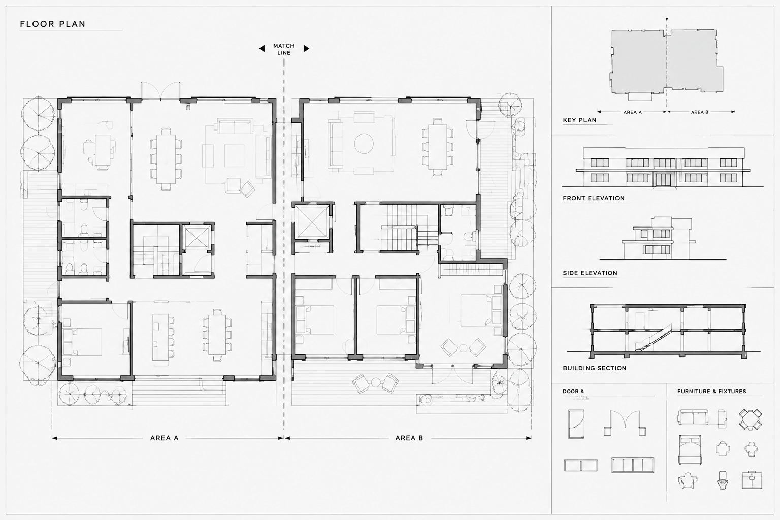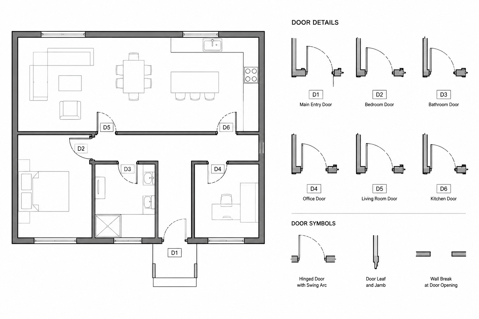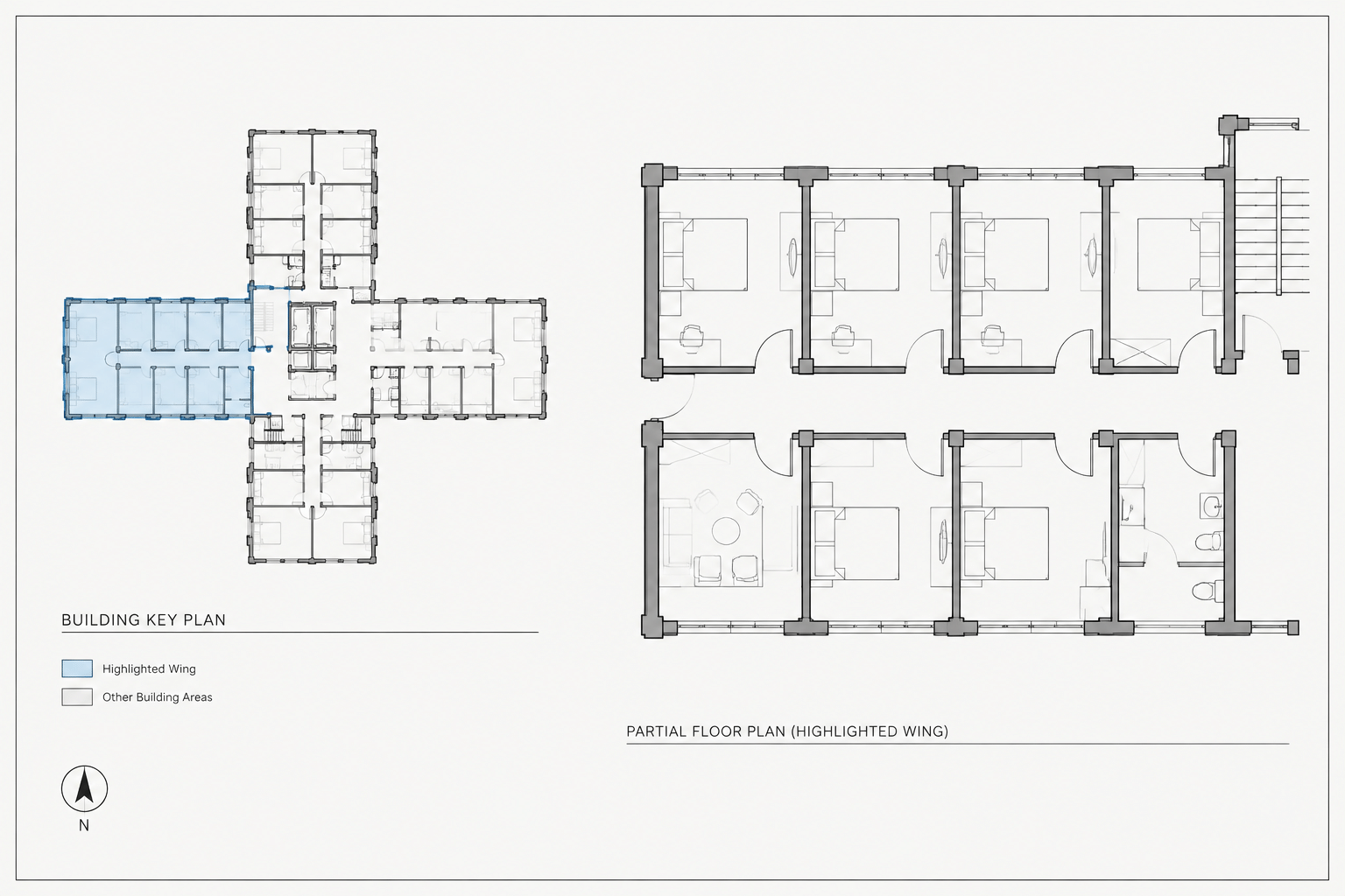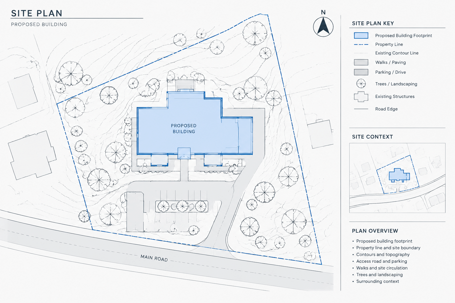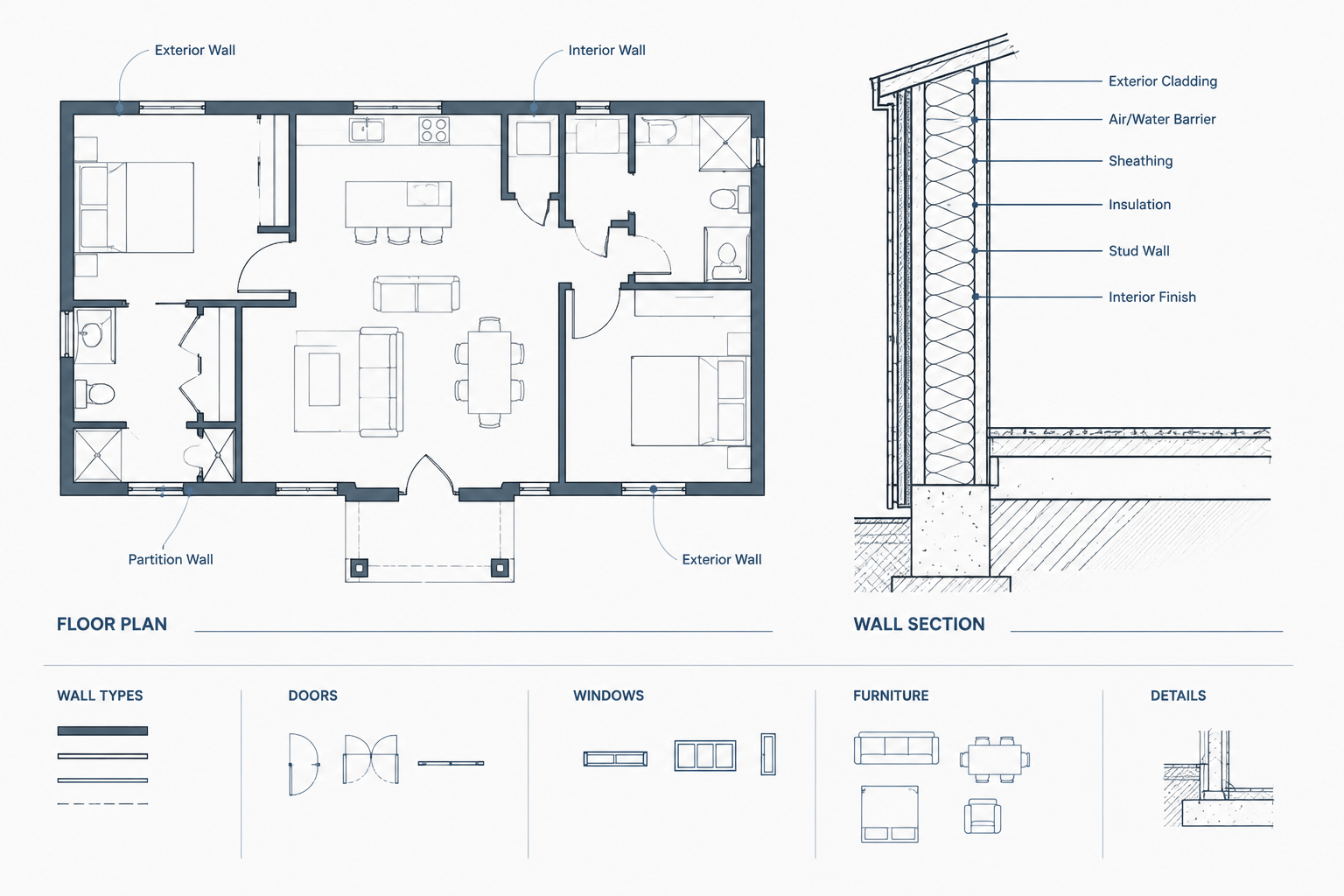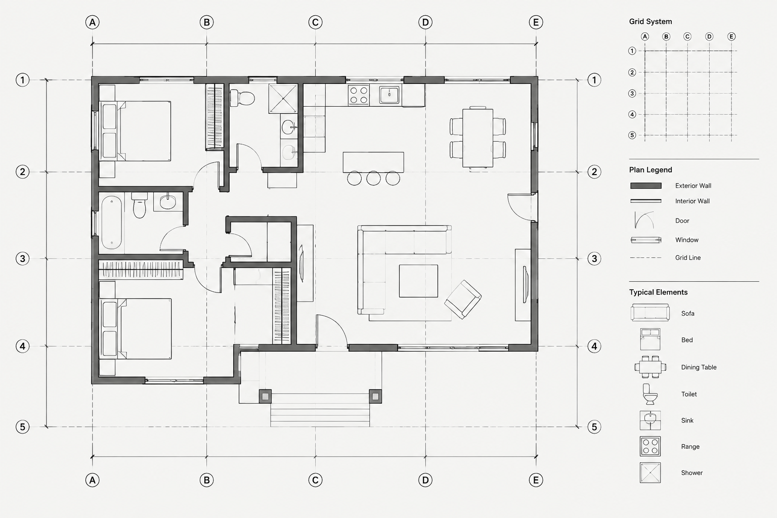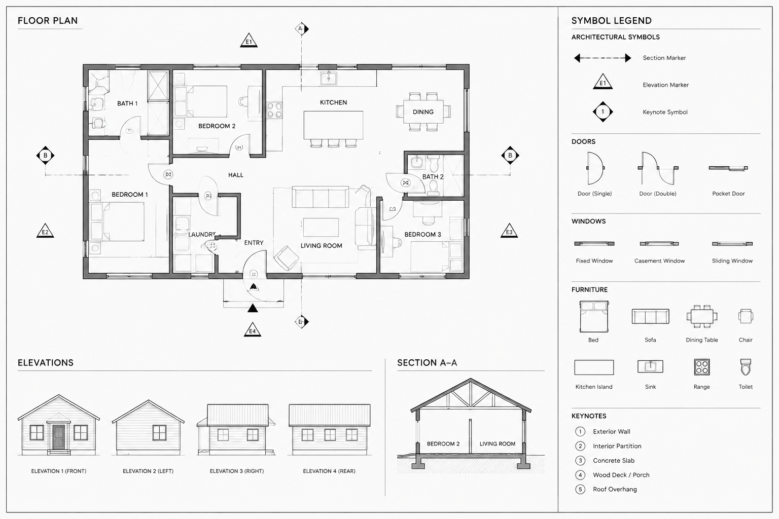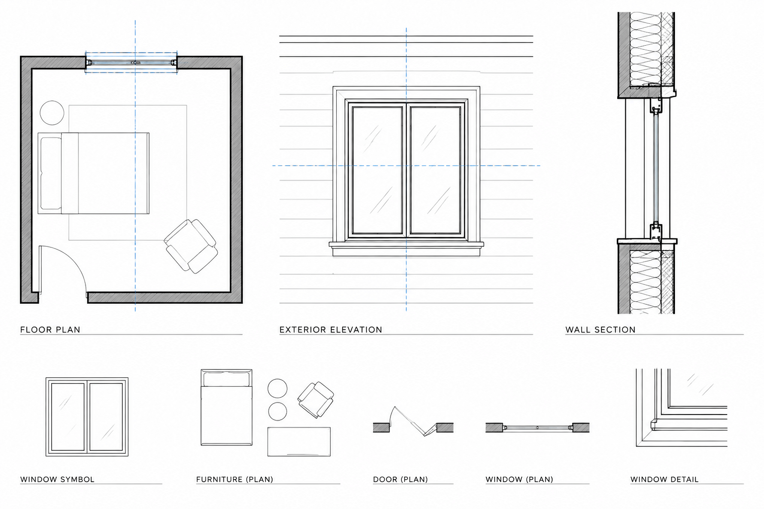
Windows appear in several drawing views, but they should describe one coordinated building element. A window shown in plan establishes its location within the wall. The elevation communicates its visible proportions and composition. A section explains its vertical relationship to the wall, floor, sill, and head. If these views are drafted independently, even small changes can produce conflicting openings, tags, or alignments.
A reliable CAD workflow treats the window as coordinated information rather than three unrelated symbols. The exact frame profile, installation detail, glazing specification, and opening size must still come from verified project and product information. The drafting methods below focus on organizing and coordinating that information clearly.
Start with verified window information
Before drawing window geometry, identify what is known and what remains unresolved. A design-phase window may only have an intended location and approximate proportion. A developed construction drawing may need to reflect a selected frame, wall assembly, operation, and manufacturer-defined opening requirements.
Useful source information may include:
- The architectural floor plan and wall type
- Exterior and interior elevations
- Building sections and wall sections
- The window schedule and type designations
- Verified manufacturer drawings or product data
- Structural opening information provided by the responsible consultant
- Project-specific sill, head, jamb, flashing, and trim requirements
Do not assume that the nominal window designation equals the framed opening. Frame dimensions, installation clearances, accessory profiles, and surrounding construction vary. Keep unverified information visibly separate from approved project data.
Establish a consistent window reference
Choose a stable reference that can be recognized in every view. Depending on the project, this may be the window centerline, the edges of the opening, a frame datum, or the face of an adjacent wall. The important point is consistency.
A centerline is useful for locating repeated windows and checking symmetry. Opening edges are often more useful when coordinating masonry, framing, finishes, or adjacent elements. In section, a sill datum can help coordinate the window with floor levels and interior features.
Avoid locating the plan symbol from one reference while dimensioning the elevation from another unless the relationship is deliberate and documented. Mixed references make later revisions difficult to track.
Drafting the window in plan
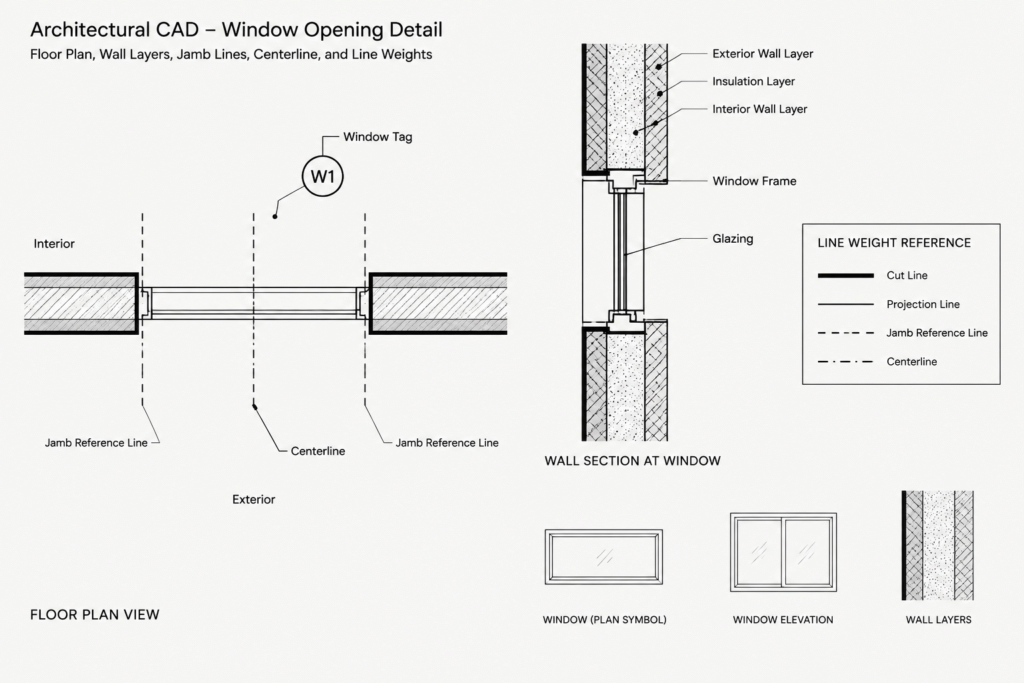
The plan view primarily communicates where the opening occurs, how it relates to the wall, and what type of window is intended. The amount of frame and sash detail should match the drawing scale and purpose.
Build the wall opening first
Begin with the coordinated wall geometry. Create the opening using verified jamb locations rather than placing a generic window block and stretching the wall around it. This keeps the wall and opening dimensions authoritative.
Check the opening against nearby corners, columns, doors, casework, fixtures, and room dimensions. Also confirm that the opening does not accidentally interrupt wall elements that continue above or below the plan cut.
Show only useful frame information
At a general floor-plan scale, a simplified frame and sash symbol is usually clearer than a product-level profile. Use enough linework to distinguish the window from the wall and to communicate its basic operation when that information is relevant.
Complex frame extrusions, seals, fasteners, and flashing components generally belong in enlarged details. Excessive geometry can merge when plotted and make the opening harder to read.
Apply the project cut convention
A plan is a horizontal cut through the building, but the graphic treatment of windows depends on the project convention and the location of the cut relative to the opening. Decide which elements are cut, visible beyond, overhead, or hidden, and assign their lineweights or linetypes accordingly.
For windows above the normal plan cut, such as clerestory units, use the office convention for overhead information. Do not draw them like ordinary cut openings if that would misrepresent their position.
Add tags without obscuring the opening
Place the window tag close enough to be associated with the correct unit but outside dense frame, wall, and dimension linework. The tag should match the identifier used in the schedule and related views. When several windows are close together, leaders or a carefully organized tagging pattern can prevent ambiguity.
Projecting the window into elevation
Once the plan location is established, use projection or construction lines to transfer jamb positions into the relevant elevation. This is more dependable than redrawing the window by eye.
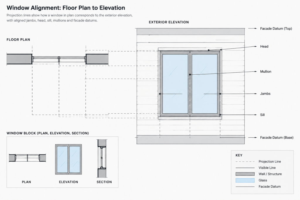
Coordinate the horizontal extent with the plan and establish the vertical extent from verified sill and head information. Then add frame, sash, mullion, transom, panel, or glazing lines as required by the design.
Use an elevation hierarchy
The outline of the opening and major frame divisions should read before secondary profiles. Visible edges can be lighter than the primary building silhouette, while distant or internal glazing lines should not overpower the facade.
Operation symbols may be included when required by the office standard or drawing purpose. Use them consistently and explain unfamiliar symbols in a legend. Do not rely on operation marks alone when the schedule must identify the actual window type.
Check repeated alignments
Windows that appear aligned should be checked rather than assumed to align. Compare jambs, centers, heads, sills, mullions, floor levels, and adjacent facade elements. Slight inconsistencies are particularly noticeable across repeated bays.
If an intentional offset exists, make it clear enough that it does not look like a drafting error. Relevant dimensions, datums, or notes should explain the design relationship.
Developing the window in section
A section should connect the window to the building assembly. Start by projecting the window location from the plan and transferring the sill and head from the coordinated elevation or section datum.
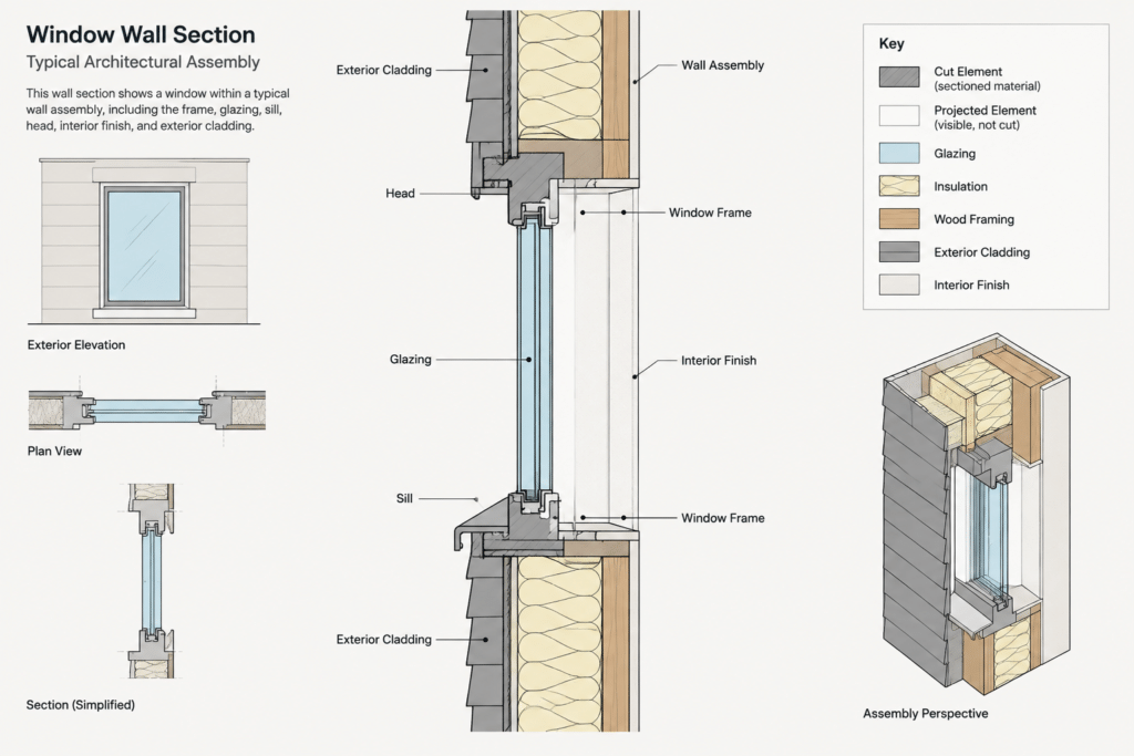
At a general building-section scale, show the opening, principal frame position, glazing location, and relationship to floors or roofs. At a larger scale, the section may also show trim, returns, substrate transitions, insulation continuity, flashing concepts, and adjacent finishes. The final detail must be based on verified assembly and product information.
Distinguish cut and projected elements
Elements cut by the section plane need stronger graphic emphasis than components seen beyond. Use poché or material hatching where appropriate, but keep frame and glazing lines legible. Avoid filling small profiles with so much hatch that their boundaries disappear.
Coordinate sill and head conditions
The section should show how the sill relates to interior finishes, exterior drainage, wall thickness, and any adjacent casework or ledges. At the head, coordinate the frame with structure, lintels, cladding support, ceilings, shades, or other nearby construction.
These relationships are project-specific. A generic CAD detail can be a starting reference, but it should not be treated as a verified installation detail without review.
Coordinate window information across drawings
| Drawing view | Primary information | Coordination check |
|---|---|---|
| Floor plan | Location, opening, wall relationship, tag | Compare jambs, wall type, and nearby dimensions |
| Exterior elevation | Proportion, head, sill, frame divisions, appearance | Compare width with plan and vertical position with section |
| Interior elevation | Relationship to finishes, casework, and interior features | Confirm sill, trim, and adjacent element clearances |
| Building section | Vertical location and relationship to major assemblies | Confirm levels, head, sill, floor, and roof conditions |
| Enlarged detail | Assembly interfaces and component relationships | Verify against wall type and selected product information |
| Window schedule | Type identifier and scheduled attributes | Confirm every tag and avoid duplicate identifiers |
When a window changes, review every view where it appears. A simple revision checklist can include the plan opening, exterior elevation, interior elevation, sections, details, schedule, dimensions, notes, and tags.
Organize window geometry in the CAD file
Place window objects on layers that follow the project CAD standard. Separate annotation from model geometry so tags and notes can be controlled independently. If overhead windows, demolition conditions, or secondary profiles require distinct graphics, use dedicated layers rather than manually overriding random objects.
Reusable window blocks can improve consistency, but avoid creating a separate block for every minor variation without a clear naming system. Define a logical insertion point, such as the center of the opening or a jamb reference, and document that choice. A block inserted from an unknown point is difficult to align accurately.
Keep blocks at the intended drawing units and confirm their scale before use. Avoid scaling a window unevenly merely to make it fit an opening; distorted frames and operation symbols can conceal a coordination problem. Edit or replace the source geometry using verified dimensions instead.
Common window drafting errors
- Plan and elevation widths disagree: Project jamb locations rather than estimating the elevation.
- Tags do not match the schedule: Use one controlled identifier for each scheduled type or unit, according to the project method.
- Generic blocks contain excessive detail: Simplify geometry to suit the view and plotting scale.
- Head and sill positions drift between elevations and sections: Reference shared levels or construction datums.
- Frame depth conflicts with the wall: Verify the selected system and wall assembly instead of stretching a symbolic block.
- Overhead windows look like cut openings: Apply a distinct overhead convention.
- Revision clouds address only one view: Search the drawing set for every instance of the affected tag.
A practical quality-control pass
Begin with a visual review of the entire facade and plan. Look for broken alignments, inconsistent frame divisions, crowded tags, and unexpected lineweights. Then perform a focused check by window identifier, comparing each occurrence with the schedule and relevant details.
Finally, review the plotted sheet rather than relying only on the model-space display. Confirm that glazing, frames, wall cuts, operation symbols, tags, and dimensions remain distinguishable at the intended output scale. A coordinated window drawing should communicate location, appearance, and assembly relationships without requiring the reader to resolve contradictions between views.