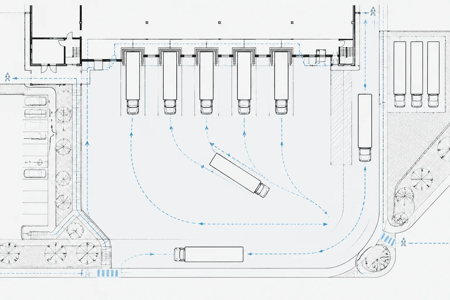
Vehicle turning paths in architectural CAD help the project team test whether entrances, drive aisles, drop-off areas, loading zones, gates, and service routes can support the intended vehicle movement. A useful study combines a current site-plan background with verified vehicle geometry, a readable swept envelope, and clear documentation of assumptions.
The following workflow explains how to prepare, review, and coordinate turning-path graphics without confusing conceptual drafting with specialist vehicle simulation. It also highlights the site elements and operational conditions that should remain visible when evaluating a maneuver.
Vehicle circulation can appear workable on a site plan while still containing conflicts that become obvious only when a design vehicle is tested through the route. A curb return may be too tight, a loading approach may require an unrealistic maneuver, or a drop-off lane may place turning vehicles near columns, walls, gates, or pedestrian areas.
Architectural CAD drawings should communicate these issues clearly without presenting an approximate turning diagram as a certified vehicle simulation. The objective is to establish a traceable design vehicle, draw or import its movement accurately, identify conflicts, and coordinate the results with the site plan and relevant consultants.
What a vehicle turning-path study should show
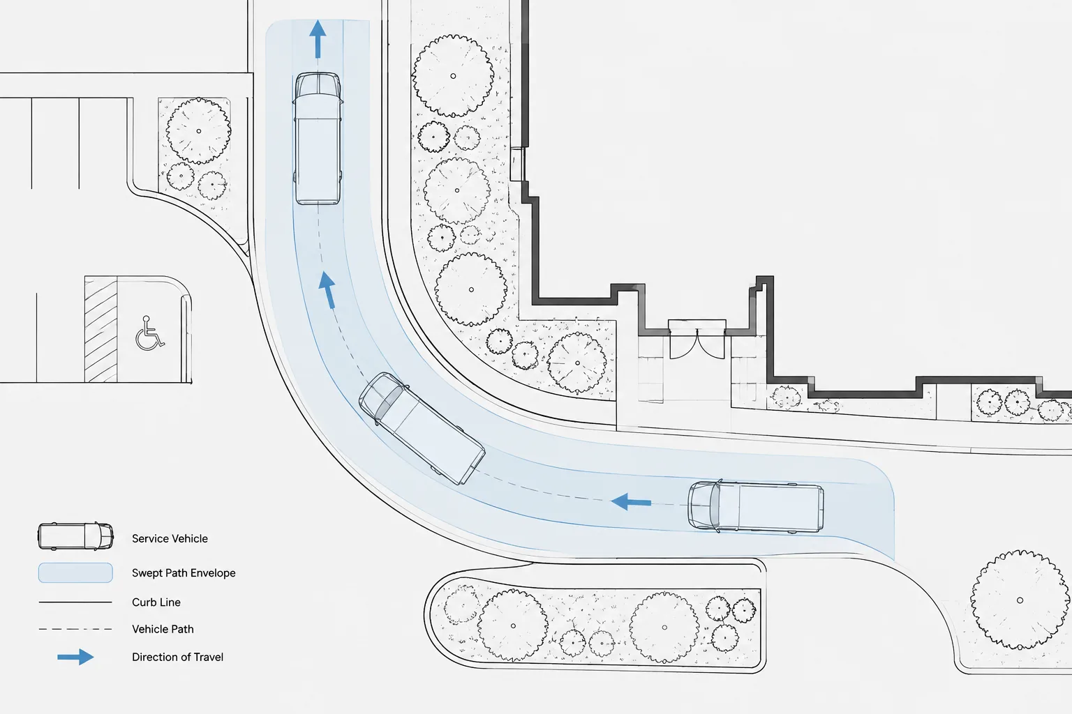
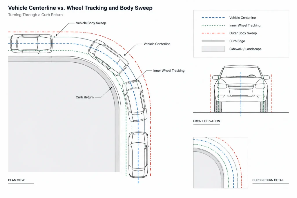
A useful turning-path study represents more than the centerline followed by the driver. Depending on the purpose of the drawing, it may need to show:
- The path followed by the selected vehicle.
- The outer sweep of the vehicle body.
- The inner wheel or body path where off-tracking occurs.
- The vehicle at critical positions along the maneuver.
- Direction-of-travel arrows.
- Forward and reverse movements.
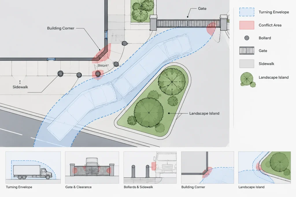
- Nearby curbs, walls, columns, gates, islands, parking spaces, and loading equipment.
- Pedestrian crossings, sidewalks, entrance zones, and other areas requiring coordination.
The turning envelope is generally more important than a single travel line. A route centerline can clear an obstruction while the front or rear of the vehicle crosses it. Long or articulated vehicles may also track substantially differently from passenger vehicles.
Start with a verified design vehicle
Do not select a vehicle block merely because it looks appropriate. The study should be based on a design vehicle identified by the project team, owner, operator, transportation consultant, civil engineer, or applicable reviewing authority. Examples may include a passenger vehicle, delivery vehicle, refuse vehicle, emergency vehicle, shuttle, bus, or another project-specific vehicle.
Before using a template or block, confirm:
- The source of the vehicle geometry.
- The drawing units and insertion scale.
- Whether the geometry represents the body, wheels, axles, or a complete swept-path envelope.
- Whether the turning assumptions match the intended maneuver.
- Whether attachments, mirrors, lifts, trailers, or other projections are represented when relevant.
A generic CAD block downloaded for graphic presentation should not automatically be treated as a reliable turning template. If the source and assumptions cannot be verified, label the study as preliminary and seek project-specific confirmation.
Prepare the site-plan background
Vehicle studies are easiest to coordinate when the site geometry is clean and current. Reference the civil or architectural site plan rather than copying its contents into an isolated file. Confirm that the reference uses the correct units, project coordinates, orientation, and revision.
Keep the following elements visible during the review:
- Face of curb and curb transitions.
- Building walls, canopies, and projecting elements.
- Columns, bollards, gates, fences, and guard features.
- Parking spaces, drive aisles, ramps, and medians.
- Loading bays, dock equipment, and service enclosures.
- Property or operational limits relevant to the maneuver.
- Sidewalks, crossings, doors, and pedestrian waiting areas.
Avoid testing the vehicle against a simplified paving outline if detailed curb, structural, or equipment geometry is available. Small plan differences can affect a tight maneuver.
Organize the CAD layers
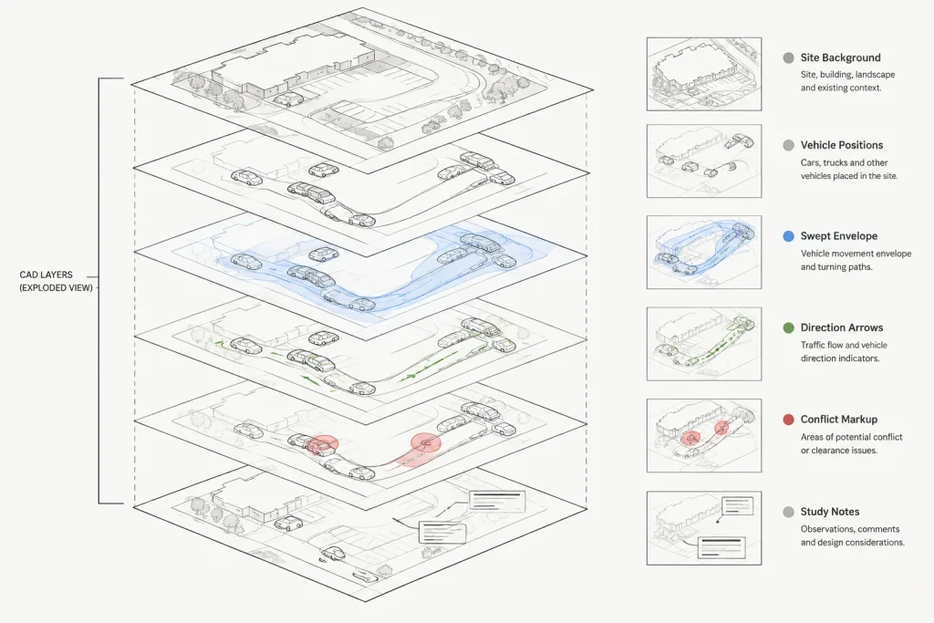
Separate vehicle-analysis graphics from permanent site-plan geometry. This allows the study to be displayed on coordination sheets without affecting the underlying plan.
| Graphic content | Suggested purpose |
|---|---|
| Vehicle positions | Shows the design vehicle at selected points in the maneuver. |
| Swept envelope | Shows the combined area occupied during movement. |
| Wheel or reference paths | Explains how the envelope was generated or interpreted. |
| Direction arrows | Distinguishes entry, exit, forward, and reverse travel. |
| Conflict markup | Highlights locations requiring design review. |
| Study notes | Records vehicle source, assumptions, status, and limitations. |
Use layer names that fit the project CAD standard. Give analysis graphics a clear visual hierarchy so that the curb and building geometry remain readable beneath them.
Choose an appropriate analysis method
Specialized swept-path software
Dedicated vehicle-tracking software can calculate movement from vehicle parameters and steering behavior. When the project depends on precise operational verification, an appropriate specialist and validated tool may be necessary. Save enough information to identify the vehicle and assumptions used, rather than plotting an unexplained envelope.
Verified manufacturer or agency templates
A verified template may be inserted and positioned through a sequence of movements. Confirm its intended use and units before relying on it. A static turning template may illustrate a particular maneuver but may not represent every steering transition or operational condition.
Manual CAD studies
Manual studies using blocks, arcs, polylines, and offsets can be useful during early planning. However, simply rotating a vehicle block around an arbitrary point does not reproduce realistic steering, wheel paths, or off-tracking. Treat manually constructed envelopes as conceptual unless their method has been checked by a qualified party.
A practical drafting workflow
1. Define the maneuver
Mark the starting position, destination, direction of travel, and any required stopping or reversing points. Determine whether the study covers entry, exit, internal circulation, parking, loading, or a complete route.
2. Place the vehicle in critical positions
Show the vehicle at locations where clearance appears most constrained. Common examples include a gate, curb return, ramp transition, loading bay approach, building corner, column line, or turnaround point. Do not fill the drawing with so many positions that the envelope becomes unreadable.
3. Generate or import the swept envelope
Use the verified method selected for the project. Keep the body envelope distinct from reference paths. If reverse movement is included, differentiate it graphically and show where the direction changes.
4. Review the full occupied area
Check the envelope against more than curbs. Review walls, canopy supports, bollards, parked vehicles, doors, gate leaves, equipment pads, landscape islands, and pedestrian routes. Also consider whether the source study accounts for relevant projections beyond the basic wheel path.
5. Mark conflicts without hiding them
Use a dedicated markup layer or revision copy to identify overlaps and narrow points. Avoid trimming an envelope merely to make it fit the design. If a conflict results in a site change, update the base geometry and rerun the maneuver.
6. Add concise study notes
Identify the design vehicle, information source, direction of travel, drawing status, and any important assumptions. If the study is preliminary or diagrammatic, say so directly. Do not imply approval by an authority, operator, or emergency service unless that approval has actually been obtained and documented.
Coordinate the route as an operational sequence
A turning path can fit geometrically but still function poorly. Review the complete sequence of use. A delivery vehicle may clear the curb yet block an entrance while unloading. A refuse vehicle may reach an enclosure but require backing through a pedestrian crossing. A drop-off loop may accommodate a single moving vehicle while queued vehicles occupy the turning area.
Discuss the study with the disciplines and stakeholders responsible for the surrounding conditions. Coordination may involve civil grading, landscape islands, structural columns, gate hardware, site lighting, signage, drainage structures, loading operations, and pedestrian planning. The architectural CAD file should record agreed geometry, but it should not substitute for specialist review where that review is required.
Common CAD mistakes
- Using an unverified vehicle block: A presentation symbol is not necessarily a turning template.
- Testing only the vehicle centerline: The body and wheel envelopes may extend well beyond it.
- Ignoring reverse travel: Some service routes depend on backing movements that should be shown explicitly.
- Moving the site plan to make the test fit: Preserve the coordinated project origin and revise geometry through the normal design process.
- Exploding imported results unnecessarily: Maintain editable, identifiable study geometry when practical.
- Reviewing an obsolete background: A valid study against an old curb layout is not useful.
- Plotting every analysis line equally: Poor hierarchy can hide both conflicts and permanent site features.
- Omitting assumptions: Future users may mistake a conceptual diagram for verified analysis.
Quality-control checklist
- Is the design vehicle identified and appropriate for the intended operation?
- Have the source, units, and scale of the vehicle data been checked?
- Is the site-plan reference current and correctly aligned?
- Are outer sweep, inner tracking, and critical vehicle positions understandable?
- Are forward and reverse movements clearly distinguished?
- Have curbs, structures, equipment, parked vehicles, and pedestrian areas been reviewed?
- Are conflicts visible rather than concealed by draw order or hatching?
- Were revised layouts retested after geometry changed?
- Does the drawing state whether the study is preliminary, coordinated, or independently verified?
Make the study traceable
A well-drafted turning-path study allows another team member to understand what was tested, which background was used, and where the design remains constrained. Keep analysis graphics on controlled layers, retain the verified vehicle information, and archive significant study iterations when they support design decisions.
Most importantly, treat the swept path as a coordination tool rather than decorative site-plan graphics. Clear assumptions, reliable source geometry, and review of the entire operating route make the CAD study useful to architects, consultants, owners, and field teams.
How to use the turning-path drawing during coordination
The value of a turning-path drawing depends on how clearly it supports a design decision. Before issuing the study, identify the question being tested: whether a vehicle can enter, reach a destination, turn around, load or unload, and leave without conflicting with fixed or operational site elements.
Present the result at a scale and graphic hierarchy that make the constrained areas easy to inspect. Permanent site geometry should remain legible beneath the analysis, while the swept envelope, vehicle positions, travel direction, and conflict markup should be visually distinct. Notes should identify the study status and the source of the vehicle information without overstating the level of verification.
Separate geometric clearance from operational approval
A clear envelope indicates what the selected analysis represents, but it does not by itself confirm that the complete operation is acceptable. Queuing, temporary obstructions, parked vehicles, open gates, loading activity, pedestrian movement, access control, and changes in grade may affect how the route functions. These conditions should be reviewed with the appropriate project participants.
Maintain a reliable revision trail
When curbs, walls, columns, islands, gates, or equipment locations change, treat the previous turning study as superseded until the maneuver has been tested again. Retain enough file information to distinguish current results from earlier options. This prevents an outdated envelope from being reused on a revised background.
Prepare the drawing for review
- Display the complete maneuver rather than an isolated turn.
- Keep critical site features visible and correctly aligned.
- Distinguish vehicle positions from the combined swept envelope.
- Show direction changes and reversing movements clearly.
- Call out conflicts without altering or concealing the analysis geometry.
- State whether the result is conceptual, coordinated, or based on specialist analysis.
- Record unresolved questions for the responsible consultant, operator, or reviewer.
Frequently asked questions
Is a vehicle CAD block enough to create a turning-path study?
Not necessarily. A typical vehicle block may be intended only for plan presentation. A turning study requires geometry or analysis based on an identified design vehicle, known units, and documented movement assumptions.
What is the difference between a travel line and a swept envelope?
A travel line represents a selected reference path. The swept envelope represents the area occupied by the vehicle as it moves. Vehicle corners, body overhangs, wheels, or articulated portions may extend beyond a simple reference line.
Should vehicle turning paths appear on the main site plan?
They may be shown on a coordination view, study sheet, or controlled overlay, depending on the project workflow. Keeping the analysis on separate layers allows it to be displayed when needed without making permanent site geometry difficult to read.
When should a turning-path study be rerun?
Rerun the relevant maneuver whenever coordinated geometry or operating assumptions change in a way that could affect clearance. Examples include revised curbs, islands, columns, gates, parking layouts, loading equipment, or vehicle selection.
Can manual CAD drafting replace specialized vehicle-tracking analysis?
Manual drafting can support early planning and comparison, but it should not be presented as validated simulation unless its method and assumptions have been appropriately checked. Projects requiring precise operational verification may need specialist analysis.
What information should accompany the final graphic?
Identify the design vehicle, source information, direction of travel, relevant assumptions, background revision, and study status. The drawing should also make conflicts and unresolved coordination items visible.