Door hardware coordination in CAD is primarily an information-management task. The goal is not to draw every component, but to ensure that each opening can be traced consistently from the floor plan to its door schedule entry, hardware set, supporting details, specifications, and consultant documents.
The following workflow explains how to organize that information, identify discrepancies, and review changes without creating duplicate door data. Product selection, code compliance, mounting requirements, and system interfaces still require project-specific verification by the responsible professionals.
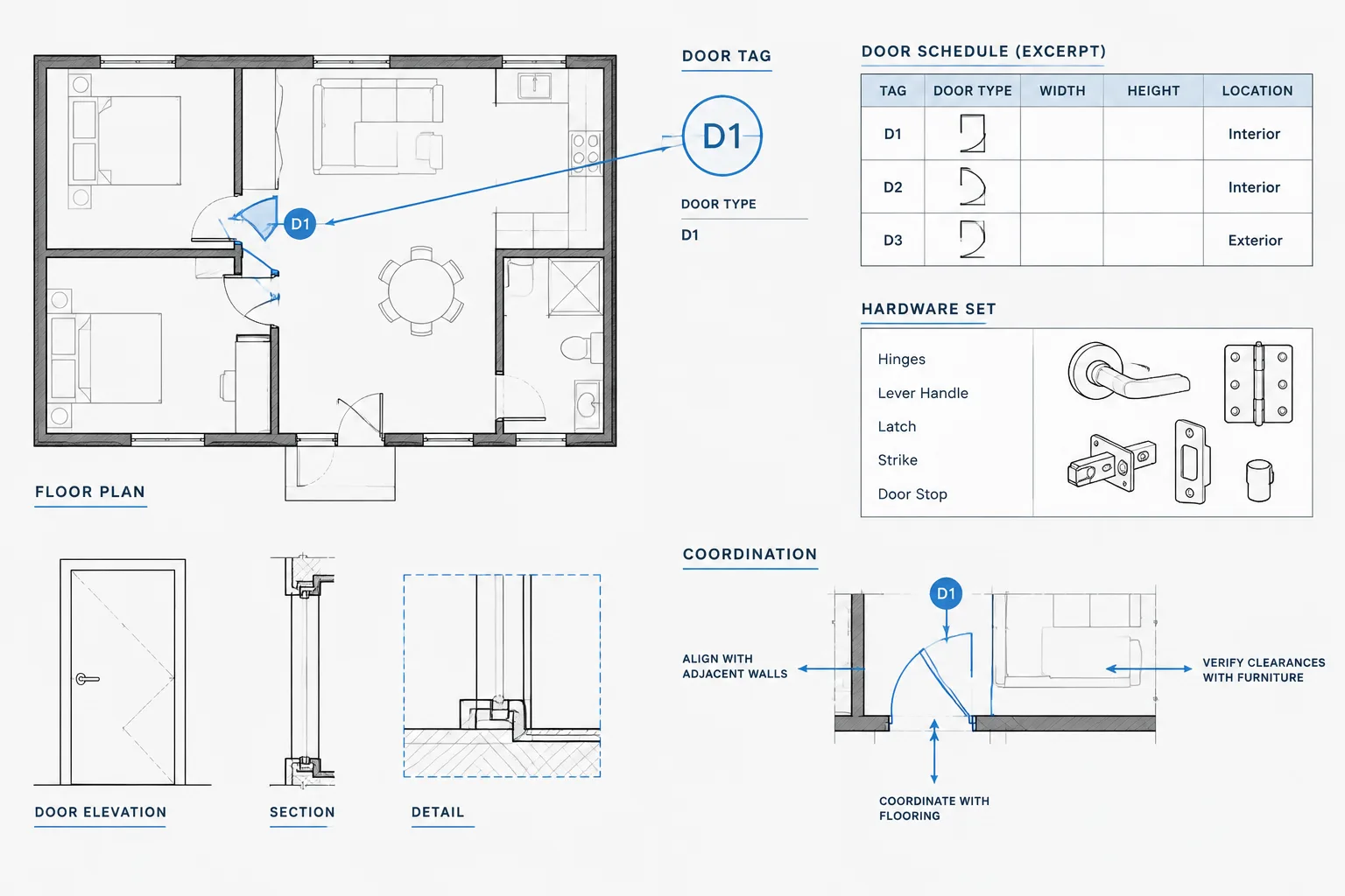
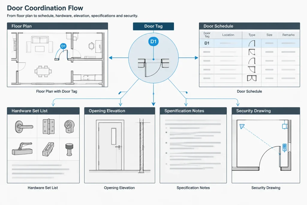
Door hardware is rarely communicated by drawing every hinge, latch, closer, seal, and access-control device on the floor plan. Instead, architectural drawings connect several layers of information: the door opening, door identifier, door schedule, hardware set, elevations or details, and consultant requirements. Effective door hardware coordination in CAD depends on keeping those references aligned.
This workflow focuses on drawing organization and information control rather than hardware selection. Actual products, mounting conditions, accessibility provisions, fire and egress requirements, security functions, and electrical interfaces must be verified for the project by the responsible design professionals and applicable authorities.
Understand the door hardware information chain
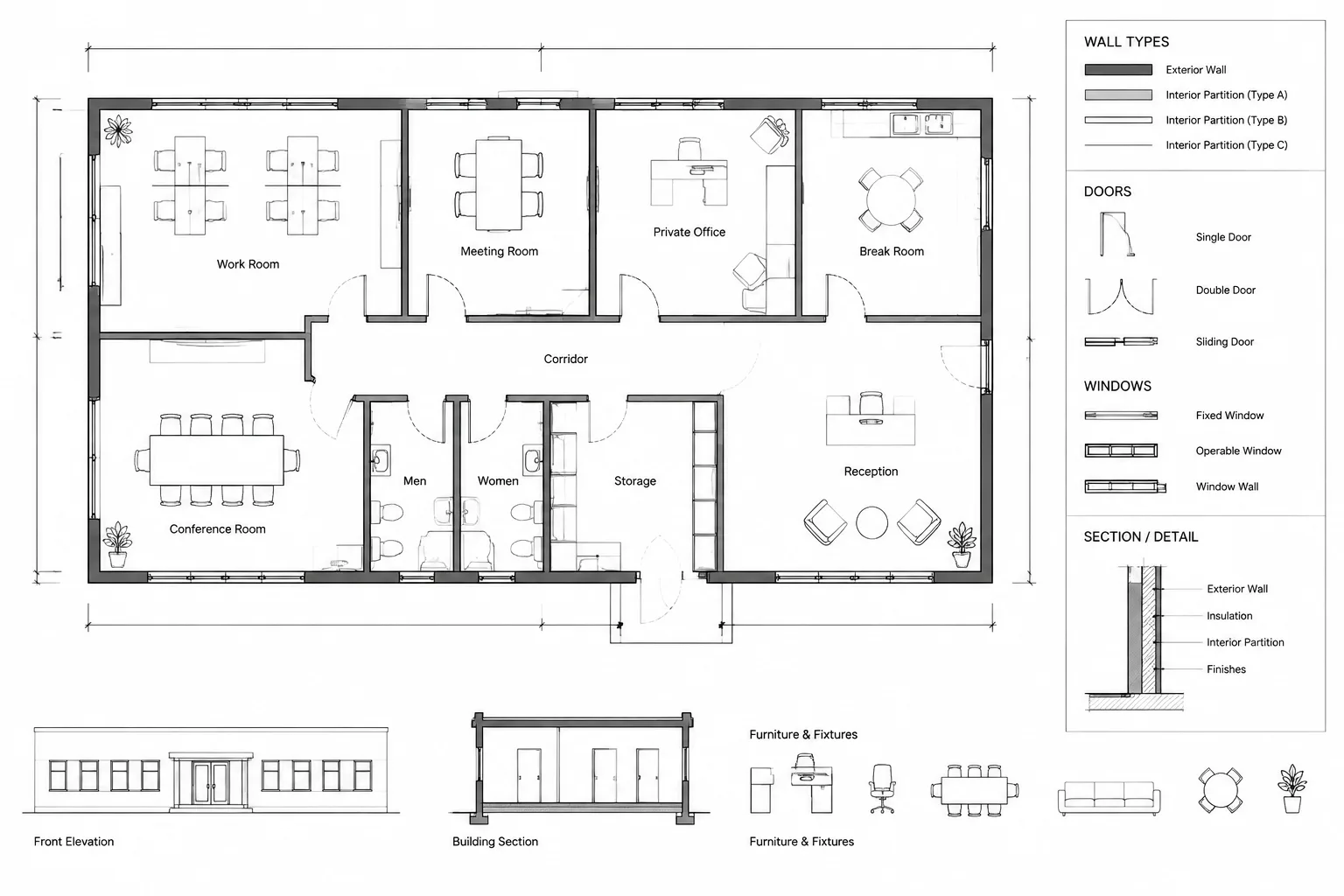
A door shown in plan is only the beginning of the information chain. The plan establishes the opening location, swing, and relationship to nearby construction. A door tag connects that opening to schedule data. The schedule identifies characteristics such as the door and frame types, while a hardware set groups the devices intended for an opening or category of openings.
Depending on the project delivery method, hardware information may be prepared by the architect, a hardware consultant, a specification writer, a supplier, a security consultant, or a combination of contributors. Before editing the CAD files, establish which document controls each field and who is responsible for approving changes.
| Information source | Primary purpose | Typical coordination question |
|---|---|---|
| Floor plan | Shows opening location, swing, tag, and spatial context | Is the door correctly placed and identified? |
| Door schedule | Organizes opening-specific information | Does every scheduled opening match a plan tag? |
| Hardware set list | Groups hardware by opening function or condition | Is the assigned set appropriate for the opening? |
| Elevations and details | Clarify frame, glazing, wall, and mounting relationships | Is there enough physical space for the intended devices? |
| Security or electrical drawings | Show powered, monitored, and controlled interfaces | Are device locations and power requirements coordinated? |
| Specifications | Describe performance, products, execution, and responsibilities | Does the drawing terminology agree with the written requirements? |
Begin with a controlled door inventory
Create or review the project door inventory before assigning hardware information. Every physical opening that requires its own documentation should have a stable identifier. Avoid reusing identifiers after a door is removed unless the project’s established documentation procedure specifically permits it. Reuse can make consultant comments, submittals, and revision histories difficult to trace.
Compare the inventory against every relevant floor plan. Look for common discrepancies:

- A door symbol without a tag
- A schedule row with no corresponding plan opening
- The same identifier attached to different openings
- A changed swing that was not reflected in the schedule or hardware review
- Paired doors represented as a single leaf in one view
- Openings in enlarged plans that disagree with the overall plan
- Exterior, service, cabinet, access-panel, or specialty openings classified inconsistently
If the door schedule is maintained outside CAD, assign one source as the authoritative inventory and use exports or review copies for comparison. Avoid making independent changes in multiple files without a reconciliation step.
Draft plan graphics for coordination, not decoration
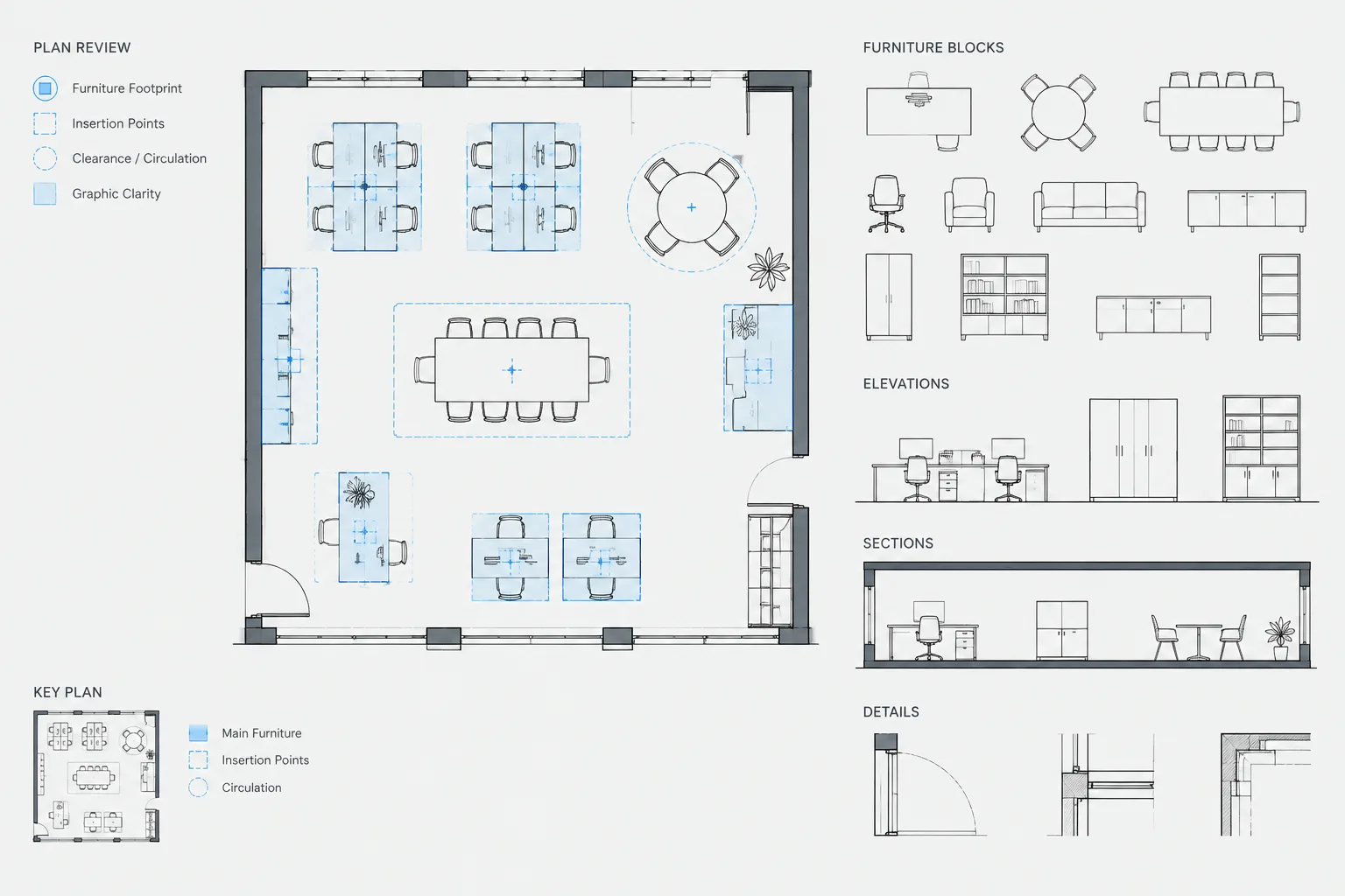
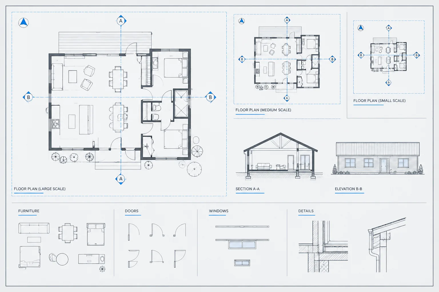
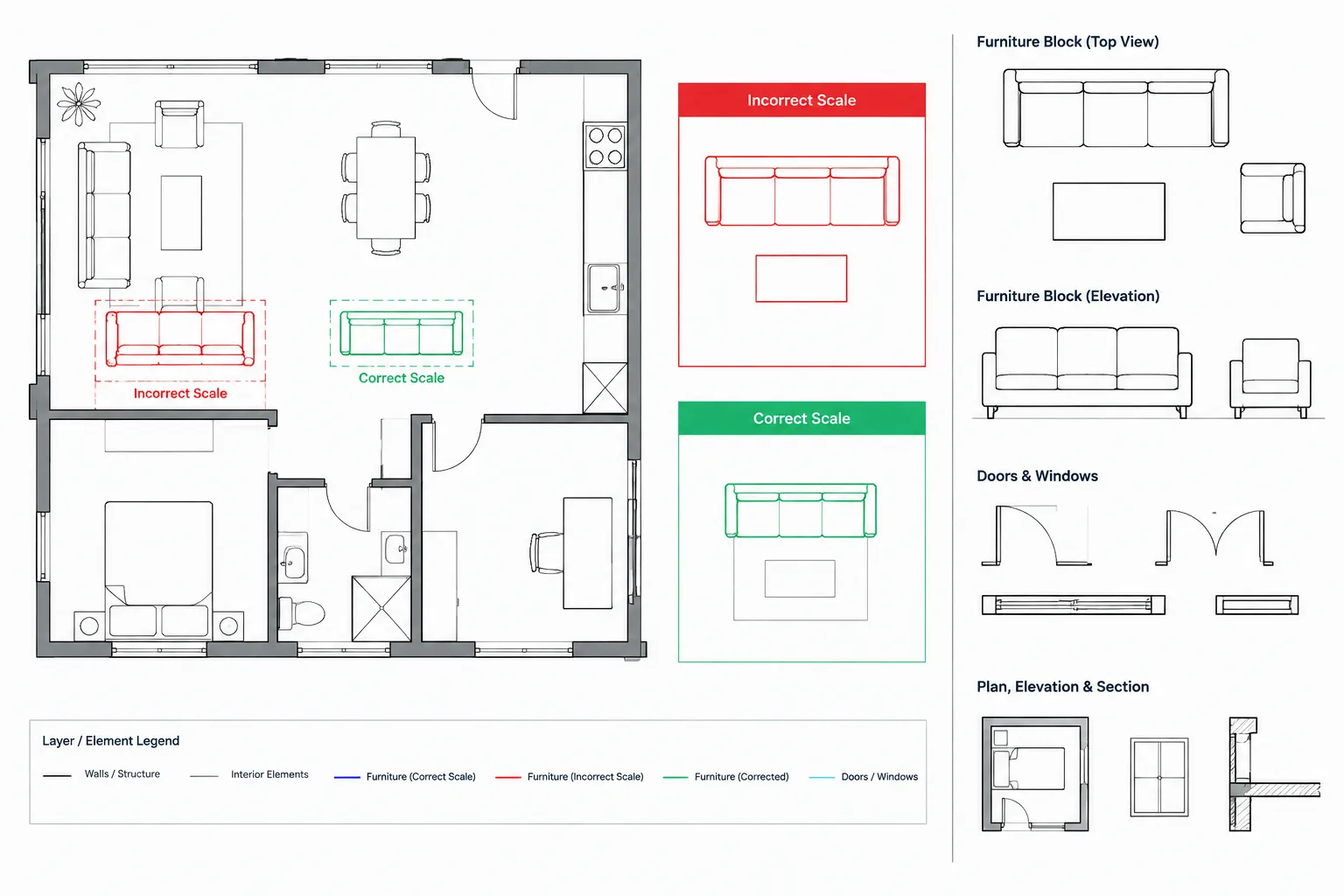
Door plan graphics should remain simple enough to read at the intended sheet scale. Show the wall opening, leaf or leaves, swing where applicable, and the door identifier. Additional symbols should be included only when they communicate information needed by the project team.
Hardware devices do not always need individual plan symbols. Adding every component can obscure walls, dimensions, and room information while creating another set of objects that must remain synchronized. Device symbols are more useful when location matters spatially or when another discipline must connect to them. Examples may include access-control devices, automatic operators, hold-open devices, or wall-mounted controls, subject to the project’s documentation approach.
Place such symbols on clearly named layers so they can be displayed in coordination views and suppressed where they would clutter general plans. Use a legend that distinguishes device types without implying a specific manufacturer or unverified product configuration.
Assign hardware sets consistently
A hardware set is a coordinated grouping of hardware for an opening condition. Similar-looking doors may require different sets because of operation, security, exposure, frame construction, adjacent rooms, or integration with other systems. Do not assign sets solely by door size or appearance.
Use a repeatable method when reviewing each opening:
- Identify the spaces or conditions on both sides of the opening.
- Confirm the intended direction of travel and door operation.
- Review whether the opening is interior, exterior, controlled, monitored, or otherwise specialized.
- Check the number of leaves and whether the leaves perform different roles.
- Confirm coordination with frame, glazing, wall, and ceiling conditions.
- Identify interfaces with power, controls, alarms, or security systems.
- Record unresolved decisions rather than guessing at a final set.
Keep the set identifier short and legible, but do not depend on color alone to distinguish status. A text-based status such as provisional, consultant review, revised, or confirmed is easier to track across printed and digital review methods.
Coordinate hardware with the physical opening
Check adjacent walls and objects
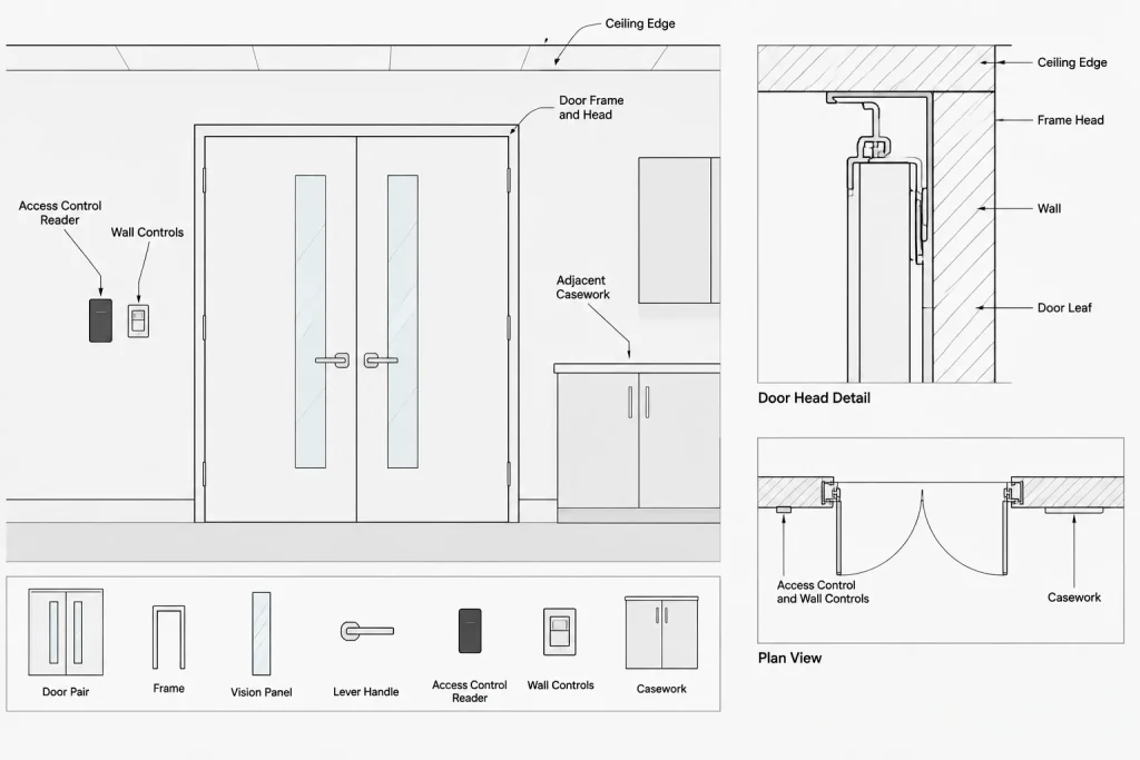
A door may appear to fit in plan while leaving inadequate space for intended hardware or operation. Review nearby corners, cabinets, handrails, glazing, wall protection, switches, controls, fixtures, and other doors. Examine both sides of the opening rather than checking only the swing side.
Review frame and head conditions
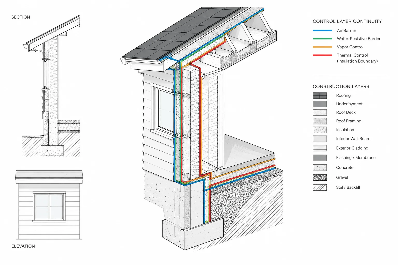
Closers, operators, tracks, sensors, and other devices can interact with the frame head, ceiling, bulkhead, trim, and wall finish. Use interior elevations, enlarged plans, sections, or details when the general floor plan cannot communicate the relationship clearly.
Coordinate pairs and special leaves
Door pairs require careful identification because active and inactive leaves may have different components and functions. Confirm that the plan swing, schedule description, elevations, and hardware notes all describe the same arrangement. Similar checks apply to sliding, folding, revolving, coiling, and other specialty openings, which should not be forced into conventions intended for typical swinging doors.
Manage access-control and electrical interfaces
Electrified hardware introduces information shared among architectural, electrical, security, and sometimes mechanical or fire-protection documents. The architectural drawing should not independently invent wiring, power, monitoring, or sequence requirements. Instead, identify the coordinated opening and provide enough context for the responsible disciplines to connect their work.
A useful coordination matrix can list the door identifier, hardware set, device description, responsible drawing or specification location, power requirement status, control status, and unresolved questions. This matrix may be a working document rather than a construction sheet. Its value is in exposing gaps before issue.
Pay particular attention to inconsistent terminology. A device described one way on the architectural plan and another way on the security plan may represent either a harmless naming difference or a real scope conflict. Resolve the meaning instead of simply making the labels look alike.
Use CAD tools without creating parallel data
Blocks with attributes can help standardize door tags and optional device symbols. Fields such as door identifier, device code, or review status can support checking, but only if the team maintains them. Avoid storing critical information in invisible attributes that are not represented in schedules or review outputs.
Keep hardware coordination layers separate from permanent door geometry. Temporary layers can hold consultant markups, unresolved symbols, or comparison notes. Name them clearly and remove or archive them according to the project workflow before issuing drawings.
When external references are used, avoid copying doors into multiple host files merely to add hardware information. Prefer annotation in the designated documentation file, with a stable reference to the underlying opening. Duplicated geometry tends to drift after plan revisions.
Run a focused quality-control review
Complete the hardware review after major plan changes and again before an issue. A practical check should include:
- Every relevant plan opening has a unique and readable identifier.
- Every identifier appears once in the controlling door inventory.
- Door swings and leaf configurations agree across plans, enlarged views, and schedules.
- Hardware set assignments are present or clearly marked as unresolved.
- Special devices shown in plan are explained by a legend or coordinated document.
- Powered and controlled openings appear in the appropriate consultant information.
- Nearby construction has been checked for operational and mounting conflicts.
- Demolition, existing, and new work conditions are not mixed unintentionally.
- Revision clouds or notes identify changed information without hiding door tags.
- Printed output remains readable in grayscale and at the intended sheet scale.
Finish by comparing the CAD drawing with the current schedule, specification, and consultant markups rather than reviewing each document in isolation. Door hardware coordination succeeds when all parts of the information chain describe the same opening, not merely when each individual sheet looks complete.
Make door coordination changes traceable
Coordination problems often begin when a plan change reaches only part of the documentation set. Moving an opening, reversing a swing, changing a pair configuration, or revising the rooms served by a door may affect the schedule, hardware assignment, details, specifications, and consultant information.
Use a project change log or coordination register to record:
- Door identifier: the stable reference used across drawings and schedules.
- Observed change: what changed in the plan, opening condition, or project requirement.
- Affected documents: the schedules, details, specifications, and consultant drawings that require review.
- Responsible party: the person or discipline expected to resolve or confirm the issue.
- Current status: whether the item remains unresolved, is under review, or has been incorporated.
This record should support the drawings rather than become another independent source of hardware requirements. Once a decision is approved, update the controlling documents and close the corresponding coordination item.
Review by exception instead of rereading everything
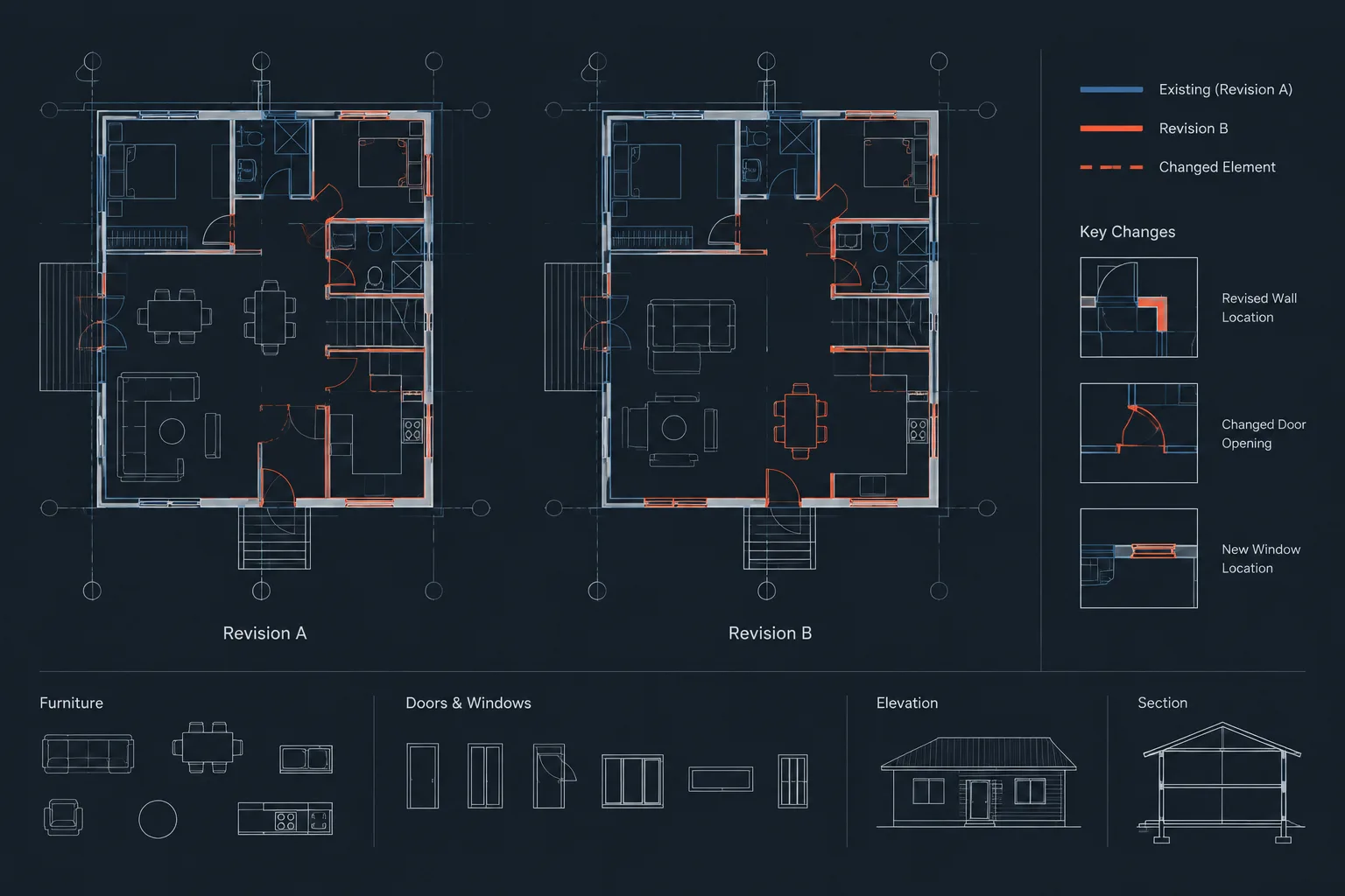
After a drawing revision, focus the next coordination pass on changed openings and on doors whose surrounding conditions were affected. A door may require renewed review even when its tag did not change, particularly if adjacent walls, ceilings, casework, controls, or circulation conditions were revised.
Comparison markups are most useful when they identify meaningful differences rather than every graphical edit. Separate drafting cleanup from changes that could affect operation, hardware assignment, device location, or consultant scope. This makes review comments easier to resolve and reduces the chance that an important opening change will be hidden among unrelated revisions.
Keep deliverables readable to different reviewers
Architects, hardware consultants, contractors, security designers, and electrical consultants may review the same opening for different reasons. Use consistent door identifiers and plain terminology so each reviewer can connect comments to the correct plan location and schedule entry.
A coordination view may contain temporary status graphics or device annotations that do not belong on the final architectural sheet. Before issue, distinguish working information from required contract-document content, then archive or remove temporary markup according to the project workflow.
Door Hardware Coordination FAQ
Should every hardware component be drawn on the floor plan?
No. Floor plans generally need to communicate the opening, leaf arrangement, swing where applicable, and door identifier. Show individual devices when their location affects coordination or when another discipline needs a clear interface. The hardware set and related documents can carry information that would otherwise clutter the plan.
What should control when the plan and door schedule disagree?
The project team should establish an authoritative source for each type of information. Treat a disagreement as a coordination issue rather than assuming either document is correct. Confirm the intended opening, update the controlling source, and reconcile every affected drawing and schedule.
Can doors that look alike use the same hardware set?
Not automatically. Similar door geometry does not confirm identical operation, security, exposure, adjacent conditions, or system interfaces. Review the function and physical context of each opening before assigning a set.
How should unresolved hardware decisions appear in CAD?
Use a clear text status, coordination note, or controlled markup layer. Avoid guessing at a final assignment, and do not rely only on color because the information must remain understandable in printed, exported, and grayscale output.
Why should hardware coordination layers be separate from door geometry?
Separate layers allow reviewers to display temporary notes and device information without altering the underlying architectural opening. They also make it easier to suppress coordination graphics when they are not appropriate for a published plan.
When should door hardware coordination be reviewed again?
Repeat the review whenever relevant plan conditions change and before a drawing issue. Recheck not only edited doors but also openings affected by revisions to nearby construction, room use, ceilings, controls, or consultant systems.